


FPGA中级项目7———TFT显示与驱动
老样子,啥是TFT?
TFT(Thin - Film Transistor)即薄膜晶体管,是一种用于液晶显示器(LCD)等显示设备的技术

TFT 显示屏由大量的像素组成,每个像素包含一个液晶盒以及与之对应的 TFT 开关元件等。当没有电场作用时,液晶分子的排列使得光线能够通过液晶盒,并在经过偏振片等光学元件后,呈现出特定的亮度和颜色。当有电场施加时,液晶分子会在电场作用下发生旋转或扭曲,改变其对光线的偏振方向和透过率。通过控制每个像素点上液晶分子的旋转角度,可以精确控制该像素点的透光量,进而实现不同的灰度和颜色显示。例如,在彩色 TFT 显示屏中,通过在每个像素点上设置红、绿、蓝三种颜色的子像素,并分别控制它们的亮度,就可以组合出各种不同的颜色,最终形成完整的图像。
有着40 Pin排针接线能提供丰富的功能和稳定的数据传输,这种 TFT 显示屏可应用于多种场景,如工业控制设备的人机交互界面、汽车电子的仪表盘显示、智能家居设备的显示屏等。
TFT 显示屏有诸多重要参数
分辨率:指屏幕上像素的数量,通常用水平像素数乘以垂直像素数来表示,如 1920×1080;800×480等。较高的分辨率意味着屏幕能够显示更清晰、更细腻的图像和文字。
尺寸:以屏幕对角线的长度来衡量,单位一般为英寸。常见的尺寸有 3.5 英寸、5 英寸、7 英寸等。
色彩深度:表示每个像素点能够显示的颜色数量,常见的有 18 位(26 万色)和 24 位(1677 万色)。色彩深度越高,显示的颜色越丰富、越逼真。
亮度:单位是尼特(nit),它反映了屏幕的发光强度。高亮度的屏幕在明亮的环境下也能清晰显示内容,一般户外使用的显示屏需要较高的亮度。
对比度:是屏幕上最亮区域与最暗区域的亮度比值。较高的对比度能够使图像的亮部更亮,暗部更暗,从而呈现出更鲜明的色彩和更丰富的细节。
响应时间:指像素点从一种颜色转换到另一种颜色所需的时间,单位为毫秒(ms)。响应时间越短,在显示动态画面时越不容易出现拖影现象,适合用于播放视频和游戏等场景。
真彩色为RGB888(在上一节内容便是),但是为了节约布线与硬件资源,可以进行简化为RGB565,便是取红绿蓝的各高565位,也称为伪真彩色。两者可相互转化
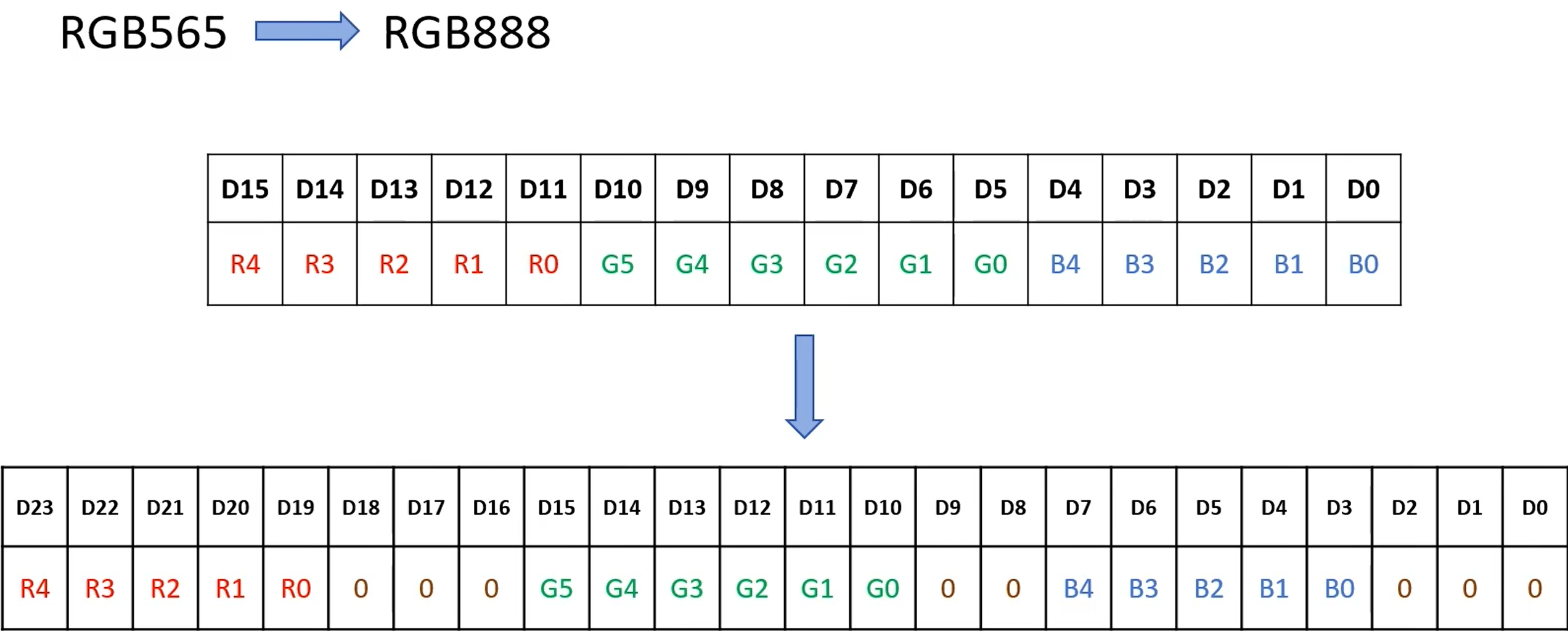
像素点是构成图像的最小单位,每个像素点的颜色由红(R)、绿(G)、蓝(B)三种基本颜色按照不同比例混合而成。RGB888 和 RGB565 决定了每个像素点中这三种颜色的表示方式和精度。
RGB888 比 RGB565 能表示的颜色种类更多。RGB888 格式中,红色、绿色、蓝色三个通道各用 8 位来表示,每个通道都有(2^8 = 256)种不同的取值,那么总共能表示的颜色数量为(256×256×256 = 16777216)种。RGB565 格式中,红色通道用 5 位表示,有(2^5 = 32)种取值;绿色通道用 6 位表示,有(2^6 = 64)种取值;蓝色通道用 5 位表示,有(2^5 = 32)种取值。所以 RGB565 能表示的颜色数量是(32×64×32 = 65536)种。两者可表示的颜色数量相差(16777216 - 65536 = 16711680)种。因此,RGB888 比 RGB565 多了 16711680 种颜色。
非常幸运的是:TFT的显示无需另外的代码。只需要将上一节VGA的内容相应地方根据排线接口修改即可
TFT代码如下
TFT模块代码如下:
//定义输入输出端口
module TFT(
        clk,
        reset_n,
        data_in,//用户输入数据
        TFT_HS,//行同步信号
        TFT_VS,//场同步信号
        hcount,//行扫描位置
        vcount,//场扫描位置
        TFT_DE,//数据输出时间段
        TFT_CLK,
        data_out,
        TFT_BL
    );
        input clk;
        input reset_n;
        input [23:0]data_in;
        output TFT_HS;
        output TFT_VS;
        output [10:0]hcount;//行同步的信号最大值为1056
        output [10:0]vcount;
        output TFT_DE;
        output TFT_CLK;
        output [23:0]data_out;
        output TFT_BL;


// 定义不同的分辨率
//`define resolution_480x272 1 // 时钟为9MHz
//`define resolution_640x480 1 // 时钟为25MHz
`define resolution_800x480 1 // 时钟为33MHz
//`define resolution_800x600 1 // 时钟为40MHz
//`define resolution_1024x600 1 // 时钟为51MHz
//`define resolution_1024x768 1 // 时钟为65MHz
//`define resolution_1280x720 1 // 时钟为74.25MHz
//`define resolution_1920x1080 1 // 时钟为148.5MHz

`ifdef resolution_480x272
    `define h_right_border 0
    `define h_front_porch 2
    `define h_sync_time 41
    `define h_back_porch 2
    `define h_left_border 0
    `define h_data_time 480
    `define h_total_time 525

    `define v_bottom_border 0
    `define v_front_porch 2
    `define v_sync_time 10
    `define v_back_porch 2
    `define v_top_border 0
    `define v_data_time 272
    `define v_total_time 286

`elsif resolution_640x480
    `define h_right_border 0
    `define h_front_porch 16
    `define h_sync_time 96
    `define h_back_porch 48
    `define h_left_border 0
    `define h_data_time 640
    `define h_total_time 800

    `define v_bottom_border 0
    `define v_front_porch 10
    `define v_sync_time 2
    `define v_back_porch 33
    `define v_top_border 0
    `define v_data_time 480
    `define v_total_time 525

`elsif resolution_800x480
    `define h_right_border 0
    `define h_front_porch 40
    `define h_sync_time 128
    `define h_back_porch 88
    `define h_left_border 0
    `define h_data_time 800
    `define h_total_time 1056

    `define v_bottom_border 8
    `define v_front_porch 2
    `define v_sync_time 2
    `define v_back_porch 25
    `define v_top_border 8
    `define v_data_time 480
    `define v_total_time 525

`elsif resolution_800x600
    `define h_right_border 0
    `define h_front_porch 40
    `define h_sync_time 128
    `define h_back_porch 88
    `define h_left_border 0
    `define h_data_time 800
    `define h_total_time 1056

    `define v_bottom_border 0
    `define v_front_porch 1
    `define v_sync_time 4
    `define v_back_porch 23
    `define v_top_border 0
    `define v_data_time 600
    `define v_total_time 628

`elsif resolution_1024x600
    `define h_right_border 0
    `define h_front_porch 24
    `define h_sync_time 136
    `define h_back_porch 160
    `define h_left_border 0
    `define h_data_time 1024
    `define h_total_time 1344

    `define v_bottom_border 0
    `define v_front_porch 1
    `define v_sync_time 3
    `define v_back_porch 28
    `define v_top_border 0
    `define v_data_time 600
    `define v_total_time 632

`elsif resolution_1024x768
    `define h_right_border 0
    `define h_front_porch 24
    `define h_sync_time 136
    `define h_back_porch 160
    `define h_left_border 0
    `define h_data_time 1024
    `define h_total_time 1344

    `define v_bottom_border 0
    `define v_front_porch 3
    `define v_sync_time 6
    `define v_back_porch 29
    `define v_top_border 0
    `define v_data_time 768
    `define v_total_time 806

`elsif resolution_1280x720
    `define h_right_border 0
    `define h_front_porch 110
    `define h_sync_time 40
    `define h_back_porch 220
    `define h_left_border 0
    `define h_data_time 1280
    `define h_total_time 1650

    `define v_bottom_border 0
    `define v_front_porch 5
    `define v_sync_time 5
    `define v_back_porch 36
    `define v_top_border 0
    `define v_data_time 720
    `define v_total_time 750

`elsif resolution_1920x1080
    `define h_right_border 0
    `define h_front_porch 88
    `define h_sync_time 44
    `define h_back_porch 148
    `define h_left_border 0
    `define h_data_time 1920
    `define h_total_time 2200

    `define v_bottom_border 0
    `define v_front_porch 4
    `define v_sync_time 5
    `define v_back_porch 36
    `define v_top_border 0
    `define v_data_time 1080
    `define v_total_time 1125

`endif


 //定义时序中相关信号
        //parameter VGA_HS_end =  11'd127;
        //parameter hdat_begin = 11'd216;//行数据开始输出位置
        //parameter hdat_end = 11'd1016;//行数据停止输出位置
        //parameter hpixel_end = 11'd1055;//行扫描的最大位置处

        //parameter VGA_VS_end =  11'd1;
        //parameter vdat_begin = 11'd35;
        //parameter vdat_end = 11'd515;
        //parameter vpixel_end = 11'd524;

//将上述的parameter定义改为参数定义,便于适配
        parameter  TFT_HS_end = `h_sync_time - 1,
                    hdat_begin = `h_sync_time + `h_back_porch + `h_left_border,
                    hdat_end = `h_sync_time + `h_back_porch + `h_left_border + `h_data_time,
                    hpixel_end = `h_total_time - 1,
                    TFT_VS_end = `v_sync_time - 1,
                    vdat_begin = `v_sync_time + `v_back_porch + `v_top_border,
                    vdat_end = `v_sync_time + `v_back_porch + `v_top_border + `v_data_time,
                    vpixel_end = `v_total_time - 1;


 //定义计数器,开始行扫描信号,场扫描信号计数
        reg [10:0]hcount_r;
        reg [10:0]vcount_r;
always@(posedge clk or negedge reset_n)
if(!reset_n)
        hcount_r <= 11'd0;
else if(hcount_r  == hpixel_end)
        hcount_r <= 11'd0;
else
        hcount_r <= hcount_r + 1'd1;


always@(posedge clk or negedge reset_n)
if(!reset_n)
        vcount_r <= 11'd0;
else if(hcount_r  == hpixel_end)  begin
        if(vcount_r == vpixel_end)
        vcount_r <= 11'd0;
        else
        vcount_r <= vcount_r + 1'd1;
        end
else
        vcount_r <= vcount_r;


//定义相关信号
assign  TFT_HS = (hcount_r > TFT_HS_end) ?1'b1:1'b0;
assign  TFT_VS = (vcount_r > TFT_VS_end) ?1'b1:1'b0;
assign  TFT_DE =((hcount_r >= hdat_begin) &&(hcount_r < hdat_end ) &&(vcount_r >= vdat_begin )&&(vcount_r < vdat_end))?1'b1:1'b0;
assign  hcount = TFT_DE ? (hcount_r - hdat_begin) :10'd0;
assign  vcount = TFT_DE ? (vcount_r - vdat_begin) :10'd0;
assign  data_out = (TFT_DE) ? data_in : 24'h000000;
assign  TFT_CLK = ~clk;
assign  TFT_BL = 1;


endmodule
TFT显示的顶层代码如下:
//定义输入输出端口
module TFT_CTRL(
        clk_50M,
        reset_n,
        TFT_HS,//行同步信号
        TFT_VS,//场同步信号
        TFT_DE,//数据输出时间段
        TFT_CLK,
        data_out,
        TFT_BL
    );
        input clk_50M;
        input reset_n;
        output TFT_HS;
        output TFT_VS;
        output TFT_DE;
        output TFT_CLK;
        output [23:0]data_out;
        output TFT_BL;

//定义相关信号
        reg [23:0]data_in;
        wire locked;
        wire clk;
        wire [11:0]hcount;
        wire [11:0]vcount;


//定义计数器counter0
        reg [31:0]counter0;
always@(posedge clk_50M or negedge reset_n)
if(!reset_n)
        counter0 <= 0;
else if(counter0 == 99_999_999)
        counter0 <= 0;
else
        counter0 <= counter0 + 1'd1;


//定义使能信号
        reg en ;
always@(posedge clk_50M or negedge reset_n)
if(!reset_n)
        en <= 0;
else if(counter0 >= 49_999_999)
        en <= 1;
else
        en <= 0;

//定义颜色代码
localparam   black = 24'h000000,
             blue = 24'h0000FF,
             red = 24'hFF0000,
             purpple = 24'hFF00FF,
             green = 24'h00FF00,
             cyan = 24'h00FFFF,
             yellow = 24'hFFFF00,
             white = 24'hFFFFFF;


//例化时钟IP核 33M
            clk_33 clk_33
   (
    // Clock out ports
    .clk_out1(clk),     // output clk_out1
    // Status and control signals
    .reset(!reset_n), // input reset
    .locked(locked),       // output locked
   // Clock in ports
    .clk_in1(clk_50M));


//例化已经写好的TFT块
         TFT(
                 .clk(clk),
                 .reset_n(reset_n),
                 .data_in(data_in),//用户输入数据
                 .TFT_HS(TFT_HS),//行同步信号
                 .TFT_VS(TFT_VS),//场同步信号
                 .hcount(hcount),//行扫描位置
                 .vcount(vcount),//场扫描位置
                 .TFT_DE(TFT_DE),//数据输出时间段
                 .TFT_CLK(TFT_CLK),
                 .data_out(data_out),
                 .TFT_BL(TFT_BL)
             );


//定义扫描像素块
        wire c0_act = hcount >= 0 && hcount <400;//扫描第0列
        wire c1_act = hcount >= 400 && hcount <800;//扫描第1列
        wire r0_act = vcount >= 0 && vcount < 120;//扫描第0行
        wire r1_act = vcount >= 120 && vcount < 240;//扫描第1行
        wire r2_act = vcount >= 240 && vcount < 360;//扫描第2行
        wire r3_act = vcount >= 360 && vcount < 480;//扫描第3行
        wire r0_c0_act = r0_act & c0_act;//定位第0列,第0行像素块扫描
        wire r0_c1_act = r0_act & c1_act;//定位第0列,第1行像素块扫描
        wire r1_c0_act = r1_act & c0_act;//定位第1列,第0行像素块扫描
        wire r1_c1_act = r1_act & c1_act;//定位第1列,第1行像素块扫描
        wire r2_c0_act = r2_act & c0_act;//定位第2列,第0行像素块扫描
        wire r2_c1_act = r2_act & c1_act;//定位第2列,第1行像素块扫描
        wire r3_c0_act = r3_act & c0_act;//定位第3列,第0行像素块扫描
        wire r3_c1_act = r3_act & c1_act;//定位第3列,第1行像素块扫描


//定义像素块显示颜色
always@(posedge clk)
if(en == 1) begin
case({r3_c1_act, r3_c0_act,r2_c1_act,r2_c0_act,r1_c1_act,r1_c0_act,r0_c1_act,r0_c0_act})
        8'b0000_0001 :  data_in <= black;
        8'b0000_0010 :  data_in <= blue;
        8'b0000_0100 :  data_in <= red;
        8'b0000_1000 :  data_in <= purpple;
        8'b0001_0000 :  data_in <= green;
        8'b0010_0000 :  data_in <= cyan;
        8'b0100_0000 :  data_in <= yellow;
        8'b1000_0000 :  data_in <= white;
        endcase
        end
else
        data_in <= 24'h0000FF;


endmodule
需要指出的是,进行TFT显示和VGA显示的原理一致,回扫时间,行同步脉冲信号,行同步结束信号,行扫描最大位置等按照芯片手册规定的时钟周期来定义
视频效果呈现
TFT显示


 被折叠的 条评论
为什么被折叠?
被折叠的 条评论
为什么被折叠?
 到【灌水乐园】发言


