


实验要求:
1.内网IP地址172.16.0.0/16合理分配
2. SW1/2之间互为备份
3.. VRRP/STP/MLAN/TRUNK均使用。,
4、所有PC通过DHCP获取ip地址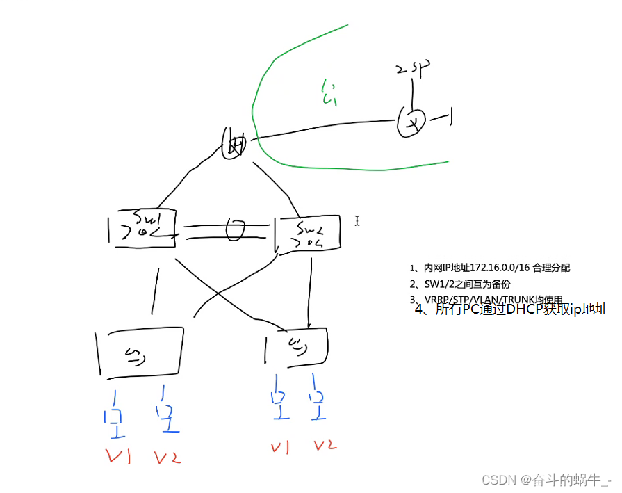
实验步骤及实验结果:
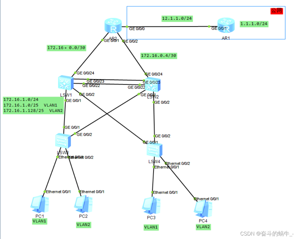
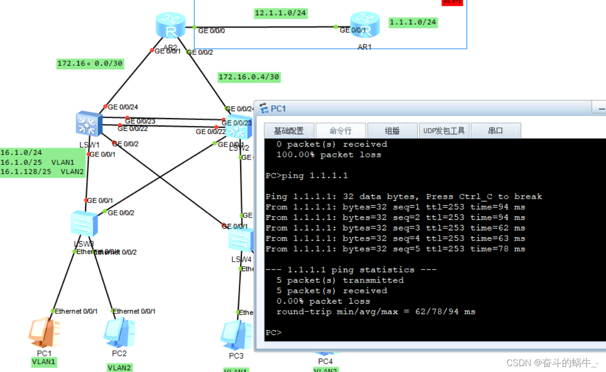
1、IP地址规划拓扑设计:
2、配置交换机
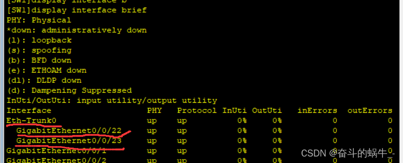
1)创建Eth-Trunk 0并绑定g0/0/22和g0/0/23接口
SW1:
[SW1-Eth-Trunk0]interface Eth-Trunk 0
[SW1-Eth-Trunk0]q
[SW1]interface g0/0/22
[SW1-GigabitEthernet0/0/22]eth-trunk 0
[SW1-GigabitEthernet0/0/22]q
[SW1]interface g0/0/23
[SW1-GigabitEthernet0/0/23]eth-trunk 0SW2:
[SW2]interface Eth-Trunk 0
[SW2-Eth-Trunk0]q
[SW2]interface g0/0/22
[SW2-GigabitEthernet0/0/22]eth-trunk 0
[SW2-GigabitEthernet0/0/22]q
[SW2]int g0/0/23
[SW2-GigabitEthernet0/0/23]eth-trunk 0
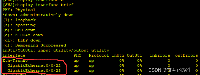
查看SW1和SW2的接口信息
2)创建VLAN和划分VLAN
SW1:
[SW1]vlan 2
[SW1-vlan2]q
[SW1]port-group group-member GigabitEthernet 0/0/1 to GigabitEthernet 0/0/2 Eth-
Trunk 0
[SW1-port-group]port link-type trunk
[SW1-port-group]port trunk allow-pass vlan 2SW2:
[SW2]vlan 2
[SW2-vlan2]q
[SW2]port-group group-member GigabitEthernet 0/0/1 to GigabitEthernet 0/0/2 Eth-
Trunk 0
[SW2-port-group]port link-type trunk
[SW2-port-group]port trunk allow-pass vlan 2SW3:(由于e0/0/1默认在VLAN1不用划分,只需要划分e0/0/2和配置vlan模式)
[SW3-vlan2]vlan 2
[SW3-vlan2]q
[SW3]int e0/0/2
[SW3-Ethernet0/0/2]port link-type access
[SW3-Ethernet0/0/2]port default vlan 2
[SW3-Ethernet0/0/2]q
[SW3]port-group group-member g0/0/1 to g0/0/2
[SW3-port-group]port link-type trunk
[SW3-port-group]port trunk allow-pass vlan 2SW4:(由于e0/0/1默认在VLAN1不用划分,只需要划分e0/0/2和配置vlan模式)
[SW4]vlan 2
[SW4-vlan2]q
[SW4]int e0/0/2
[SW4-Ethernet0/0/2]port link-type access
[SW4-Ethernet0/0/2]port default vlan 2
[SW4-Ethernet0/0/2]q
[SW4]port-group group-member GigabitEthernet 0/0/1 to GigabitEthernet 0/0/2
[SW4-port-group]port link-type trunk
[SW4-port-group]port trunk allow-pass vlan 2
3)创建STP组
SW1:
[SW1]stp region-configuration
[SW1-mst-region]region-name a
[SW1-mst-region]instance 1 vlan 1
[SW1-mst-region]instance 2 vlan 2
[SW1-mst-region]active region-configurationSW2:
[SW2]stp region-configuration
[SW2-mst-region]region-name a
[SW2-mst-region]instance 1 vlan 1
[SW2-mst-region]instance 2 vlan 2
[SW2-mst-region]active region-configurationSW3:
[SW3]stp region-configuration
[SW3-mst-region]region-name a
[SW3-mst-region]instance 1 vlan 1
[SW3-mst-region]instance 2 vlan 2
[SW3-mst-region]active region-configurationSW4:
[SW4]stp region-configuration
[SW4-mst-region]region-name a
[SW4-mst-region]instance 1 vlan 1
[SW4-mst-region]instance 2 vlan 2
[SW4-mst-region]active region-configuration在SW1上指定组1为主根组2为备份根;在SW2上指定组2为主根组1为备份根:
[SW1]stp instance 1 root primary
[SW1]stp instance 2 root secondary[SW2]stp instance 2 root primary
[SW2]stp instance 1 root secondary为了使SW3和SW4一直作为接入层,故在SW1上指定组0为主根,SW2上组0为备份根:
[SW1]stp instance 0 root primary
[SW2]stp instance 0 root secondary
在SW3和SW4上的用户接口做STP的边缘接口,为了将SW3和SW4的用户接口不再发BPDU骚扰用户接口的用户
[SW3]port-group group-member Ethernet 0/0/1 to Ethernet 0/0/22
[SW3-port-group]stp edged-port enable
[SW4]port-group group-member Ethernet 0/0/1 to Ethernet 0/0/22
[SW4-port-group]stp edged-port enable拟定e0/0/3接口为连接wifi的接口,若出现环路优先阻塞有线接口,故更改STP优先级
[SW3]int e0/0/3
[SW3-Ethernet0/0/3]stp instance 0 port priority 16
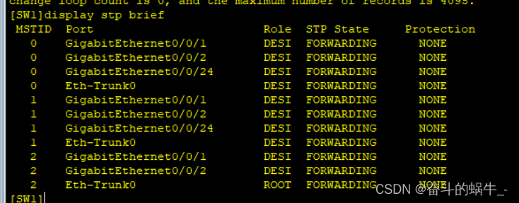
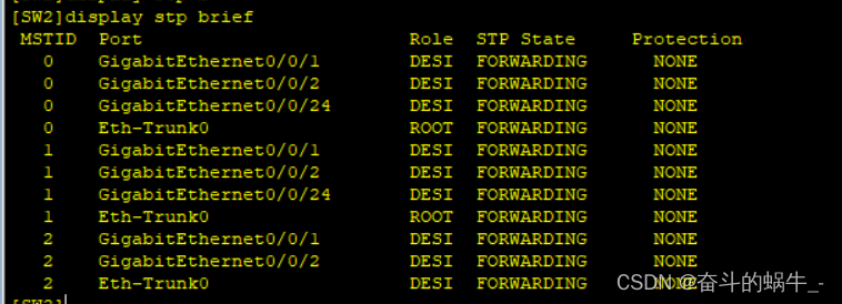
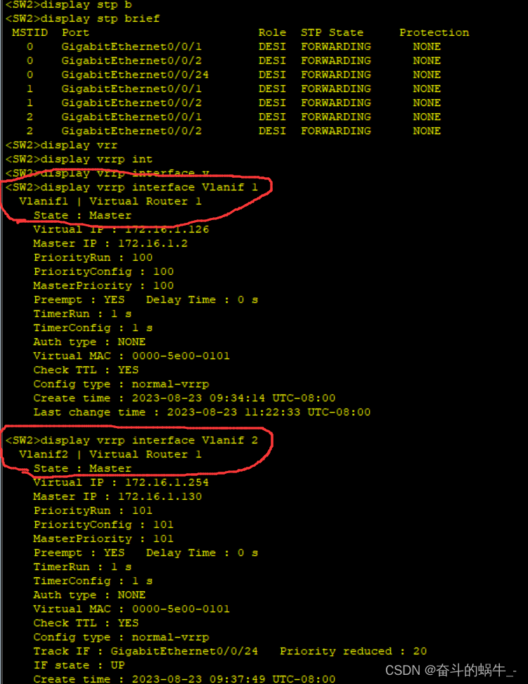
查看STP:
4)配置SVI
[SW1]interface Vlanif 1
[SW1-Vlanif1]ip address 172.16.1.1 25
[SW1-Vlanif1]q
[SW1]interface Vlanif 2
[SW1-Vlanif2]ip address 172.16.1.129 25[SW2]interface Vlanif 1
[SW2-Vlanif1]ip address 172.16.1.2 25
[SW2-Vlanif1]q
[SW2]interface v
[SW2]interface Vlanif 2
[SW2-Vlanif2]ip address 172.16.1.130 25
5)配置VRRP网关冗余备份
SW1上vlan1为主:
[SW1]interface Vlanif 1
[SW1-Vlanif1]vrrp vrid 1 virtual-ip 172.16.1.126
[SW1-Vlanif1]vrrp vrid 1 priority 101
[SW1-Vlanif1]vrrp vrid 1 track interface GigabitEthernet 0/0/24 reduced 20 #上行链路追踪[SW2]interface Vlanif 1
[SW2-Vlanif1]vrrp vrid 1 virtual-ip 172.16.1.126SW2上vlan2为主:
[SW2]interface Vlanif 2
[SW2-Vlanif2]vrrp vrid 1 virtual-ip 172.16.1.254
[SW2-Vlanif2]vrrp vrid 1 priority 101
[SW2-Vlanif2]vrrp vrid 1 track interface GigabitEthernet 0/0/24 reduced 20 #上行链路追踪[SW1]interface Vlanif 2
[SW1-Vlanif2]vrrp vrid 1 virtual-ip 172.16.1.254
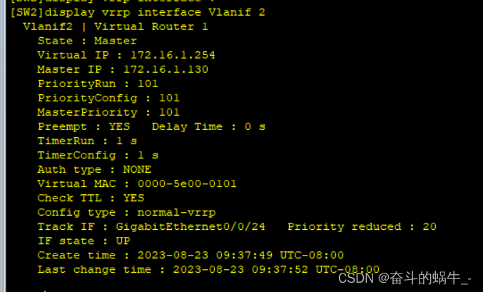
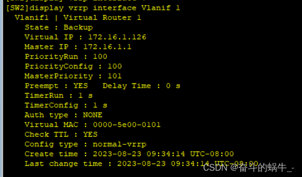
查看VRRP:
6)配置DHCP获取IP地址
SW1:
[SW1]dhcp enable
[SW1]ip pool v1
[SW1-ip-pool-v1]network 172.16.1.0 mask 25
[SW1-ip-pool-v1]gateway-list 172.16.1.126
[SW1-ip-pool-v1]dns-list 114.114.114.114 8.8.8.8
[SW1-ip-pool-v1]q
[SW1]ip pool v2
[SW1-ip-pool-v2]network 172.16.1.128 mask 25
[SW1-ip-pool-v2]gateway-list 172.16.1.254
[SW1-ip-pool-v2]dns-list 114.114.114.114 8.8.8.8
[SW1-ip-pool-v2]q
[SW1]interface Vlanif 1
[SW1-Vlanif1]dhcp select gl
[SW1-Vlanif1]dhcp select global
[SW1-Vlanif1]q
[SW1]interface Vlanif 2
[SW1-Vlanif2]dhcp select globalSW2:
[SW2]dhcp enable
[SW2]ip pool v1
[SW2-ip-pool-v1] gateway-list 172.16.1.126
[SW2-ip-pool-v1] network 172.16.1.0 mask 255.255.255.128
[SW2-ip-pool-v1] dns-list 114.114.114.114 8.8.8.8
[SW2-ip-pool-v1]ip pool v2
[SW2-ip-pool-v2] gateway-list 172.16.1.254
[SW2-ip-pool-v2] network 172.16.1.128 mask 255.255.255.128
[SW2-ip-pool-v2] dns-list 114.114.114.114 8.8.8.8
[SW2-ip-pool-v2]q
[SW2]interface Vlanif 1
[SW2-Vlanif1]dhcp select global
[SW2-Vlanif1]q
[SW2]interface Vlanif 2
[SW2-Vlanif2]dhcp select global
3、配置路由器
1)配置路由器IP地址
[Huawei]sysname ISP
[ISP]int g0/0/1
[ISP-GigabitEthernet0/0/1]ip address 12.1.1.2 24
[ISP-GigabitEthernet0/0/0]int lo0
[ISP-LoopBack0]ip address 1.1.1.1 24[Huawei]sysname r2
[r2]int g0/0/0
[r2-GigabitEthernet0/0/0]ip address 12.1.1.1 24
[r2]int g0/0/1
[r2-GigabitEthernet0/0/1]ip address 172.16.0.1 30
[r2-GigabitEthernet0/0/1]int g0/0/2
[r2-GigabitEthernet0/0/2]ip address 172.16.0.5 30
2)配置三层交换机的上行接口IP地址
SW1:
#由于华为模拟器三层交换机不能直接配置IP地址,故需要创建一个vlan组配置IP地址
[SW1]vlan 99
[SW1-vlan99]q
[SW1]int g0/0/24
[SW1-GigabitEthernet0/0/24]port link-type access
[SW1-GigabitEthernet0/0/24]port default vlan 99[SW1]interface Vlanif 99
[SW1-Vlanif99]ip address 172.16.0.2 30SW2:
#由于华为模拟器三层交换机不能直接配置IP地址,故需要创建一个vlan组配置IP地址
[SW2]vlan 99
[SW2-vlan99]q
[SW2]int g0/0/24
[SW2-GigabitEthernet0/0/24]port link-type access
[SW2-GigabitEthernet0/0/24port default vlan 99
[SW2-GigabitEthernet0/0/24]q
[SW2]interface Vlanif 99
[SW2-Vlanif99]ip address 172.16.0.6 30
3)写路由配置OSPF
r2:
[r2]ospf 1 router-id 2.2.2.2
[r2-ospf-1]area 0
[r2-ospf-1-area-0.0.0.0]network 172.16.0.1 0.0.0.0
[r2-ospf-1-area-0.0.0.0]network 172.16.0.5 0.0.0.0SW1:
[SW1]ospf 1 router-id 3.3.3.3
[SW1-ospf-1]area 0
[SW1-ospf-1-area-0.0.0.0]network 172.16.0.2 0.0.0.0
[SW1-ospf-1-area-0.0.0.0]q
[SW1-ospf-1]area 1
[SW1-ospf-1-area-0.0.0.1]network 172.16.1.1 0.0.0.0
[SW1-ospf-1-area-0.0.0.1]network 172.16.1.129 0.0.0.0SW2:
[SW2]ospf 1 router-id 4.4.4.4
[SW2-ospf-1]area 0
[SW2-ospf-1-area-0.0.0.0]network 172.16.0.6 0.0.0.0
[SW2-ospf-1-area-0.0.0.0]q
[SW2-ospf-1]area 1
[SW2-ospf-1-area-0.0.0.1]network 172.16.1.2 0.0.0.0
[SW2-ospf-1-area-0.0.0.1]network 172.16.1.130 0.0.0.0写缺省重发布到OSPF中:
[r2]ip route-static 0.0.0.0 0.0.0.0 12.1.1.2 #配置缺省指向公网
[r2]ospf 1
[r2-ospf-1]def
[r2-ospf-1]default-route-advertise汇总;做空接口防环:
[SW1]ospf 1
[SW1-ospf-1]area 1
[SW1-ospf-1-area-0.0.0.1]abr-summary 172.16.1.0 255.255.255.0[SW1]ip route-static 172.16.1.0 24 NULL 0 #做空接口
[SW2]ospf 1
[SW2-ospf-1]area 1
[SW2-ospf-1-area-0.0.0.1]
[SW2-ospf-1-area-0.0.0.1]abr-summary 172.16.1.0 255.255.255.0[SW2]ip route-static 172.16.1.0 24 NULL 0 #做空接口
查看R2路由表:
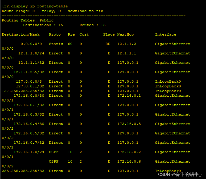
4)做NAT
[r2]acl 2000
[r2-acl-basic-2000]rule permit source 172.16.0.0 0.0.255.255
[r2-acl-basic-2000]q
[r2]interface g0/0/0
[r2-GigabitEthernet0/0/0]nat outbound 2000
5)沉默接口
由于在实际工程中需要管理的接口很多,需要收发很多hello包,故只需要开启一些接口其他接口沉默即可:
SW1:
[SW1]ospf 1
[SW1-ospf-1]silent-interface all #先沉默所有接口
[SW1-ospf-1]undo silent-interface GigabitEthernet 0/0/24 #关闭g0/0/24沉默接口
[SW1-ospf-1]undo silent-interface Vlanif 99 #关闭Vlanif 99沉默接口[SW1-ospf-1]undo silent-interface Eth-Trunk 0 #关闭Eth-Trunk 0 沉默接口
[SW1-ospf-1]undo silent-interface Vlanif 1 #关闭Vlanif 1沉默接口SW2:
[SW2]ospf 1
[SW2-ospf-1]silent-interface all
[SW2-ospf-1]undo silent-interface GigabitEthernet 0/0/24
[SW2-ospf-1]undo silent-interface Vlanif 99
[SW2-ospf-1]undo silent-interface Eth-Trunk 0
[SW2-ospf-1]undo silent-interface Vlanif 1
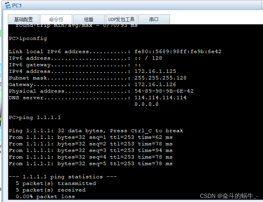
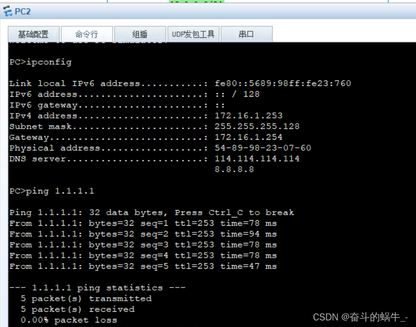
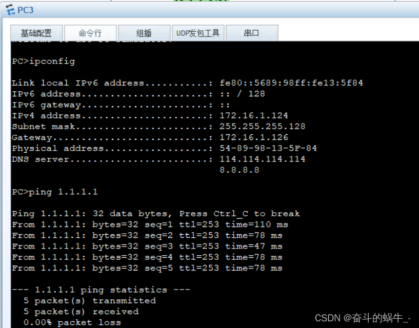
测试用户端访问公网:
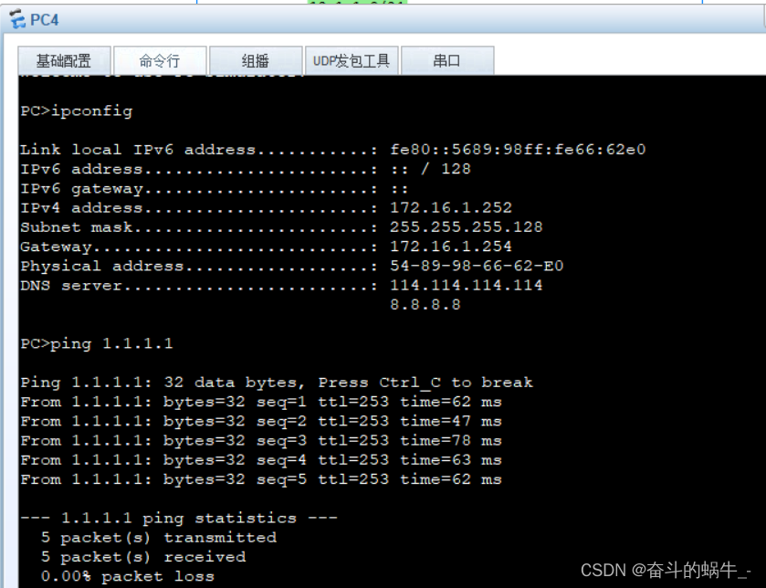
4、在实验完成后测试根root网关备份:
关闭SW1后SW2抢走了根root和网关:
关闭SW1访问1.1.1.1:


 901
901


 被折叠的 条评论
为什么被折叠?
被折叠的 条评论
为什么被折叠?
 到【灌水乐园】发言


