


一、引言
开局一张图,内容全靠编——来吧,展示。。。
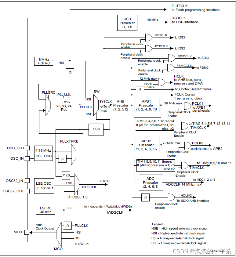
先来说明,这张图是取自于stm32F1系列的使用手册,以下内容也是针对F1系列的小容量(flash在16-32k)、中容量(64-128K)和大容量(256-512K)的系列控制器,与互联型的或者其它系列的有差别但是并不大。搞懂这张图,其它也就手到擒来了。
二、什么是时钟
时钟是由电路产生的具有周期性的脉冲信号,相当于单片机的心脏,给单片机提统一个统一的信号。stm32内提供多个不同的时钟源,每种时钟源的频率也不相同,适用于多种不同的应用场景。想要使用stm32的外设,必要要开启相应的时钟,为了降低功耗这些时钟默认都是关闭的。所以,我们想要在stm32进行相应功能的开发,必须先了解时钟树,根据自己开发需要结合时钟树去配置相应的时钟。
三、时钟树剖析
3.1 四种时钟源
stm32上有4种独立时钟源,分别是:HSI、HSE、LSI、LSE。我看网上也有人说是5个时钟源,还包含PLL。我理解的这种说法不是很对,通过下面学习后你会发现PLL并不是自己产生的时钟源,而是通过其他三种时钟源倍频得到的时钟。
3.1.1 HSE(High-speed external clock signal)
a)HSE可以有两种两种来源,分别是外部晶振和用户外部时钟输入。
①外用户外部输入时钟频率最高可达25Mhz;
②外部晶振频率范围4-16Mhz;
b)HSE的作用主要有以下三种:
①经过不分频或者2分频,作为PLL的输入来源;
②直接作为系统时钟来源;
③经过128分频作为RTC时钟来源;
c)HSE的相关寄存器
Clock control register (RCC_CR)——时钟控制寄存器
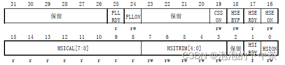
Bit 18 HSEBYP: External high-speed clock bypass
Set and cleared by software to bypass the oscillator with an external clock. The external
clock must be enabled with the HSEON bit set, to be used by the device. The HSEBYP bit
can be written only if the HSE oscillator is disabled.
0: external 4-16 MHz oscillator not bypassed
1: external 4-16 MHz oscillator bypassed with external clock(使用外部输入时钟)
Bit 17 HSERDY: External high-speed clock ready flag
Set by hardware to indicate that the HSE oscillator is stable. This bit needs 6 cycles of the
HSE oscillator clock to fall down after HSEON reset.
0: HSE oscillator not ready
1: HSE oscillator ready
Bit 16 HSEON: HSE clock enable
Set and cleared by software.
Cleared by hardware to stop the HSE oscillator when entering Stop or Standby mode. This
bit cannot be reset if the HSE oscillator is used directly or indirectly as the system clock.
0: HSE oscillator OFF
1: HSE oscillator ON
d)HSE初始化(hal库)
  /*------------------------------- HSE Configuration ------------------------*/
  if (((RCC_OscInitStruct->OscillatorType) & RCC_OSCILLATORTYPE_HSE) == RCC_OSCILLATORTYPE_HSE)
  {
    /* Check the parameters */
    assert_param(IS_RCC_HSE(RCC_OscInitStruct->HSEState));

    //读RCC_CFGR寄存器SWS[1:0]位判断的系统时钟来源是否为HSE,或者如果系统时钟来源为PLL,则需要再读取CFGR寄存器的PLLSRC位判断PLL的输入是否来源于HSE
    /* When the HSE is used as system clock or clock source for PLL in these cases it is not allowed to be disabled */
    if ((__HAL_RCC_GET_SYSCLK_SOURCE() == RCC_SYSCLKSOURCE_STATUS_HSE)
        || ((__HAL_RCC_GET_SYSCLK_SOURCE() == RCC_SYSCLKSOURCE_STATUS_PLLCLK) && (__HAL_RCC_GET_PLL_OSCSOURCE() == RCC_PLLSOURCE_HSE)))
    {
      if ((__HAL_RCC_GET_FLAG(RCC_FLAG_HSERDY) != RESET) && (RCC_OscInitStruct->HSEState == RCC_HSE_OFF))
      {
        return HAL_ERROR;
      }
    }
    else
    {
      //设置RCC_CR寄存器的HSEON位为1
      /* Set the new HSE configuration ---------------------------------------*/
      __HAL_RCC_HSE_CONFIG(RCC_OscInitStruct->HSEState);


      /* Check the HSE State */
      if (RCC_OscInitStruct->HSEState != RCC_HSE_OFF)
      {
        /* Get Start Tick */
        tickstart = HAL_GetTick();

        //判断CR寄存器HSERDY是否由硬件置1
        /* Wait till HSE is ready */
        while (__HAL_RCC_GET_FLAG(RCC_FLAG_HSERDY) == RESET)
        {
          if ((HAL_GetTick() - tickstart) > HSE_TIMEOUT_VALUE)
          {
            return HAL_TIMEOUT;
          }
        }
      }
      else
      {
        /* Get Start Tick */
        tickstart = HAL_GetTick();

        /* Wait till HSE is disabled */
        while (__HAL_RCC_GET_FLAG(RCC_FLAG_HSERDY) != RESET)
        {
          if ((HAL_GetTick() - tickstart) > HSE_TIMEOUT_VALUE)
          {
            return HAL_TIMEOUT;
          }
        }
      }
    }
  }
3.1.2 HSI(High-speed internal clock signal)
HSI时钟信号由内部8MHz的RC振荡器产生,RC振荡器能够在不需要任何外部器件的条件下提供系统时钟。它的启动时间比HSE晶体振荡器短,但是时钟频率精度比较差。
a) HSI的作用
①HSI可直接作为系统时钟;
②在经过2分频后作为PLL输入;
③作为FLASH编程接口的时钟;

b)HSI相关的寄存器
Clock control register (RCC_CR)——时钟控制寄存器
Bits 15:8 HSICAL[7:0]: Internal high-speed clock calibration
These bits are initialized automatically at startup.
Bits 7:3 HSITRIM[4:0]: Internal high-speed clock trimming
These bits provide an additional user-programmable trimming value that is added to the
HSICAL[7:0] bits. It can be programmed to adjust to variations in voltage and temperature
that influence the frequency of the internal HSI RC.
The default value is 16, which, when added to the HSICAL value, should trim the HSI to 8
MHz ± 1%.
Bit 1 HSIRDY: Internal high-speed clock ready flag
Set by hardware to indicate that internal 8 MHz RC oscillator is stable. After the HSION bit is
cleared, HSIRDY goes low after 6 internal 8 MHz RC oscillator clock cycles.
0: internal 8 MHz RC oscillator not ready
1: internal 8 MHz RC oscillator ready
Bit 0 HSION: Internal high-speed clock enable
Set and cleared by software.
Set by hardware to force the internal 8 MHz RC oscillator ON when leaving Stop or Standby
mode or in case of failure of the external 4-16 MHz oscillator used directly or indirectly as
system clock. This bit cannot be reset if the internal 8 MHz RC is used directly or indirectly
as system clock or is selected to become the system clock.
0: internal 8 MHz RC oscillator OFF
1: internal 8 MHz RC oscillator ON
c)HSI初始化 (hal库)
  /*----------------------------- HSI Configuration --------------------------*/
  if (((RCC_OscInitStruct->OscillatorType) & RCC_OSCILLATORTYPE_HSI) == RCC_OSCILLATORTYPE_HSI)
  {
    /* Check the parameters */
    assert_param(IS_RCC_HSI(RCC_OscInitStruct->HSIState));
    assert_param(IS_RCC_CALIBRATION_VALUE(RCC_OscInitStruct->HSICalibrationValue));

    //读RCC_CFGR寄存器SWS[1:0]位判断的系统时钟来源是否为HSI,或者如果系统时钟来源为PLL,则需要再读取RCC_CFGR寄存器的PLLSRC位判断PLL的输入是否来源于HSI经2分频后的时钟
    /* Check if HSI is used as system clock or as PLL source when PLL is selected as system clock */
    if ((__HAL_RCC_GET_SYSCLK_SOURCE() == RCC_SYSCLKSOURCE_STATUS_HSI)
        || ((__HAL_RCC_GET_SYSCLK_SOURCE() == RCC_SYSCLKSOURCE_STATUS_PLLCLK) && (__HAL_RCC_GET_PLL_OSCSOURCE() == RCC_PLLSOURCE_HSI_DIV2)))
    {
      /* When HSI is used as system clock it will not disabled */
      if ((__HAL_RCC_GET_FLAG(RCC_FLAG_HSIRDY) != RESET) && (RCC_OscInitStruct->HSIState != RCC_HSI_ON))
      {
        return HAL_ERROR;
      }
      /* Otherwise, just the calibration is allowed */
      else
      {

        //HSI时钟调整,设置RCC_CR寄存器的HSITRIM[7:3]位,一般设置默认值RCC_HSICALIBRATION_DEFAULT(16)即可
        /* Adjusts the Internal High Speed oscillator (HSI) calibration value.*/
        __HAL_RCC_HSI_CALIBRATIONVALUE_ADJUST(RCC_OscInitStruct->HSICalibrationValue);
      }
    }
    else
    {
      /* Check the HSI State */
      if (RCC_OscInitStruct->HSIState != RCC_HSI_OFF)
      {
        //设置RCC_CR寄存器HSION位为1
        /* Enable the Internal High Speed oscillator (HSI). */
        __HAL_RCC_HSI_ENABLE();

        /* Get Start Tick */
        tickstart = HAL_GetTick();


        //判断CR寄存器HSIRDY是否由硬件置1
        /* Wait till HSI is ready */
        while (__HAL_RCC_GET_FLAG(RCC_FLAG_HSIRDY) == RESET)
        {
          if ((HAL_GetTick() - tickstart) > HSI_TIMEOUT_VALUE)
          {
            return HAL_TIMEOUT;
          }
        }

        /* Adjusts the Internal High Speed oscillator (HSI) calibration value.*/
        __HAL_RCC_HSI_CALIBRATIONVALUE_ADJUST(RCC_OscInitStruct->HSICalibrationValue);
      }
      else
      {
        /* Disable the Internal High Speed oscillator (HSI). */
        __HAL_RCC_HSI_DISABLE();

        /* Get Start Tick */
        tickstart = HAL_GetTick();

        /* Wait till HSI is disabled */
        while (__HAL_RCC_GET_FLAG(RCC_FLAG_HSIRDY) != RESET)
        {
          if ((HAL_GetTick() - tickstart) > HSI_TIMEOUT_VALUE)
          {
            return HAL_TIMEOUT;
          }
        }
      }
    }
  }
3.1.3 LSE(Low -speed external clock signal)
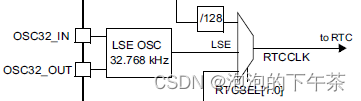
LSE晶体是一个32.768kHz的低速外部晶体或陶瓷谐振器。它为RTC提供一个低功耗且精确的时钟源。
a)LSE相关寄存器
Backup domain control register (RCC_BDCR)—— 备份域控制寄存器
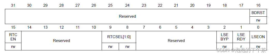
Bit 1 LSERDY: External low-speed oscillator ready
Set and cleared by hardware to indicate when the external 32 kHz oscillator is stable. After
the LSEON bit is cleared, LSERDY goes low after 6 external low-speed oscillator clock
cycles.
0: External 32 kHz oscillator not ready
1: External 32 kHz oscillator ready
Bit 0 LSEON: External low-speed oscillator enable
Set and cleared by software.
0: External 32 kHz oscillator OFF
1: External 32 kHz oscillator ON
b)LSE初始化(hal库)
  /*------------------------------ LSE Configuration -------------------------*/
  if (((RCC_OscInitStruct->OscillatorType) & RCC_OSCILLATORTYPE_LSE) == RCC_OSCILLATORTYPE_LSE)
  {
    FlagStatus       pwrclkchanged = RESET;

    /* Check the parameters */
    assert_param(IS_RCC_LSE(RCC_OscInitStruct->LSEState));

    /* Update LSE configuration in Backup Domain control register    */
    /* Requires to enable write access to Backup Domain of necessary */
    //如果RCC_APB1ENR寄存器的PWREN位为0则将其置1
    if (__HAL_RCC_PWR_IS_CLK_DISABLED())
    {
      __HAL_RCC_PWR_CLK_ENABLE();
      pwrclkchanged = SET;
    }

    //如果电源控制模块的PWR_CR寄存器的DBP为0,则将其置1,允许写入RTC和备份寄存器
    if (HAL_IS_BIT_CLR(PWR->CR, PWR_CR_DBP))
    {
      /* Enable write access to Backup domain */
      SET_BIT(PWR->CR, PWR_CR_DBP);

      /* Wait for Backup domain Write protection disable */
      tickstart = HAL_GetTick();

      while (HAL_IS_BIT_CLR(PWR->CR, PWR_CR_DBP))
      {
        if ((HAL_GetTick() - tickstart) > RCC_DBP_TIMEOUT_VALUE)
        {
          return HAL_TIMEOUT;
        }
      }
    }

    //设置RCC_BDCR寄存器的LSEON位,并判断是否成功或超时
    /* Set the new LSE configuration -----------------------------------------*/
    __HAL_RCC_LSE_CONFIG(RCC_OscInitStruct->LSEState);
    /* Check the LSE State */
    if (RCC_OscInitStruct->LSEState != RCC_LSE_OFF)
    {
      /* Get Start Tick */
      tickstart = HAL_GetTick();

      /* Wait till LSE is ready */
      while (__HAL_RCC_GET_FLAG(RCC_FLAG_LSERDY) == RESET)
      {
        if ((HAL_GetTick() - tickstart) > RCC_LSE_TIMEOUT_VALUE)
        {
          return HAL_TIMEOUT;
        }
      }
    }
    else
    {
      /* Get Start Tick */
      tickstart = HAL_GetTick();

      /* Wait till LSE is disabled */
      while (__HAL_RCC_GET_FLAG(RCC_FLAG_LSERDY) != RESET)
      {
        if ((HAL_GetTick() - tickstart) > RCC_LSE_TIMEOUT_VALUE)
        {
          return HAL_TIMEOUT;
        }
      }
    }
    //将RCC_APB1ENR寄存器的PWREN位置0
    /* Require to disable power clock if necessary */
    if (pwrclkchanged == SET)
    {
      __HAL_RCC_PWR_CLK_DISABLE();
    }
  }
3.1.4 LSI(Low-speed internal clock signal)
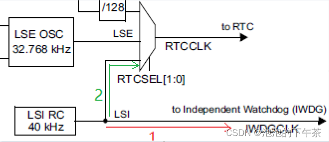
LSI RC担当一个低功耗时钟源的角色,它可以在停机和待机模式下保持运行。LSI时钟频率大约40kHz(在30kHz和60kHz之间)。
a)LSI的作用
①为独立看门狗提供时钟;
②作为RTC时钟输入;
b)LSI相关寄存器
Control/status register (RCC_CSR)——控制/状态寄存器
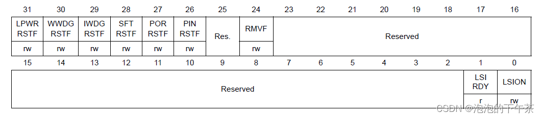
Bit 1 LSIRDY: Internal low-speed oscillator ready
Set and cleared by hardware to indicate when the internal RC 40 kHz oscillator is stable.
After the LSION bit is cleared, LSIRDY goes low after 3 internal RC 40 kHz oscillator clock
cycles.
0: Internal RC 40 kHz oscillator not ready
1: Internal RC 40 kHz oscillator ready
Bit 0 LSION: Internal low-speed oscillator enable
Set and cleared by software.
0: Internal RC 40 kHz oscillator OFF
1: Internal RC 40 kHz oscillator ON
c)LSI初始化(hal库)
  /*------------------------------ LSI Configuration -------------------------*/
  if (((RCC_OscInitStruct->OscillatorType) & RCC_OSCILLATORTYPE_LSI) == RCC_OSCILLATORTYPE_LSI)
  {
    /* Check the parameters */
    assert_param(IS_RCC_LSI(RCC_OscInitStruct->LSIState));

    /* Check the LSI State */
    if (RCC_OscInitStruct->LSIState != RCC_LSI_OFF)
    {

      //将RCC_CSR寄存器的LSION位置1,使能LSI
      /* Enable the Internal Low Speed oscillator (LSI). */
      __HAL_RCC_LSI_ENABLE();

      /* Get Start Tick */
      tickstart = HAL_GetTick();

      /* Wait till LSI is ready */
      //判断CSR寄存器LSIRDY是否由硬件置1
      while (__HAL_RCC_GET_FLAG(RCC_FLAG_LSIRDY) == RESET)
      {
        if ((HAL_GetTick() - tickstart) > LSI_TIMEOUT_VALUE)
        {
          return HAL_TIMEOUT;
        }
      }
      /*  To have a fully stabilized clock in the specified range, a software delay of 1ms
          should be added.*/
      RCC_Delay(1);
    }
    else
    {
      //将CSR寄存器的LSION位置0,失能LSI
      /* Disable the Internal Low Speed oscillator (LSI). */
      __HAL_RCC_LSI_DISABLE();

      /* Get Start Tick */
      tickstart = HAL_GetTick();

      /* Wait till LSI is disabled */
      while (__HAL_RCC_GET_FLAG(RCC_FLAG_LSIRDY) != RESET)
      {
        if ((HAL_GetTick() - tickstart) > LSI_TIMEOUT_VALUE)
        {
          return HAL_TIMEOUT;
        }
      }
    }
  }
3.2 PLL(Phase-Locked Loop)
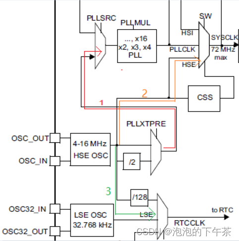
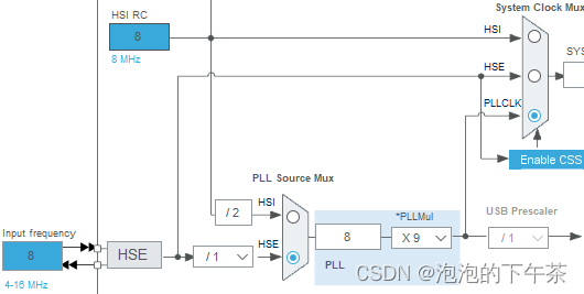
PLL锁相环用于将较低频率的外部或内部时钟源(例如HSI或HSE)经过倍频变成PLLCLK作为系统时钟源。如下图所示,PLL的两个输入来源分别是:
①经过2分频的HSI;
②经过2分频或者不分频的HSE;
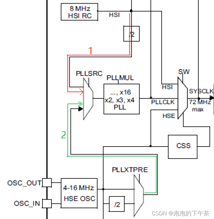
下图表示配置为PLL输入来源为不分频的HSE,经过PLL9倍频后输出PLLCLK作为系统时钟。
a)PLL相关寄存器
Clock control register (RCC_CR)——时钟控制寄存器
Bit 25 PLLRDY: PLL clock ready flag
Set by hardware to indicate that the PLL is locked.
0: PLL unlocked
1: PLL locked
Bit 24 PLLON: PLL enableSet and cleared by software to enable PLL.
Cleared by hardware when entering Stop or Standby mode. This bit can not be reset if the
PLL clock is used as system clock or is selected to become the system clock.
0: PLL OFF
1: PLL ON
Clock configuration register (RCC_CFGR)——时钟配置寄存器
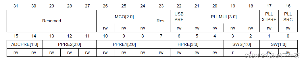
Bits 21:18 PLLMUL: PLL multiplication factor
These bits are written by software to define the PLL multiplication factor. These bits can be
written only when PLL is disabled.
Caution: The PLL output frequency must not exceed 72 MHz.
0000: PLL input clock x 2
0001: PLL input clock x 3
0010: PLL input clock x 4
0011: PLL input clock x 5
0100: PLL input clock x 6
0101: PLL input clock x 7
0110: PLL input clock x 8
0111: PLL input clock x 9
1000: PLL input clock x 10
1001: PLL input clock x 11
1010: PLL input clock x 12
1011: PLL input clock x 13
1100: PLL input clock x 14
1101: PLL input clock x 15
1110: PLL input clock x 16
1111: PLL input clock x 16
Bit 17 PLLXTPRE: HSE divider for PLL entry
Set and cleared by software to divide HSE before PLL entry. This bit can be written only
when PLL is disabled.
0: HSE clock not divided
1: HSE clock divided by 2
Bit 16 PLLSRC: PLL entry clock source
Set and cleared by software to select PLL clock source. This bit can be written only when
PLL is disabled.
0: HSI oscillator clock / 2 selected as PLL input clock
1: HSE oscillator clock selected as PLL input clock
b)PLL初始化(hal库)
/*-------------------------------- PLL Configuration -----------------------*/
/* Check the parameters */
assert_param(IS_RCC_PLL(RCC_OscInitStruct->PLL.PLLState));
if ((RCC_OscInitStruct->PLL.PLLState) != RCC_PLL_NONE)
{
//如果系统时钟源不是来自PLLCLK且PLL new state is RCC_PLL_ON,则先将RCC_CR寄存器的PLLON位置0
/* Check if the PLL is used as system clock or not */
if (__HAL_RCC_GET_SYSCLK_SOURCE() != RCC_SYSCLKSOURCE_STATUS_PLLCLK)
{
if ((RCC_OscInitStruct->PLL.PLLState) == RCC_PLL_ON)
{
/* Check the parameters */
assert_param(IS_RCC_PLLSOURCE(RCC_OscInitStruct->PLL.PLLSource));
assert_param(IS_RCC_PLL_MUL(RCC_OscInitStruct->PLL.PLLMUL));
/* Disable the main PLL. */
__HAL_RCC_PLL_DISABLE();
/* Get Start Tick */
tickstart = HAL_GetTick();
/* Wait till PLL is disabled */
while (__HAL_RCC_GET_FLAG(RCC_FLAG_PLLRDY) != RESET)
{
if ((HAL_GetTick() - tickstart) > PLL_TIMEOUT_VALUE)
{
return HAL_TIMEOUT;
}
}
/* Configure the HSE prediv factor --------------------------------*/
/* It can be written only when the PLL is disabled. Not used in PLL source is different than HSE */
//判断PLL的时钟输入是否是HSE,如果是则设置RCC_CFGR寄存器的PLLXTPRE位确定HSE是否分频后再作为PLL的输入时钟
if (RCC_OscInitStruct->PLL.PLLSource == RCC_PLLSOURCE_HSE)
{
/* Check the parameter */
assert_param(IS_RCC_HSE_PREDIV(RCC_OscInitStruct->HSEPredivValue));
#if defined(RCC_CFGR2_PREDIV1SRC)
assert_param(IS_RCC_PREDIV1_SOURCE(RCC_OscInitStruct->Prediv1Source));
/* Set PREDIV1 source */
SET_BIT(RCC->CFGR2, RCC_OscInitStruct->Prediv1Source);
#endif /* RCC_CFGR2_PREDIV1SRC */
/* Set PREDIV1 Value */
__HAL_RCC_HSE_PREDIV_CONFIG(RCC_OscInitStruct->HSEPredivValue);
}
/* Configure the main PLL clock source and multiplication factors. */
//在RCC_CFGR寄存器的PLLSRC位和PLLMUL位设置PLL的时钟来源和倍频系数
__HAL_RCC_PLL_CONFIG(RCC_OscInitStruct->PLL.PLLSource,
RCC_OscInitStruct->PLL.PLLMUL);
//将RCC_CR寄存器的PLLON位置1
/* Enable the main PLL. */
__HAL_RCC_PLL_ENABLE();
/* Get Start Tick */
tickstart = HAL_GetTick();
/* Wait till PLL is ready */
while (__HAL_RCC_GET_FLAG(RCC_FLAG_PLLRDY) == RESET)
{
if ((HAL_GetTick() - tickstart) > PLL_TIMEOUT_VALUE)
{
return HAL_TIMEOUT;
}
}
}
//如果PLL new state is RCC_PLL_OFF,则将RCC_CR寄存器的PLLON位置0
else
{
/* Disable the main PLL. */
__HAL_RCC_PLL_DISABLE();
/* Get Start Tick */
tickstart = HAL_GetTick();
/* Wait till PLL is disabled */
while (__HAL_RCC_GET_FLAG(RCC_FLAG_PLLRDY) != RESET)
{
if ((HAL_GetTick() - tickstart) > PLL_TIMEOUT_VALUE)
{
return HAL_TIMEOUT;
}
}
}
}
else
{
//如果PLLCLK是系统时钟源且PLL new state is RCC_PLL_OFF,则返回错误
/* Check if there is a request to disable the PLL used as System clock source */
if ((RCC_OscInitStruct->PLL.PLLState) == RCC_PLL_OFF)
{
return HAL_ERROR;
}
else
{
/* Do not return HAL_ERROR if request repeats the current configuration */
pll_config = RCC->CFGR;
if ((READ_BIT(pll_config, RCC_CFGR_PLLSRC) != RCC_OscInitStruct->PLL.PLLSource) ||
(READ_BIT(pll_config, RCC_CFGR_PLLMULL) != RCC_OscInitStruct->PLL.PLLMUL))
{
return HAL_ERROR;
}
}
}
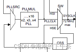
}3.3 SYSCLK
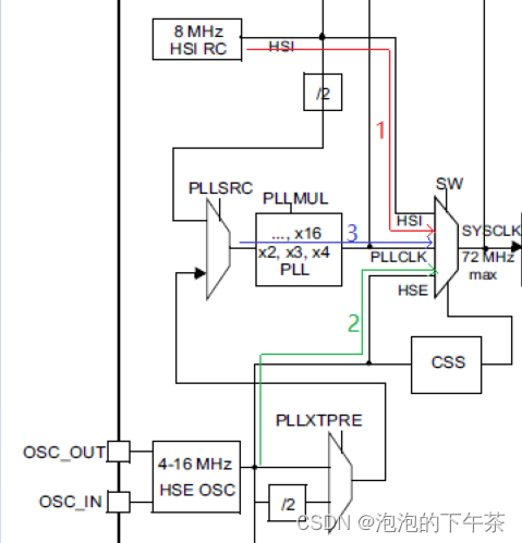
3.3.1 sysclk的输入
系统时钟sysclk有三个来源,分别是HSI、HSE和PLLCLK(由HSE或者HSI变频得到),最大为72MHz,如下图所示。
a)系统时钟源相关寄存器
Clock configuration register (RCC_CFGR)——时钟配置寄存器
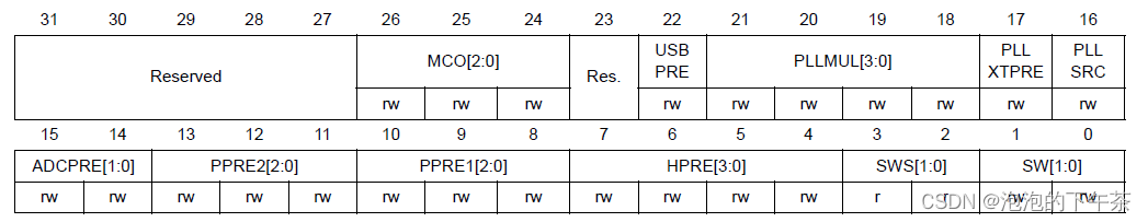
Bits 3:2 SWS: System clock switch status
Set and cleared by hardware to indicate which clock source is used as system clock.
00: HSI oscillator used as system clock
01: HSE oscillator used as system clock
10: PLL used as system clock
11: not applicable
Bits 1:0 SW: System clock switch
Set and cleared by software to select SYSCLK source.
Set by hardware to force HSI selection when leaving Stop and Standby mode or in case of
failure of the HSE oscillator used directly or indirectly as system clock (if the Clock Security
System is enabled).
00: HSI selected as system clock
01: HSE selected as system clock
10: PLL selected as system clock
11: not allowed
b)sysclk初始化(hal库)
  /*------------------------- SYSCLK Configuration ---------------------------*/
  if (((RCC_ClkInitStruct->ClockType) & RCC_CLOCKTYPE_SYSCLK) == RCC_CLOCKTYPE_SYSCLK)
  {
    assert_param(IS_RCC_SYSCLKSOURCE(RCC_ClkInitStruct->SYSCLKSource));

    /* HSE is selected as System Clock Source */
    if (RCC_ClkInitStruct->SYSCLKSource == RCC_SYSCLKSOURCE_HSE)
    {
      /* Check the HSE ready flag */
      if (__HAL_RCC_GET_FLAG(RCC_FLAG_HSERDY) == RESET)
      {
        return HAL_ERROR;
      }
    }
    /* PLL is selected as System Clock Source */
    else if (RCC_ClkInitStruct->SYSCLKSource == RCC_SYSCLKSOURCE_PLLCLK)
    {
      /* Check the PLL ready flag */
      if (__HAL_RCC_GET_FLAG(RCC_FLAG_PLLRDY) == RESET)
      {
        return HAL_ERROR;
      }
    }
    /* HSI is selected as System Clock Source */
    else
    {
      /* Check the HSI ready flag */
      if (__HAL_RCC_GET_FLAG(RCC_FLAG_HSIRDY) == RESET)
      {
        return HAL_ERROR;
      }
    }
    //将RCC_CFGR寄存器的SW位段根据sysclk的来源设置成对应值
    __HAL_RCC_SYSCLK_CONFIG(RCC_ClkInitStruct->SYSCLKSource);

    /* Get Start Tick */
    tickstart = HAL_GetTick();

    while (__HAL_RCC_GET_SYSCLK_SOURCE() != (RCC_ClkInitStruct->SYSCLKSource << RCC_CFGR_SWS_Pos))
    {
      if ((HAL_GetTick() - tickstart) > CLOCKSWITCH_TIMEOUT_VALUE)
      {
        return HAL_TIMEOUT;
      }
    }
  }
3.3.3 sysclk的输出
系统时钟SYSCLK经过AHB分频器分频(可选择1、2、4、8、16、64、128、256、512分频)后送给各模块使用。AHB分频的时钟主要送给五大模块使用。
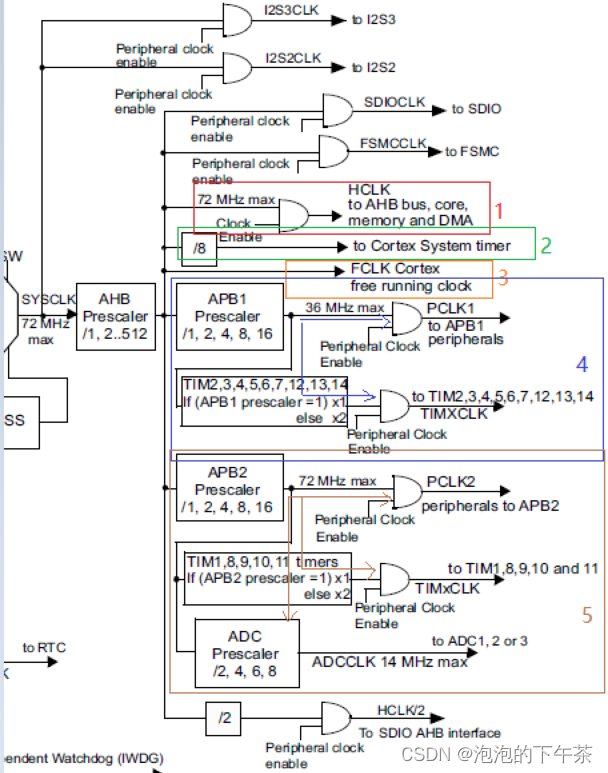
①送给AHB总线、内核、内存和DMA使用的HCLK时钟;
②通过8分频后送给Cortex的系统定时器时钟。
③直接送给Cortex的空闲运行时钟FCLK。
④送给APB1分频器(APB1分频器可选择1、2、4、8、16分频)。经APB1分频器分频后输出两路,一路提供APB1外设(低速外设)使用(PCLK1,最大频率36MHz),另一路送给通用定时器使用。。
⑤送给APB2分频器(APB2分频器可选择1、2、4、8、16分频)。经APB2分频器分频后输出三路,一路供APB2外设(高速外设)使用(PCLK2,最大频率72MHz),一路送给高级定时器1和8使用,还有一路输出给ADC分频器,ADC分频器分频后给ADC模块提供时钟。
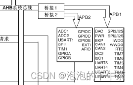
其中连接到APB1总线上的外设由DAC、CAN、IWDG、UART2-5、TIM2-7等;连接到APB2总线上的外设由ADC、USART1、TIM1、TIM8、GPIO等,如上图所示。
另外注意,如图所示很多是带有使能端控制的,使用对应外设时需要先使能时钟,如APB1、APB2、AHB总线等。
a)系统时钟输出相关寄存器
Clock configuration register (RCC_CFGR)——时钟配置寄存器
Bits 15:14 ADCPRE: ADC prescaler
Set and cleared by software to select the frequency of the clock to the ADCs.
00: PCLK2 divided by 2
01: PCLK2 divided by 4
10: PCLK2 divided by 6
11: PCLK2 divided by 8
Bits 13:11 PPRE2: APB high-speed prescaler (APB2)
Set and cleared by software to control the division factor of the APB high-speed clock
(PCLK2).
0xx: HCLK not divided
100: HCLK divided by 2
101: HCLK divided by 4
110: HCLK divided by 8
111: HCLK divided by 16
Bits 10:8 PPRE1: APB low-speed prescaler (APB1)
Set and cleared by software to control the division factor of the APB low-speed clock
(PCLK1).
Warning: the software has to set correctly these bits to not exceed 36 MHz on this domain.
0xx: HCLK not divided
100: HCLK divided by 2
101: HCLK divided by 4
110: HCLK divided by 8
111: HCLK divided by 16
Bits 7:4 HPRE: AHB prescaler
Set and cleared by software to control the division factor of the AHB clock.
0xxx: SYSCLK not divided
1000: SYSCLK divided by 2
1001: SYSCLK divided by 4
1010: SYSCLK divided by 8
1011: SYSCLK divided by 16
1100: SYSCLK divided by 64
1101: SYSCLK divided by 128
1110: SYSCLK divided by 256
b)HCLK、PCLK初始化(hal库)
/*-------------------------- HCLK Configuration --------------------------*/
if (((RCC_ClkInitStruct->ClockType) & RCC_CLOCKTYPE_HCLK) == RCC_CLOCKTYPE_HCLK)
{
//先将APB1和APB2分频器设置成最大值,防止我们修改AHB分频器值时产生的时钟频率再经过APB分频器后超过最大时钟频率限制
/* Set the highest APBx dividers in order to ensure that we do not go through
a non-spec phase whatever we decrease or increase HCLK. */
if (((RCC_ClkInitStruct->ClockType) & RCC_CLOCKTYPE_PCLK1) == RCC_CLOCKTYPE_PCLK1)
{
MODIFY_REG(RCC->CFGR, RCC_CFGR_PPRE1, RCC_HCLK_DIV16);
}
if (((RCC_ClkInitStruct->ClockType) & RCC_CLOCKTYPE_PCLK2) == RCC_CLOCKTYPE_PCLK2)
{
MODIFY_REG(RCC->CFGR, RCC_CFGR_PPRE2, (RCC_HCLK_DIV16 << 3));
}
//将RCC_CFGR寄存器的HPRE位段置成相应选择
/* Set the new HCLK clock divider */
assert_param(IS_RCC_HCLK(RCC_ClkInitStruct->AHBCLKDivider));
MODIFY_REG(RCC->CFGR, RCC_CFGR_HPRE, RCC_ClkInitStruct->AHBCLKDivider);
}
//配置完AHB后再配置PCK1和PLCK2,再分别将RCC_CFGR寄存器的PPRE1和PPRE2位段置成相应选择
/*-------------------------- PCLK1 Configuration ---------------------------*/
if (((RCC_ClkInitStruct->ClockType) & RCC_CLOCKTYPE_PCLK1) == RCC_CLOCKTYPE_PCLK1)
{
assert_param(IS_RCC_PCLK(RCC_ClkInitStruct->APB1CLKDivider));
MODIFY_REG(RCC->CFGR, RCC_CFGR_PPRE1, RCC_ClkInitStruct->APB1CLKDivider);
}
/*-------------------------- PCLK2 Configuration ---------------------------*/
if (((RCC_ClkInitStruct->ClockType) & RCC_CLOCKTYPE_PCLK2) == RCC_CLOCKTYPE_PCLK2)
{
assert_param(IS_RCC_PCLK(RCC_ClkInitStruct->APB2CLKDivider));
MODIFY_REG(RCC->CFGR, RCC_CFGR_PPRE2, ((RCC_ClkInitStruct->APB2CLKDivider) << 3));
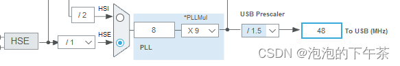
}3.4 USBCLK
STM32中的USB模块,该时钟源只能从PLL输出端获取(唯一的),当需要使用USB模块时,PLL必须使能,并且需要配置其时钟频率为48MHz。如果经过PLL倍频后输出72MHZ,需要再经USB预分频器1.5分频后再供给USB使用,如下图所示。
相关寄存器
Clock configuration register (RCC_CFGR)——时钟配置寄存器
Bit 22 USBPRE: USB prescaler
Set and cleared by software to generate 48 MHz USB clock. This bit must be valid before
enabling the USB clock in the RCC_APB1ENR register. This bit can’t be reset if the USB
clock is enabled.
0: PLL clock is divided by 1.5
1: PLL clock is not divided
3.5 CCS(Clock security system)
时钟安全系统可以通过软件被激活。一旦其被激活,时钟监测器将在HSE振荡器启动延迟后被使能,并在HSE时钟关闭后关闭。 如果HSE时钟发生故障,HSE振荡器被自动关闭,时钟失效事件将被送到高级定时器(TIM1和TIM8)的break input,并产生时钟安全中断CSSI(Clock Security System Interrupt),允许软件完成营救操作。此CSSI中断连接到Cortex™-M3的NMI中断(不可屏蔽中断)。 注意: 一旦CSS被激活,并且HSE时钟出现故障,CSS中断就产生,并且NMI(Non-Maskable Interrupt))也自动产生。NMI将被不断执行,直到CSS中断挂起位被清除。因此,在NMI的处理程序中必须通过设置时钟中断寄存器(RCC_CIR)里的CSSC位来清除CSS中断。如果HSE振荡器被直接或间接地作为系统时钟,(间接的意思是:它被作为PLL输入时钟,并且PLL时钟被作为系统时钟),时钟故障将导致系统时钟自动切换到HSI振荡器,同时外部HSE振荡器被关闭。在时钟失效时,如果HSE振荡器时钟(被分频或未被分频)是用作系统时钟的PLL的输入时钟,PLL也将被关闭。
a)CCS功能相关寄存器
Clock control register (RCC_CR)——时钟控制寄存器
Bit 19 CSSON: Clock security system enable
Set and cleared by software to enable the clock security system. When CSSON is set, the
clock detector is enabled by hardware when the HSE oscillator is ready, and disabled by
hardware if a HSE clock failure is detected.
0: Clock detector OFF
1: Clock detector ON (Clock detector ON if the HSE oscillator is ready , OFF if not).
b)CCS功能使能和失能接口
Clock interrupt register (RCC_CIR)——时钟中断寄存器
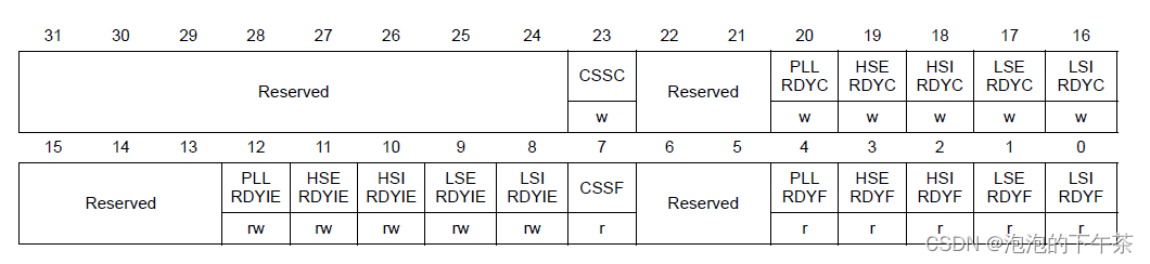
Bit 23 CSSC: Clock security system interrupt clear
This bit is set by software to clear the CSSF flag.
0: No effect
1: Clear CSSF flag
Bit 7 CSSF: Clock security system interrupt flag
Set by hardware when a failure is detected in the external 4-16 MHz oscillator.
Cleared by software setting the CSSC bit.
0: No clock security interrupt caused by HSE clock failure
1: Clock security interrupt caused by HSE clock failure
b)CSS功能相关接口(hal库)
void HAL_RCC_EnableCSS(void)
{
*(__IO uint32_t *) RCC_CR_CSSON_BB = (uint32_t)ENABLE;
}
void HAL_RCC_DisableCSS(void)
{
*(__IO uint32_t *) RCC_CR_CSSON_BB = (uint32_t)DISABLE;
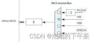
}3.6 MOC(microcontroller clock output)
STM32可以选择一个时钟信号输出到MCO脚(PA8)上供外部使用,可以选择为PLL输出的2分频、HSI、HSE、或者系统时钟。在MOC上的输出时钟必须小于50MHZ(IO端口的最大输出速度)。
a)MOC功能相关寄存器
Clock configuration register (RCC_CFGR)——时钟配置寄存器
Bits 26:24 MCO: Microcontroller clock output
Set and cleared by software.
0xx: No clock
100: System clock (SYSCLK) selected
101: HSI clock selected
110: HSE clock selected
111: PLL clock divided by 2 selected
b)MOC配置接口(hal库)
/**
  * @brief  Selects the clock source to output on MCO pin.
  * @note   MCO pin should be configured in alternate function mode.
  * @param  RCC_MCOx specifies the output direction for the clock source.
  *          This parameter can be one of the following values:
  *            @arg @ref RCC_MCO1 Clock source to output on MCO1 pin(PA8).
  * @param  RCC_MCOSource specifies the clock source to output.
  *          This parameter can be one of the following values:
  *            @arg @ref RCC_MCO1SOURCE_NOCLOCK     No clock selected as MCO clock
  *            @arg @ref RCC_MCO1SOURCE_SYSCLK      System clock selected as MCO clock
  *            @arg @ref RCC_MCO1SOURCE_HSI         HSI selected as MCO clock
  *            @arg @ref RCC_MCO1SOURCE_HSE         HSE selected as MCO clock
  @if STM32F105xC
  *            @arg @ref RCC_MCO1SOURCE_PLLCLK       PLL clock divided by 2 selected as MCO source
  *            @arg @ref RCC_MCO1SOURCE_PLL2CLK      PLL2 clock selected as MCO source
  *            @arg @ref RCC_MCO1SOURCE_PLL3CLK_DIV2 PLL3 clock divided by 2 selected as MCO source
  *            @arg @ref RCC_MCO1SOURCE_EXT_HSE      XT1 external 3-25 MHz oscillator clock selected as MCO source
  *            @arg @ref RCC_MCO1SOURCE_PLL3CLK      PLL3 clock selected as MCO source
  @endif
  @if STM32F107xC
  *            @arg @ref RCC_MCO1SOURCE_PLLCLK       PLL clock divided by 2 selected as MCO source
  *            @arg @ref RCC_MCO1SOURCE_PLL2CLK      PLL2 clock selected as MCO source
  *            @arg @ref RCC_MCO1SOURCE_PLL3CLK_DIV2 PLL3 clock divided by 2 selected as MCO source
  *            @arg @ref RCC_MCO1SOURCE_EXT_HSE XT1  external 3-25 MHz oscillator clock selected as MCO source
  *            @arg @ref RCC_MCO1SOURCE_PLL3CLK      PLL3 clock selected as MCO source
  @endif
  * @param  RCC_MCODiv specifies the MCO DIV.
  *          This parameter can be one of the following values:
  *            @arg @ref RCC_MCODIV_1 no division applied to MCO clock
  * @retval None
  */
void HAL_RCC_MCOConfig(uint32_t RCC_MCOx, uint32_t RCC_MCOSource, uint32_t RCC_MCODiv)
{
  GPIO_InitTypeDef gpio = {0U};

  /* Check the parameters */
  assert_param(IS_RCC_MCO(RCC_MCOx));
  assert_param(IS_RCC_MCODIV(RCC_MCODiv));
  assert_param(IS_RCC_MCO1SOURCE(RCC_MCOSource));

  /* Prevent unused argument(s) compilation warning */
  UNUSED(RCC_MCOx);
  UNUSED(RCC_MCODiv);

  /* Configure the MCO1 pin in alternate function mode */
  gpio.Mode      = GPIO_MODE_AF_PP;
  gpio.Speed     = GPIO_SPEED_FREQ_HIGH;
  gpio.Pull      = GPIO_NOPULL;
  gpio.Pin       = MCO1_PIN;

  /* MCO1 Clock Enable */
  MCO1_CLK_ENABLE();

  HAL_GPIO_Init(MCO1_GPIO_PORT, &gpio);

  /* Configure the MCO clock source */
  __HAL_RCC_MCO1_CONFIG(RCC_MCOSource, RCC_MCODiv);
}
四、最后
各位大佬觉得有用的,点赞加关注,出门不迷路。。。哈哈


 被折叠的 条评论
为什么被折叠?
被折叠的 条评论
为什么被折叠?
 到【灌水乐园】发言


