


实验内容
使用状态机实现系列检测器,状态机设为s0~s8共9个状态,当状态机进入S8状态时表示前 面的检测都正确,检测到所预制的系列。状态机输出1,其他状态输出都为0。
本实验设计的检测器要求能够检测到序列“11010011”。当这一串序列数高位在前(左移)串行进 入检测器后,若此数与预置的密码数相同,则状态机输出sout=1,否则输出sout=0
实验步骤
1新建工程,并新建.v文件
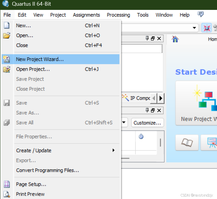
新建工程
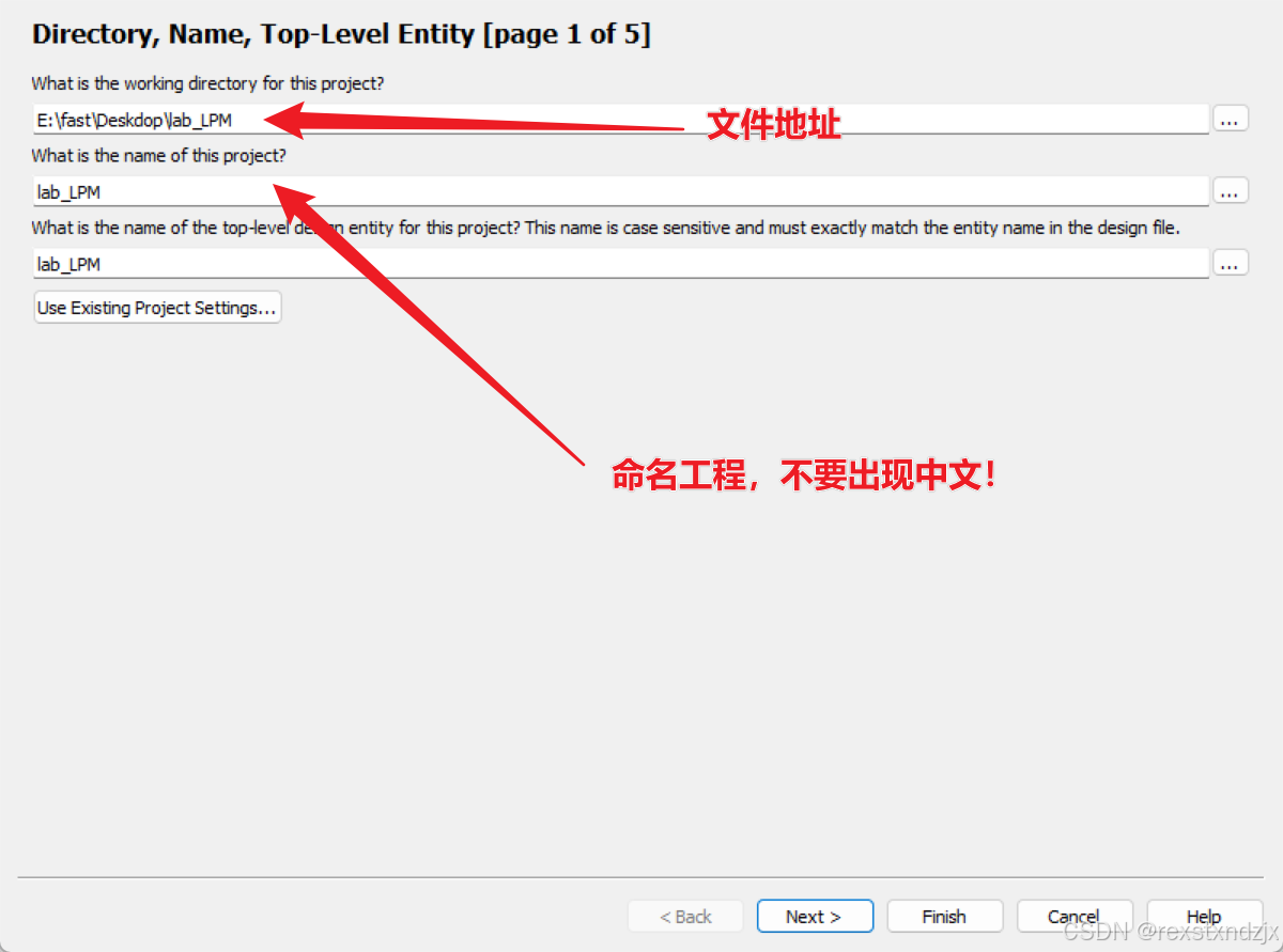
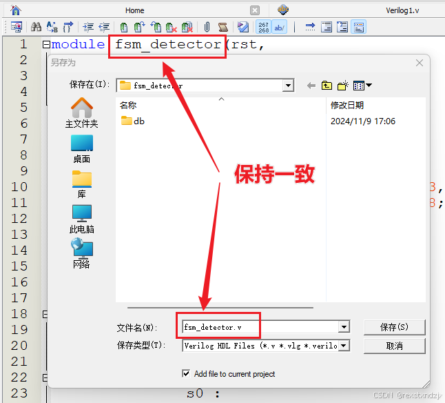
注意文件命名为fsm_detector !!!
一直点next,直到出现下面的界面
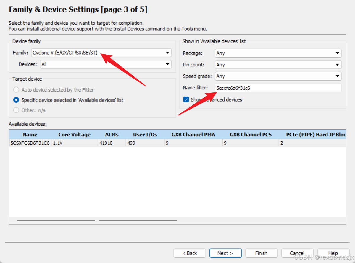
芯片选择5csxfc6d6f31c6
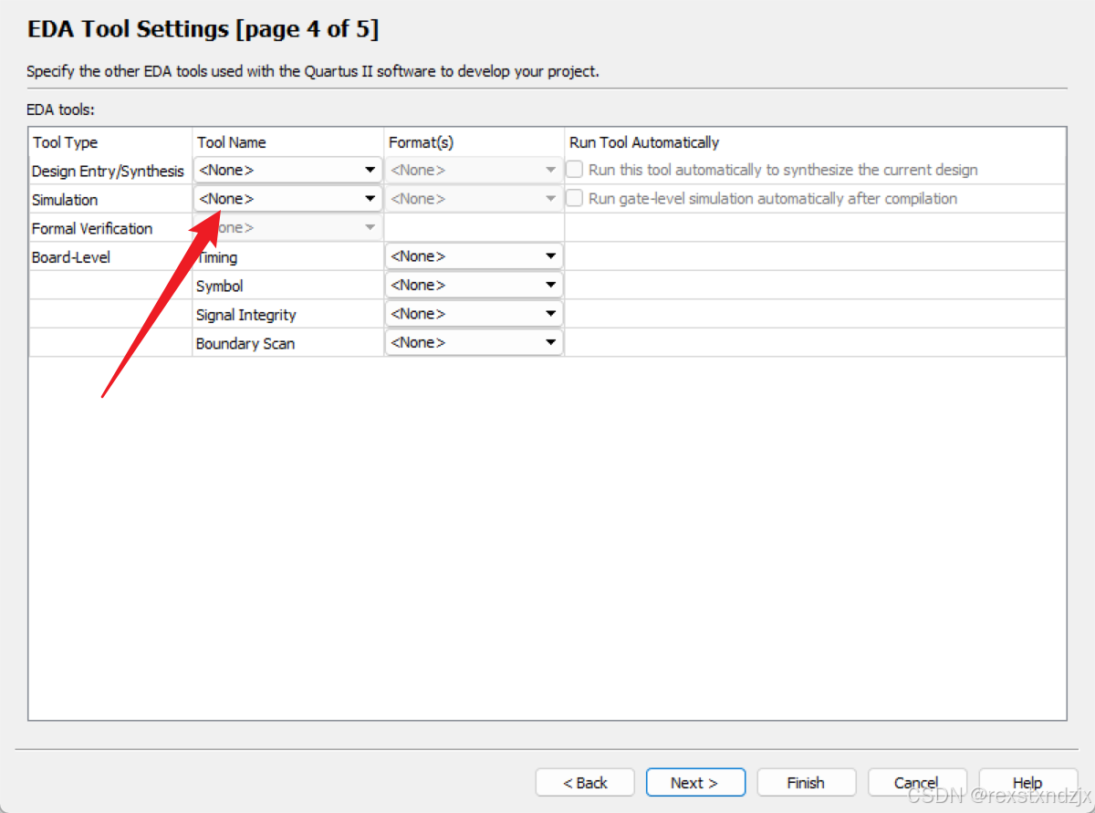
这里选择None,然后完成
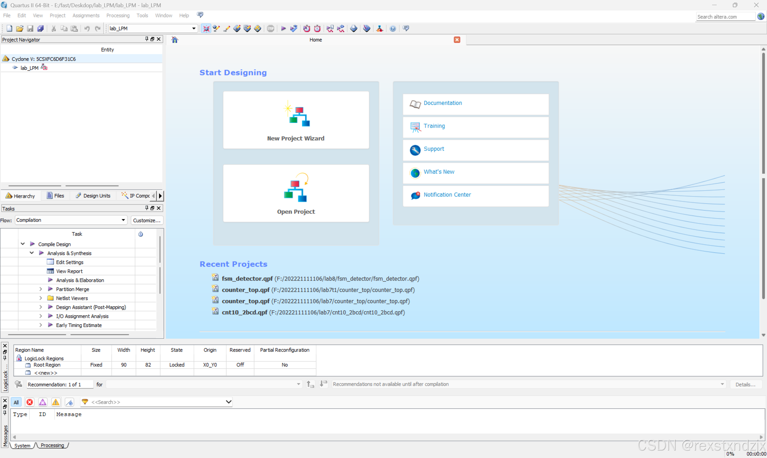
出现如下界面
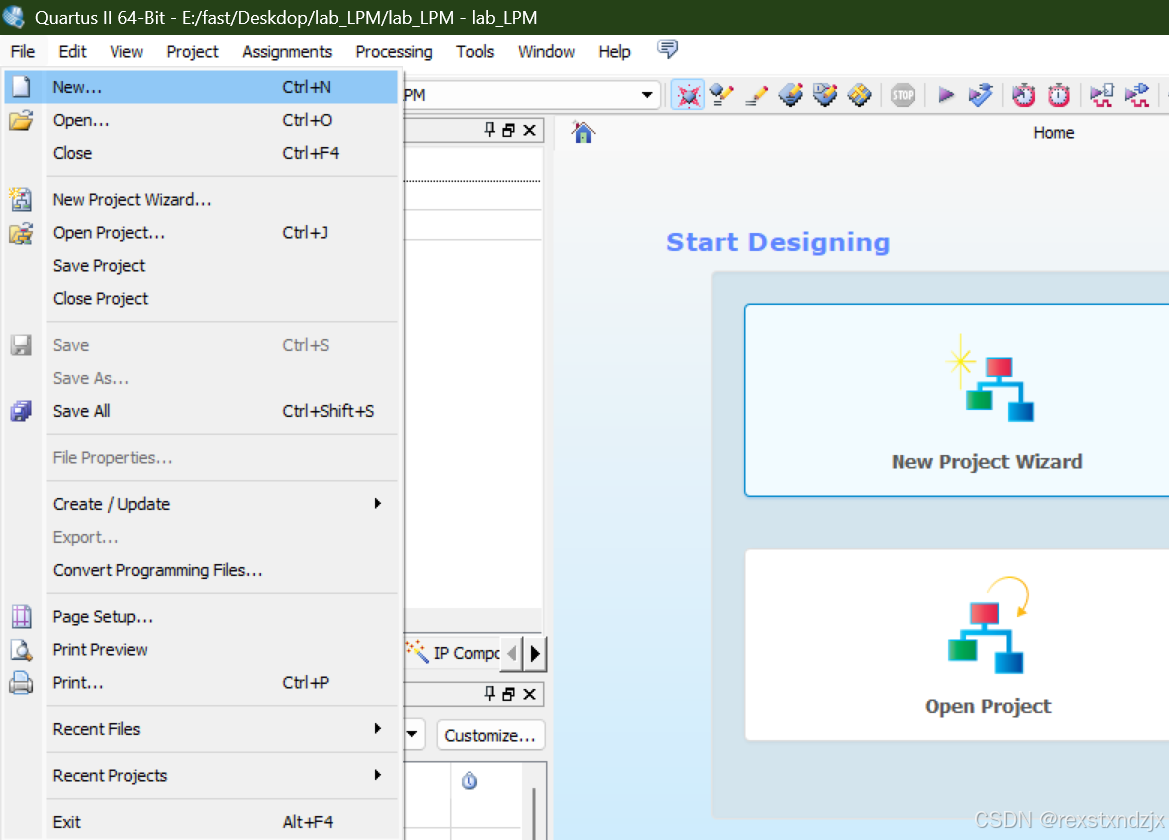
点击file-->new
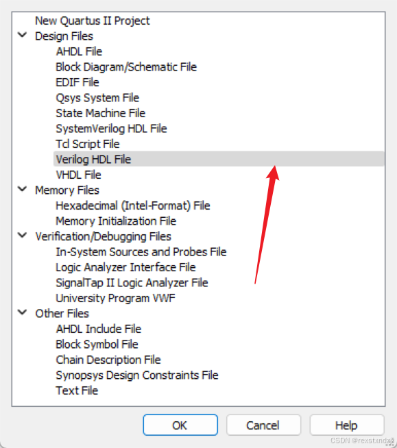
在文件中加入代码 :
module fsm_detector(rst,
							clk,
							din,
							sout,
							fsm_state);
	input 			rst, clk;
	input 			din;
	output 			sout;
	output			[3:0] fsm_state;
	parameter s0 = 0, s1 = 1, s2 = 2, s3 = 3, s4 = 4;
	parameter s5 = 5, s6 = 6, s7 = 7, s8 = 8;

	reg [3:0] state;

	assign fsm_state =state;

	always @ (posedge rst or posedge clk)
		begin
			if(rst)
				state <= s0;
			else
				case(state)
					s0 :
						if (din == 1'b1)
							state <= s1;
						else
							state <= s0;
					s1 :
						if (din == 1'b1)
							state <= s2;
						else
							state <= s0;
					s2 :
						if (din == 1'b0)
							state <= s3;
						else
							state <= s0;
					s3 :
						if (din == 1'b1)
							state <= s4;
						else
							state <= s0;
					s4 :
						if (din == 1'b0)
							state <= s5;
						else
							state <= s0;
					s5 :
						if (din == 1'b0)
							state <= s6;
						else
							state <= s0;
					s6 :
						if (din == 1'b1)
							state <= s7;
						else
							state <= s0;
					s7 :
						if (din == 1'b1)
							state <= s8;
						else
							state <= s0;
					s8 :
						state <= s0;
					default :
						state <= s0;
				endcase
		end
		assign sout = (state == s8);

endmodule
保存文件
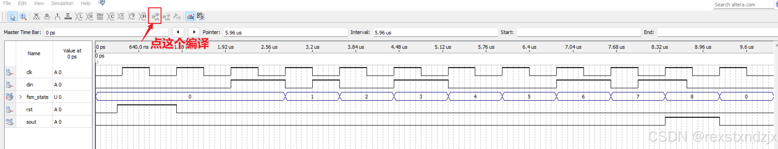
编译文件
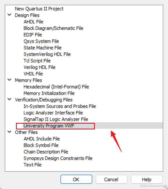
新建.vwf仿真文件
添加信号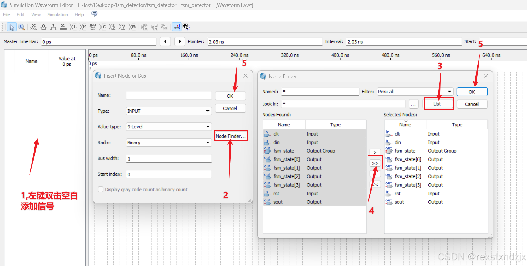
设置仿真参数:
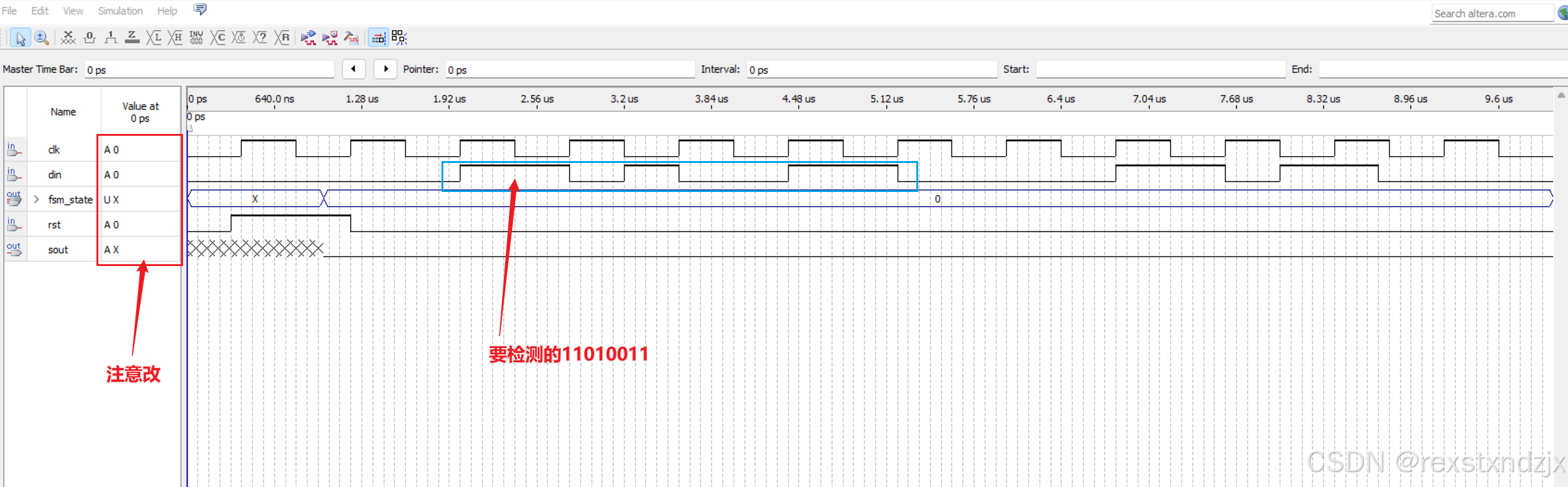
仿真时在波形文件中加入内部的状态机当前状态state,仿真时间设置为10us,时钟周期设置为 800ns,注意din的波形画法:din的变化周期应该和时钟clk相同,是800ns,但其变化应该是在时钟 的下降沿。因为状态机是在上升沿采样输入数据。
前提已经说过我们要检测11010011,故din波形时要按照11010011来画!
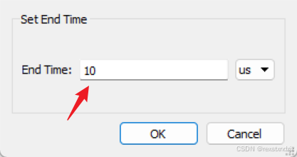
设置结束时间
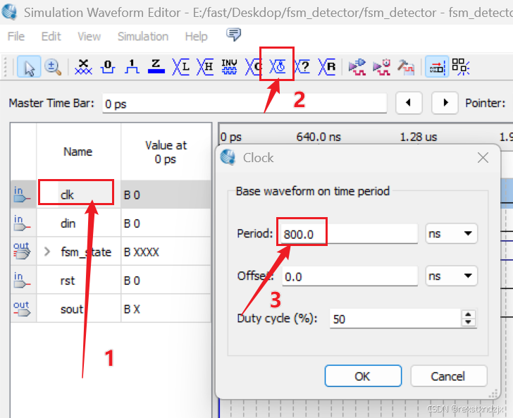
设置clk
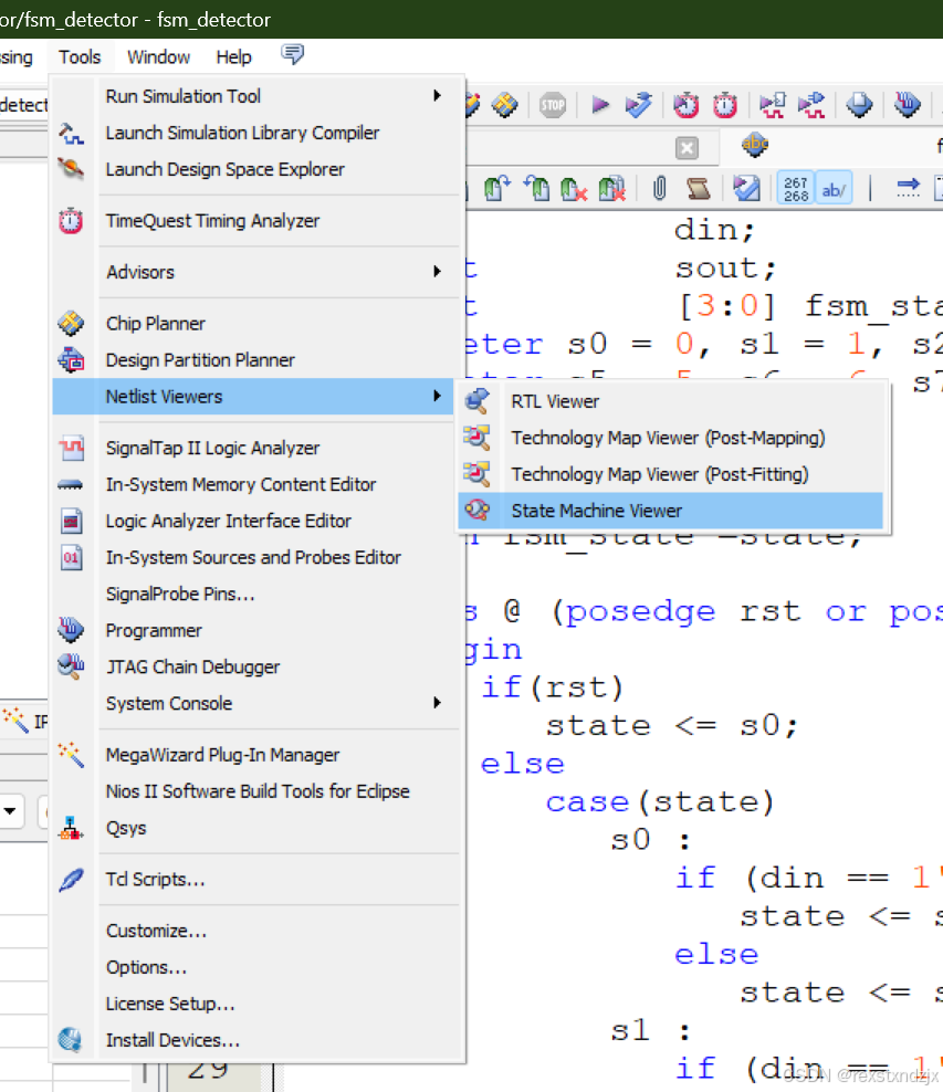
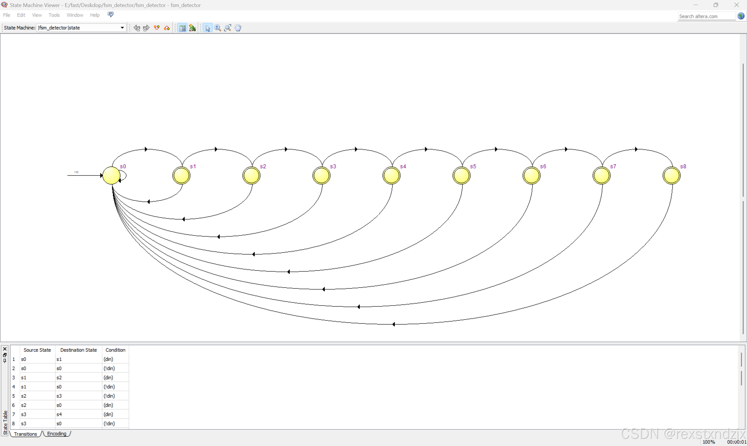
查看状态转移图
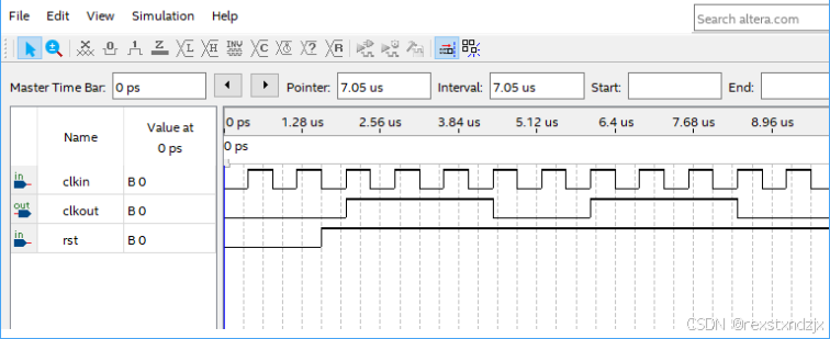
试用状态机设计一个5分频的分频器,占空比为3/5。
代码如下
module div_5 ( clkin, rst, clkout );
input clkin, rst;
output reg clkout;
reg [2:0] step;
always @(posedge clkin or negedge rst)
if(!rst)
  step <= 3'b000;
else
   begin
   case (step)
    3'b000: step <= 3'b001;
    3'b001: step <= 3'b011;
    3'b011: step <= 3'b100;
    3'b100: step <= 3'b010;
    3'b010: step <= 3'b000;
    default: step <= 3'b000;
   endcase
   end

always @(posedge clkin or negedge rst)
if(!rst)
  clkout <= 1'b0;
else
  clkout <= (step != 3'b100) & (step != 3'b010);

endmodule
仿真波形


 被折叠的 条评论
为什么被折叠?
被折叠的 条评论
为什么被折叠?
 到【灌水乐园】发言


