


一、了解串口协议和RS-232标准,以及RS232电平与TTL电平的区别;了解"USB/TTL转232"模块(以CH340芯片模块为例)的工作原理
串口协议是一种计算机通信协议,用于实现设备间的数据交换。它是一种比较古老但仍然广泛使用的通信方式,特别是在工业控制和嵌入式系统中。串口通信通常是指串行通信,与并行通信相对,数据是一位接一位按顺序传送的。
RS-232电平与TTL电平的主要区别在于它们的电压表示方式:
RS-232电平:使用较高的电压,通常在-3V到-15V之间表示逻辑“1”,在+3V到+15V之间表示逻辑“0”。这种高电压电平设计是为了在较长距离的通信中提供更好的抗噪声能力。
TTL电平:使用较低的电压,通常在0V到0.8V之间表示逻辑“0”,在2.0V到5V之间表示逻辑“1”。TTL电平主要用于集成电路内部,或电路板上的近距离通信。
由于RS-232和TTL电平不兼容,当需要在两种电平之间进行通信时,需要使用电平转换器进行转换。常见的电平转换器有MAX232等芯片,它们能够将TTL电平转换为RS-232电平,反之亦然。
二、掌握TM32的标准库开发的基本方法;掌握UART串口通信程序开发基本方法
(一)标准库方式完成LED的点灯
代码:
#include "stm32f10x.h" // 包含STM32F10x系列微控制器的头文件

int main() {
    // 使能GPIOA的时钟
    RCC->APB2ENR |= RCC_APB2ENR_IOPAEN;
    // 清除PA4的模式和配置,准备设置新的模式
    GPIOA->CRL &= ~(GPIO_CRL_MODE4 | GPIO_CRL_CNF4);
    // 将PA4设置为输出模式,最大速度10MHz
    GPIOA->CRL |= GPIO_CRL_MODE4_0;

    while(1) {
        // 将PA4设置为高电平,点亮LED
        GPIOA->BSRR = GPIO_BSRR_BS4;
        // 将PA4设置为低电平,熄灭LED
        GPIOA->BRR = GPIO_BRR_BR4;
    }
}
实际效果:
![[标准库点亮一个LED 1.jpg]]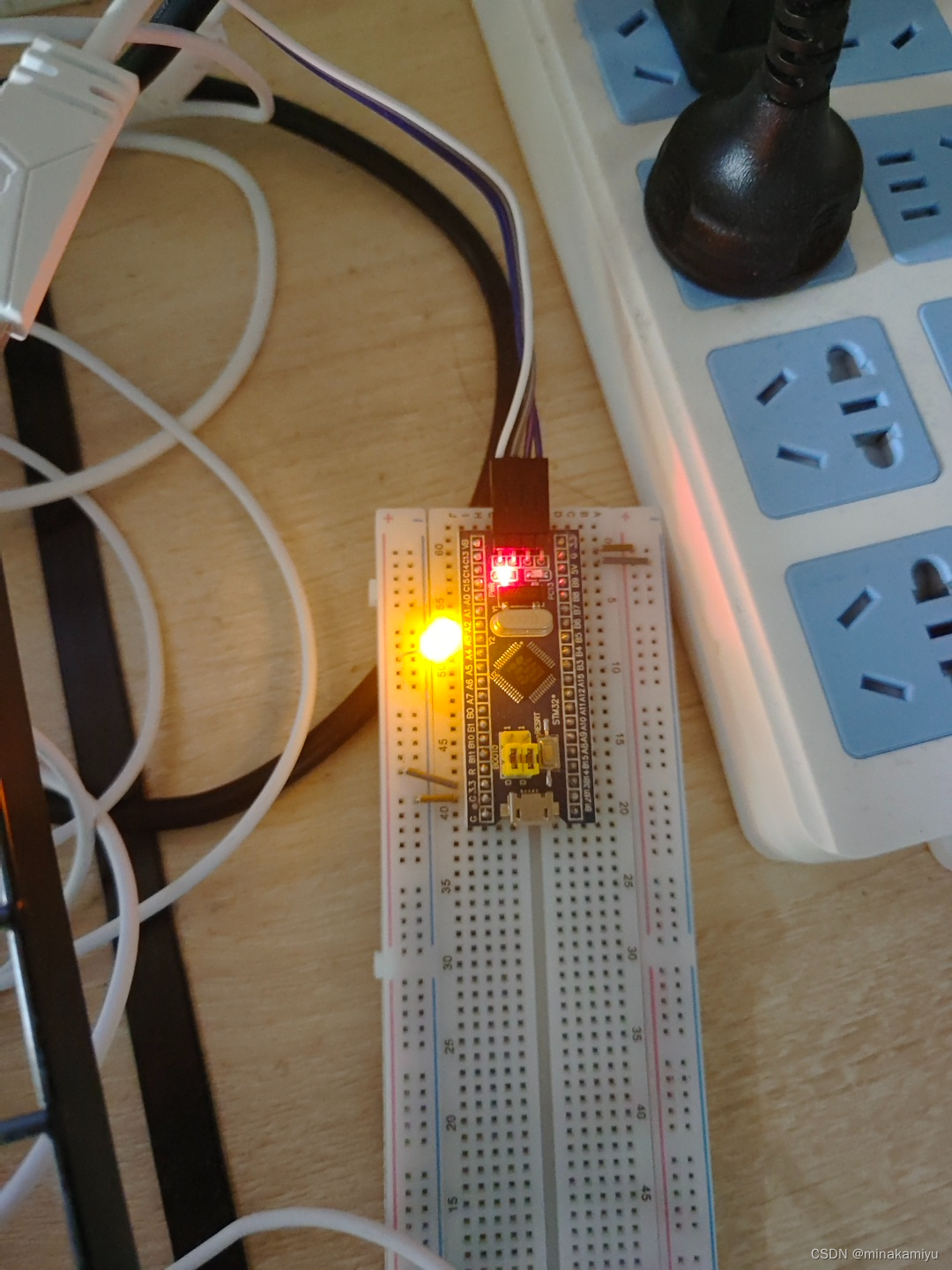
(二)STM32系统给上位机(win10)连续发送“hello windows!”,win10采用“串口助手”工具接收
main.c的代码:
#include "stm32f10x.h"
#include "misc.h"
#include <string.h>  // 包含 string.h 以使用 strlen

void USART_Configuration(void) {
    USART_InitTypeDef USART_InitStructure;
    GPIO_InitTypeDef GPIO_InitStructure;

    // 打开GPIO与USART端口的时钟
    RCC_APB2PeriphClockCmd(RCC_APB2Periph_GPIOA | RCC_APB2Periph_USART1, ENABLE);

    // 配置USART1 Tx (PA.09)为复用推挽输出
    GPIO_InitStructure.GPIO_Pin = GPIO_Pin_9;
    GPIO_InitStructure.GPIO_Mode = GPIO_Mode_AF_PP;
    GPIO_InitStructure.GPIO_Speed = GPIO_Speed_50MHz;
    GPIO_Init(GPIOA, &GPIO_InitStructure);

    // 配置USART
    USART_InitStructure.USART_BaudRate = 9600;
    USART_InitStructure.USART_WordLength = USART_WordLength_8b;
    USART_InitStructure.USART_StopBits = USART_StopBits_1;
    USART_InitStructure.USART_Parity = USART_Parity_No;
    USART_InitStructure.USART_HardwareFlowControl = USART_HardwareFlowControl_None;
    USART_InitStructure.USART_Mode = USART_Mode_Tx;
    USART_Init(USART1, &USART_InitStructure);

    // 使能USART
    USART_Cmd(USART1, ENABLE);
}

void Delay(__IO uint32_t nCount) {  // 简单的延时函数
    for(; nCount != 0; nCount--);
}

int main(void) {
    SystemInit(); // 初始化系统时钟
    USART_Configuration(); // 配置串口

    char *str = "hello windows!\r\n";   // 添加换行符
    while(1) {
        for(uint32_t i = 0; i < strlen(str); i++) {
            // 等待发送数据寄存器为空
            while(USART_GetFlagStatus(USART1, USART_FLAG_TXE) == RESET);
            // 发送一个字节数据到USART1
            USART_SendData(USART1, str[i]);
        }
        // 延时
        Delay(5000000);  // 增加延时时间,以便观察效果
    }
}
keil中调试,测试usart1的状态,正常输出了该有的内容
![![[Pasted image 20240512175135.png]]](https://img-blog.csdnimg.cn/direct/4b29257432334efc9343940251286355.png)
下面进行实物实验:
任务2
(三)STM32以查询方式接收上位机(win10)串口发来的数据,如果接收到“Y”则点亮链接到stm32上的一个LED灯,接收到“N”则熄灭LED灯
main.c的代码:
#include "stm32f10x.h"

void USART_Configuration(void) {
    USART_InitTypeDef USART_InitStructure;
    GPIO_InitTypeDef GPIO_InitStructure;

    RCC_APB2PeriphClockCmd(RCC_APB2Periph_GPIOA | RCC_APB2Periph_USART1, ENABLE);
    GPIO_InitStructure.GPIO_Pin = GPIO_Pin_9 | GPIO_Pin_10;
    GPIO_InitStructure.GPIO_Mode = GPIO_Mode_AF_PP;
    GPIO_InitStructure.GPIO_Speed = GPIO_Speed_50MHz;
    GPIO_Init(GPIOA, &GPIO_InitStructure);

    GPIO_InitStructure.GPIO_Pin = GPIO_Pin_10;
    GPIO_InitStructure.GPIO_Mode = GPIO_Mode_IN_FLOATING;
    GPIO_Init(GPIOA, &GPIO_InitStructure);

    USART_InitStructure.USART_BaudRate = 9600;
    USART_InitStructure.USART_WordLength = USART_WordLength_8b;
    USART_InitStructure.USART_StopBits = USART_StopBits_1;
    USART_InitStructure.USART_Parity = USART_Parity_No;
    USART_InitStructure.USART_HardwareFlowControl = USART_HardwareFlowControl_None;
    USART_InitStructure.USART_Mode = USART_Mode_Rx | USART_Mode_Tx;
    USART_Init(USART1, &USART_InitStructure);

    USART_Cmd(USART1, ENABLE);
}

void GPIO_Configuration(void) {
    GPIO_InitTypeDef GPIO_InitStructure;
    RCC_APB2PeriphClockCmd(RCC_APB2Periph_GPIOB, ENABLE);

    GPIO_InitStructure.GPIO_Pin = GPIO_Pin_8;
    GPIO_InitStructure.GPIO_Mode = GPIO_Mode_Out_PP;
    GPIO_InitStructure.GPIO_Speed = GPIO_Speed_50MHz;
    GPIO_Init(GPIOB, &GPIO_InitStructure);
}

int main(void) {
    SystemInit();
    USART_Configuration();
    GPIO_Configuration();

    while (1) {
        if (USART_GetFlagStatus(USART1, USART_FLAG_RXNE) != RESET) {
            char data = USART_ReceiveData(USART1);
            if (data == 'Y') {
                GPIO_SetBits(GPIOB, GPIO_Pin_8);  // 点亮LED
            }
            if (data == 'N') {
                GPIO_ResetBits(GPIOB, GPIO_Pin_8);  // 熄灭LED
            }
        }
    }
}
实物实验:
任务3


 被折叠的 条评论
为什么被折叠?
被折叠的 条评论
为什么被折叠?
 到【灌水乐园】发言


