


文章目录
一、用stm32F103核心板的GPIOA端一管脚接一个LED,GPIOB端口一引脚接一个开关(用杜邦线模拟代替)。采用中断模式编程,当开关接高电平时,LED亮灯;接低电平时,LED灭灯
(一)代码和思路
将文件添加到keil工程中,像下图即可
![![[Pasted image 20240513222545.png]]](https://img-blog.csdnimg.cn/direct/ba9102141a9a4d99a1c646ec35e4c58d.png)
exti_key.h文件
#ifndef __EXTI_KEY_H
#define __EXTI_KEY_H
#include "stm32f10x.h"
void EXTI_Key_Init(void);
#endif
exti_key.c文件
#include "exti_key.h"
#include "misc.h"

void EXTI_Key_Init(void)
{
    GPIO_InitTypeDef GPIO_InitStructure;
    RCC_APB2PeriphClockCmd(RCC_APB2Periph_GPIOA | RCC_APB2Periph_AFIO, ENABLE);
    GPIO_InitStructure.GPIO_Pin = GPIO_Pin_9; // 将GPIO_Pin_3替换为GPIO_Pin_9,对应PA9
    GPIO_InitStructure.GPIO_Mode = GPIO_Mode_IN_FLOATING;
    GPIO_Init(GPIOA, &GPIO_InitStructure);
    NVIC_InitTypeDef NVIC_InitStructure;
    NVIC_PriorityGroupConfig(NVIC_PriorityGroup_2);
    NVIC_InitStructure.NVIC_IRQChannel = EXTI9_5_IRQn; // 对应外部中断通道
    NVIC_InitStructure.NVIC_IRQChannelPreemptionPriority = 0;
    NVIC_InitStructure.NVIC_IRQChannelSubPriority = 1;
    NVIC_InitStructure.NVIC_IRQChannelCmd = ENABLE;
    NVIC_Init(&NVIC_InitStructure);
    EXTI_InitTypeDef EXTI_InitStructure;
    EXTI_ClearITPendingBit(EXTI_Line9);
    GPIO_EXTILineConfig(GPIO_PortSourceGPIOA, GPIO_PinSource9); // 对应PA9引脚
    EXTI_InitStructure.EXTI_Line = EXTI_Line9;
    EXTI_InitStructure.EXTI_Mode = EXTI_Mode_Interrupt;
    EXTI_InitStructure.EXTI_Trigger = EXTI_Trigger_Falling;
    EXTI_InitStructure.EXTI_LineCmd = ENABLE;
    EXTI_Init(&EXTI_InitStructure);
}
main.c文件
#include "stm32f10x.h"
#include "led.h"
#include "exti_key.h"

int main(void)
{
    LED_Init();
    GPIO_ResetBits(GPIOB, GPIO_Pin_5);
    EXTI_Key_Init(); // 调用修改后的外部中断初始化函数
    while(1)
    {
    }
}

void EXTI9_5_IRQHandler(void) // 修改为对应的外部中断通道
{
    if(EXTI_GetITStatus(EXTI_Line9) != RESET) // 修改为对应的外部中断线
    {
        GPIO_WriteBit(GPIOB, GPIO_Pin_5, (BitAction)((1 - GPIO_ReadOutputDataBit(GPIOB, GPIO_Pin_5))));
        EXTI_ClearITPendingBit(EXTI_Line9); // 修改为对应的外部中断线
    }
}
思路:
- exti_key.h文件:
- 定义了一个函数
EXTI_Key_Init(),用于外部中断的初始化。
- 定义了一个函数
- exti_key.c文件:
- 在
EXTI_Key_Init()函数中进行以下操作:- 初始化GPIOA的第9个引脚(即PA9)为输入浮空状态。
- 使能GPIOA和AFIO的时钟。
- 配置外部中断线为下降沿触发。
- 配置NVIC中断优先级和使能外部中断通道。
- 执行外部中断线的配置和初始化。
- 在
- main.c文件:
- 在
main函数中:- 初始化LED和外部中断。
- 进入一个无限的循环以等待外部中断触发。
- 定义了一个
EXTI9_5_IRQHandler中断服务函数:- 当外部中断引脚(PA9)触发时,进行相关的开关操作,即切换GPIOB的Pin 5引脚的状态。
- 在
(二)运行效果和实验
![![[Pasted image 20240513223627.png]]](https://img-blog.csdnimg.cn/direct/335586ab267b45069ed88317dc1003c4.png)
实验:
12-1
尝试在main函数while循环中加入一个串口每隔1s发送一次字符的代码片段,发现按键中断对串口发送会带来一定的延迟
二、采用串口中断方式重做上周的串口通信作业
(一)当stm32接收到字符“s”时,停止持续发送“hello windows!”;当接收到字符“t”时,持续发送“hellowindows!”(提示:采用一个全局标量做信号灯)
1.代码和思路
#include "stm32f10x.h"
#include "misc.h"
#include <string.h>  // 包含 string.h 以使用 strlen

volatile uint8_t send_enabled = 0;  // 全局变量,控制发送行为

void USART_Configuration(void) {
    USART_InitTypeDef USART_InitStructure;
    GPIO_InitTypeDef GPIO_InitStructure;

    // 打开 GPIO 与 USART 端口的时钟
    RCC_APB2PeriphClockCmd(RCC_APB2Periph_GPIOA | RCC_APB2Periph_USART1, ENABLE);

    // 配置 USART1 Tx (PA.09) 为复用推挽输出
    GPIO_InitStructure.GPIO_Pin = GPIO_Pin_9;
    GPIO_InitStructure.GPIO_Mode = GPIO_Mode_AF_PP;
    GPIO_InitStructure.GPIO_Speed = GPIO_Speed_50MHz;
    GPIO_Init(GPIOA, &GPIO_InitStructure);

    // 配置 USART1 Rx (PA.10) 为浮空输入
    GPIO_InitStructure.GPIO_Pin = GPIO_Pin_10;
    GPIO_InitStructure.GPIO_Mode = GPIO_Mode_IN_FLOATING;
    GPIO_Init(GPIOA, &GPIO_InitStructure);

    // 配置 USART 参数
    USART_InitStructure.USART_BaudRate = 9600;
    USART_InitStructure.USART_WordLength = USART_WordLength_8b;
    USART_InitStructure.USART_StopBits = USART_StopBits_1;
    USART_InitStructure.USART_Parity = USART_Parity_No;
    USART_InitStructure.USART_HardwareFlowControl = USART_HardwareFlowControl_None;
    USART_InitStructure.USART_Mode = USART_Mode_Rx | USART_Mode_Tx;
    USART_Init(USART1, &USART_InitStructure);

    // 使能 USART
    USART_Cmd(USART1, ENABLE);

    // 使能接收中断
    USART_ITConfig(USART1, USART_IT_RXNE, ENABLE);

    // 配置 NVIC
    NVIC_InitTypeDef NVIC_InitStructure;
    NVIC_InitStructure.NVIC_IRQChannel = USART1_IRQn;
    NVIC_InitStructure.NVIC_IRQChannelPreemptionPriority = 0;
    NVIC_InitStructure.NVIC_IRQChannelSubPriority = 0;
    NVIC_InitStructure.NVIC_IRQChannelCmd = ENABLE;
    NVIC_Init(&NVIC_InitStructure);
}

void USART1_IRQHandler(void) {
    if(USART_GetITStatus(USART1, USART_IT_RXNE) != RESET) {
        char data = USART_ReceiveData(USART1);
        if(data == 's') {  // 接收到 's' 停止发送
            send_enabled = 0;
        } else if (data == 't') {  // 接收到 't' 开始发送
            send_enabled = 1;
        }
        USART_ClearITPendingBit(USART1, USART_IT_RXNE);
    }
}

void Delay(__IO uint32_t nCount) {
    for(; nCount != 0; nCount--);
}

int main(void) {
    SystemInit();
    USART_Configuration();

    char *str = "hello windows!\r\n";
    while(1) {
        if(send_enabled) {
            for(uint32_t i = 0; i < strlen(str); i++) {
                while(USART_GetFlagStatus(USART1, USART_FLAG_TXE) == RESET);
                USART_SendData(USART1, str[i]);
            }
        }
        Delay(5000000);
    }
}
思路:
- 初始化配置:
- 系统时钟初始化 (
SystemInit()): 在main函数开始调用,保证系统时钟配置正确。 - 串口配置 (
USART_Configuration()): 配置USART1的发送端口(PA.09)和接收端口(PA.10),设定波特率、字长、停止位、奇偶校验位和硬件流控。同时,使能USART1的接收中断。
- 系统时钟初始化 (
- 中断服务程序 (
USART1_IRQHandler()):- 该函数作为USART1接收中断的处理程序,当接收到数据时,会检查中断标志位。
- 根据接收到的字符更新全局控制变量
send_enabled。如果收到字符为’s’,则设置send_enabled为0,停止发送操作;如果收到字符为’t’,则设置send_enabled为1,开始或继续发送。
- 信息发送控制:
- 在
main循环中,根据send_enabled的值决定是否发送字符串 “hello windows!\r\n”。 - 通过
strlen()函数获取待发送字符串的长度,并在一个for循环中通过USART_SendData()函数逐字符发送。
- 在
- 延时功能:
- 在发送一次字符串后,使用
Delay()函数进行延时,延时函数通过简单的循环实现,以减缓发送速度,便于观察结果。
- 在发送一次字符串后,使用
2.运行效果和实验
![![[Pasted image 20240514104417.png]]](https://img-blog.csdnimg.cn/direct/7dfce9962e154d83b74288f4dbff82cb.png)
12-2-1
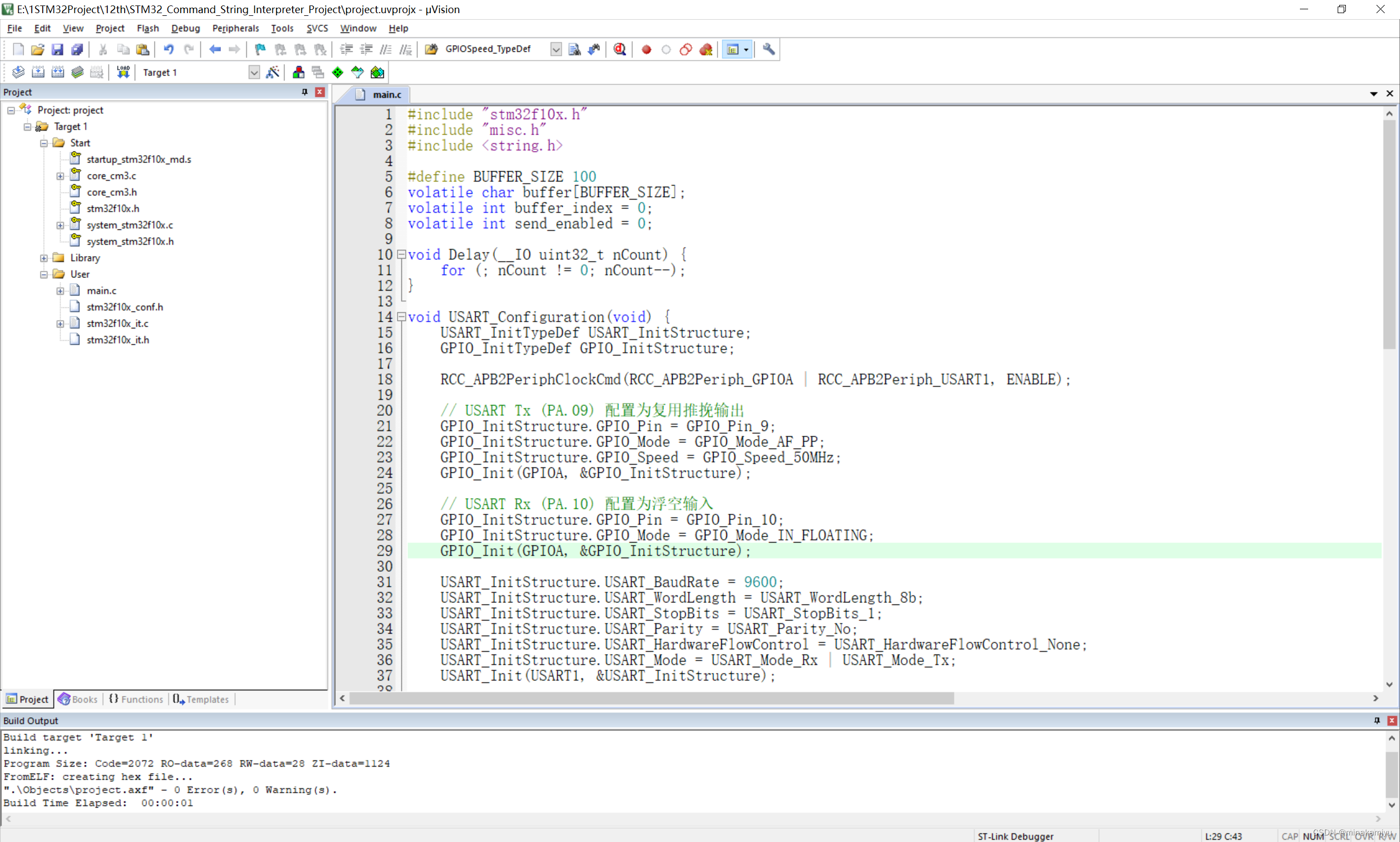
(二)当stm32接收到字符“stop stm32!”时,停止持续发送“hello windows!”;当接收到字符“go stm32!”时,持续发送“hello windows!”(提示:要将接收到的连续字符保存到一个字符数组里,进行判别匹配。写一个接收字符串的函数。)
1.代码和思路
#include "stm32f10x.h"
#include "misc.h"
#include <string.h>

#define BUFFER_SIZE 100
volatile char buffer[BUFFER_SIZE];
volatile int buffer_index = 0;
volatile int send_enabled = 0;

void Delay(__IO uint32_t nCount) {
    for (; nCount != 0; nCount--);
}

void USART_Configuration(void) {
    USART_InitTypeDef USART_InitStructure;
    GPIO_InitTypeDef GPIO_InitStructure;

    RCC_APB2PeriphClockCmd(RCC_APB2Periph_GPIOA | RCC_APB2Periph_USART1, ENABLE);

    // USART Tx (PA.09) 配置为复用推挽输出
    GPIO_InitStructure.GPIO_Pin = GPIO_Pin_9;
    GPIO_InitStructure.GPIO_Mode = GPIO_Mode_AF_PP;
    GPIO_InitStructure.GPIO_Speed = GPIO_Speed_50MHz;
    GPIO_Init(GPIOA, &GPIO_InitStructure);

    // USART Rx (PA.10) 配置为浮空输入
    GPIO_InitStructure.GPIO_Pin = GPIO_Pin_10;
    GPIO_InitStructure.GPIO_Mode = GPIO_Mode_IN_FLOATING;
    GPIO_Init(GPIOA, &GPIO_InitStructure);

    USART_InitStructure.USART_BaudRate = 9600;
    USART_InitStructure.USART_WordLength = USART_WordLength_8b;
    USART_InitStructure.USART_StopBits = USART_StopBits_1;
    USART_InitStructure.USART_Parity = USART_Parity_No;
    USART_InitStructure.USART_HardwareFlowControl = USART_HardwareFlowControl_None;
    USART_InitStructure.USART_Mode = USART_Mode_Rx | USART_Mode_Tx;
    USART_Init(USART1, &USART_InitStructure);

    USART_ITConfig(USART1, USART_IT_RXNE, ENABLE); // 开启接收中断
    USART_Cmd(USART1, ENABLE);
}

void NVIC_Configuration(void) {
    NVIC_InitTypeDef NVIC_InitStructure;

    NVIC_PriorityGroupConfig(NVIC_PriorityGroup_0);
    NVIC_InitStructure.NVIC_IRQChannel = USART1_IRQn;
    NVIC_InitStructure.NVIC_IRQChannelSubPriority = 0;
    NVIC_InitStructure.NVIC_IRQChannelPreemptionPriority = 0;
    NVIC_InitStructure.NVIC_IRQChannelCmd = ENABLE;
    NVIC_Init(&NVIC_InitStructure);
}

void USART1_IRQHandler(void) {
    if (USART_GetITStatus(USART1, USART_IT_RXNE) != RESET) {
        char data = (char)USART_ReceiveData(USART1);
        if (buffer_index < BUFFER_SIZE - 1) {
            buffer[buffer_index++] = data;
            buffer[buffer_index] = '\0';  // 保持字符串结尾

            char* temp_buffer = (char*)buffer; // 创建一个非 volatile 指针

            if (strstr(temp_buffer, "stop stm32!") != NULL) {
                send_enabled = 0;
                buffer_index = 0;  // 清空缓冲区
            } else if (strstr(temp_buffer, "go stm32!") != NULL) {
                send_enabled = 1;
                buffer_index = 0;  // 清空缓冲区
            }
        }
    }
}

int main(void) {
    SystemInit();
    USART_Configuration();
    NVIC_Configuration();

    char *str = "hello windows!\r\n";
    while (1) {
        if (send_enabled) {
            for (uint32_t i = 0; i < strlen(str); i++) {
                while (USART_GetFlagStatus(USART1, USART_FLAG_TXE) == RESET);
                USART_SendData(USART1, str[i]);
            }
        }
        Delay(5000000);
    }
}
思路:
- 系统初始化
首先是系统的基本初始化,包括系统时钟和串口配置。这一步是为了配置和启动基本的硬件设备,确保STM32可以正常工作并进行数据通信。 - USART配置
GPIO配置:配置GPIOA的9号脚(Tx发射端)为复用推挽输出,10号脚(Rx接收端)为浮空输入,以适应串口通信的物理连接需求。
USART设置:设置串口1的波特率、字长、停止位、奇偶校验位和流控,以及启用其接收和发送功能。 - 中断配置
使能USART接收中断:这允许设备在接收到数据时自动触发中断服务程序(ISR),处理接收到的数据。
NVIC配置:配置中断控制器,设置中断优先级和中断通道,确保USART中断可以被有效处理。 - 中断服务程序(ISR)
这里是处理接收数据的核心逻辑:
数据接收:从USART数据寄存器读取接收到的数据。
缓冲区管理:将接收到的数据逐字节存储到缓冲区,并在缓冲区末尾维护字符串结束符。
字符串匹配:检查缓冲区中是否包含特定控制命令(如"stop stm32!“或"go stm32!”),并根据匹配结果更新发送模式的使能状态。
控制逻辑:当接收到"stop stm32!"命令时,停止发送数据;接收到"go stm32!"命令时,开始或继续发送数据。 - 主循环
主循环中包含了数据发送的逻辑:
条件判断:根据send_enabled变量的状态决定是否发送数据。
数据发送:若允许发送数据,则循环发送预设的字符串"hello windows!\r\n"。
延时:在发送完一次数据后进行延迟,以便观察发送数据的效果。
2.运行效果和实验
12-2-2


 680
680

 被折叠的 条评论
为什么被折叠?
被折叠的 条评论
为什么被折叠?
 到【灌水乐园】发言


