


 本文详细解读IPv6组播地址的组成,包括8位固定前缀、标志字段(Rendezvous、Prefix和Transient)、范围标识和组ID。讲解了如何通过这些元素识别多设备群组,以及特殊地址如节点信息查询和 Solicited Node Multicast Address的应用。
 https://www.computernetworkingnotes.com/networking-tutorials/ipv6-multicast-addresses-explained.html
This tutorial explains the structures and functions of the IPv6 multicast addresses in detail. Learn what multicast addresses are and how they work in the IPv6 network.
A multicast group is the group of multiple nodes in the network. To identify group members, a common group ID is assigned to all group members. In IPv6 networks, this common group ID is known as the multicast address. In other words, a multicast address identifies a group of multiple devices in the network. Data packets sent on a multicast address are received by all group members.
IPv6 multicast addresses structure
The following image shows the structure of IPv6 multicast addresses.
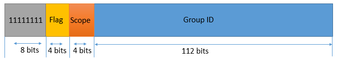
The first 8 bits of IPv6 multicast addresses are always set to 11111111. Therefore, in hexadecimal notation, an IPv6 multicast address always begins with FF. Beyond the first 8 bits, multicast addresses include additional structure to identify flags, their scope, and the multicast group.
Flags
The flags field starts after the first field (fix 8 bits). The size of this field is 4 bits. The 9th bit is set to 0. The next three bits are used to set three different types of flags. These flags are the R (Rendezvous) flag, P (Prefix) flag, and T (Transient) flag. To set these flags, 10Th, 11th, and 12th bits are used respectively.
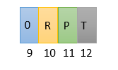
The R flag indicates whether the multicast address contains an embedded rendezvous point address. A multicast rendezvous point (RP) enables subscribers to link in the multicast group temporarily before joining the group permanently. If the value of this field is set to 1, it indicates that the multicast address is based on a unicast prefix, but the RP interface ID is also specified.
The P flag indicates whether the multicast address is based on a unicast address or not. If the value of this flag is set to 0, the multicast address is not assigned based on the unicast address. If the value of this flag is set to 1, the multicast address is based on the network prefix of the unicast subnet address.
The T bit indicates whether the multicast address is transient or is a well-known address assigned by IANA.
If the T flag is set to 0, it indicates that the multicast address is a well-known permanently assigned multicast address. These addresses are assigned by the IANA (Internet Assigned Numbers Authority).
If the T flag is set to 1, it indicates that the multicast address is transient. A transient multicast address is a multicast address that is not permanently assigned.
The following table summarizes the flag values.
| Flags (Binary) | Prefix | Description |
| 0000 | FF00::/12 | Permanently assigned 112-bit group ID scoped by 4-bit scope field |
| 0001 | FF10::/12 | Temporarily assigned 112-bit group ID scoped by 4-bit scope field |
| 0011 | FF30::/12 | Temporarily assigned unicast prefix-based multicast address |
| 0111 | FF70::/12 | Temporarily assigned unicast prefix-based multicast address with rendezvous point interface ID |
Scope
The size of the scope field is 4 bits. It starts after the flag field. It indicates the scope of the IPv6 network for which the multicast traffic is intended to be delivered. Routers use multicast scope field to determine whether multicast traffic can be forwarded or not.
| Value | Scope |
| 0 | Reserved |
| 1 | Interface-local scope |
| 2 | Link-local scope |
| 3 | Reserved |
| 4 | Admin-local scope |
| 5 | Site-local scope |
| 8 | Organization-local scope |
| E | Global scope |
| F | Reserved |
Except the values listed in the table above, all values are currently unassigned.
Group ID
The group ID field starts after the scope field. The size of this field is 112 bits. This field contains the value that is unique within the scope. This field provides a unique identity to the multicast group represented by the multicast address.
There are two types of group ID: Permanently assigned group IDs and Transient group IDs. Permanently assigned group IDs are independent of the scope. Transient group IDs are relevant only to a specific scope.
The following table lists the defined multicast addresses for all nodes and routers in all scopes.
| Multicast address | Scope | Devices |
| FF01::1 | Interface-local multicast address | All nodes |
| FF01::2 | Interface-local multicast address | All routers |
| FF02::1 | Link-local multicast address | All nodes (broadcast) |
| FF02::2 | Link-local multicast address | All nodes (multicast) |
| FF02::2 | Link-local multicast address | All routers |
| FF05::2 | Site-local multicast address | All routers |
IPv6 does not define any broadcast address. All IPv4 broadcast addresses are replaced by the link-local multicast address FF02::1. In other words, the addresses FF02::1 and FF02::2 are the equivalent of the broadcast and multicast addresses of the IPv4.
Special IPv6 multicast address
By default, all nodes on an IPv6 link support two special types of multicast addresses. These addresses are the node information query address and the solicited-node multicast address.
Node Information Query Address
Node information multicast query allows nodes to identify or resolve the IP address of a known hostname. It works similar to DNS service but only limited to the local network and can be used only for diagnostic and debugging purposes. In this mechanism, instead of querying a DNS server, a query is issued to the node information query address.
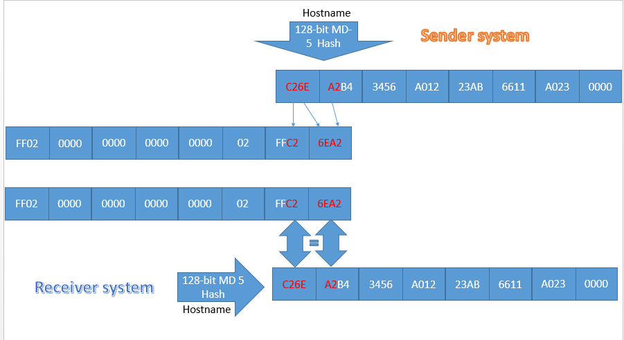
The node which wants to resolve the IP address of a known hostname calculates a hash of the hostname by using the 128-bit MD-5 algorithm. From the result, it takes the first 24 bits and appends them to the FF02::2:FF00:0/104 prefix to create a node information query address. After creating this address, the node sends a query message to this address.
When a node receives a message addressed to the information query address, it reverts the process. It creates a hash of its own hostname and compares the first 24 bits of the hash with the last 24 bits of the address of the received message. If it matches, the node replies with the requested information.
The following image shows how the node information query address works.
Solicited Node Multicast Address
Solicited node multicast address allows an IPv6 enabled device to find other IPv6 enabled devices on the link. It is used in the neighbor discovery protocol and duplicate address detection phase of the address autoconfiguration process.
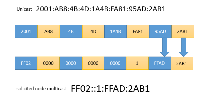
This address is formed by appending the low-order (rightmost) 24 bits of the solicited node’s interface ID to the well-known FF02::1:FF00/104 prefix. For example, suppose a node wishes to resolve the link-layer address of the device with IP address 2001:AB8:4B:4D:1:FA8:1A4B:95AD:2AB1. Using the lower order 24 bits, AD2AB1 in Hex, the device would address its request to the FF02::1:FFAD:2AB1.
The following image shows how a unicast address converts into the solicited-node multicast address.
That's all for this tutorial. If you like this tutorial, please share it with friends via your favorite social networking sites and subscribe to our YouTube channel.
By ComputerNetworkingNotes Updated on 2022-04-09 11:21:53 IST


 被折叠的 条评论
为什么被折叠?
被折叠的 条评论
为什么被折叠?
 到【灌水乐园】发言


