一、AT24C64电路图
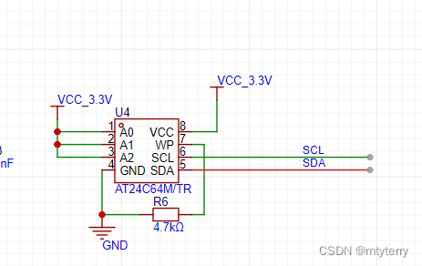
二、程序编码
1.定义I2C总线连接的GPIO端口
/* 定义I2C总线连接的GPIO端口, 用户只需要修改下面4行代码即可任意改变SCL和SDA的引脚 */

#define RCC_I2C_PORT     SysctrlPeripheralGpio        /* GPIO端口时钟 */

#define PORT_I2C_SCL    GpioPortA            /* GPIO端口 */
#define PIN_I2C_SCL        GpioPin8        /* GPIO引脚 */

#define PORT_I2C_SDA    GpioPortB            /* GPIO端口 */
#define PIN_I2C_SDA        GpioPin15        /* GPIO引脚 */

#define I2C_SCL_PIN        GpioPin8            /* 连接到SCL时钟线的GPIO */
#define I2C_SDA_PIN        GpioPin15            /* 连接到SDA数据线的GPIO */

/* 定义读写SCL和SDA的宏 */
#define I2C_SCL_1()  Gpio_WriteOutputIO(PORT_I2C_SCL, PIN_I2C_SCL, TRUE)                /* SCL = 1 */
#define I2C_SCL_0()  Gpio_WriteOutputIO(PORT_I2C_SCL, PIN_I2C_SCL, FALSE)                /* SCL = 0 */

#define I2C_SDA_1()  Gpio_WriteOutputIO(PORT_I2C_SDA, PIN_I2C_SDA, TRUE)                /* SDA = 1 */
#define I2C_SDA_0()  Gpio_WriteOutputIO(PORT_I2C_SDA, PIN_I2C_SDA, FALSE)                /* SDA = 0 */

#define I2C_SDA_READ()  (Gpio_GetInputIO(PORT_I2C_SDA,I2C_SDA_PIN) != 0)    /* 读SDA口线状态 */
#define I2C_SCL_READ()  (Gpio_GetInputIO(PORT_I2C_SCL,I2C_SCL_PIN) != 0)    /* 读SCL口线状态 */
2.HC32L130的GPIO模拟I2C总线程序
/*
*********************************************************************************************************
*	函 数 名: bsp_InitI2C
*	功能说明: 配置I2C总线的GPIO,采用模拟IO的方式实现
*	形    参:  无
*	返 回 值: 无
*********************************************************************************************************
*/

#define I2C_WR	0		/* 写控制bit */
#define I2C_RD	1		/* 读控制bit */
void App_InitI2C(void)
{
   InitSCLOutput();
   InitSDAOutput();

		/* 给一个停止信号, 复位I2C总线上的所有设备到待机模式 */
		i2c_Stop();
}
void InitSDAInput(void)
{
    stc_gpio_cfg_t         GpioInitStruct;
    DDL_ZERO_STRUCT(GpioInitStruct);

    //使能GPIO外设时钟
    Sysctrl_SetPeripheralGate(SysctrlPeripheralGpio, TRUE);
   	///< 端口方向配置->输入
    GpioInitStruct.enDir = GpioDirIn;
    ///< 端口驱动能力配置->高驱动能力
    GpioInitStruct.enDrv = GpioDrvL;
    ///< 端口上下拉配置->无上下拉
	  GpioInitStruct.enPu = GpioPuDisable; ///< 端口上下拉配置->无
    GpioInitStruct.enPd = GpioPdDisable;
    ///< 端口开漏输出配置->开漏输出关闭
   // GpioInitStruct.enOD = GpioOdEnable;
    ///< 端口输入/输出值寄存器总线控制模式配置->AHB
    GpioInitStruct.enCtrlMode = GpioAHB;
    Gpio_Init(PORT_I2C_SDA,PIN_I2C_SDA,&GpioInitStruct);               ///< 端口初始化

}
void InitSDAOutput(void)
{
		  stc_gpio_cfg_t         GpioInitStruct;
    DDL_ZERO_STRUCT(GpioInitStruct);

    //使能GPIO外设时钟
    Sysctrl_SetPeripheralGate(SysctrlPeripheralGpio, TRUE);
   	///< 端口方向配置->输入
    GpioInitStruct.enDir = GpioDirOut;
    ///< 端口驱动能力配置->高驱动能力
    GpioInitStruct.enDrv = GpioDrvH;
    ///< 端口上下拉配置->无上下拉
	  GpioInitStruct.enPu = GpioPuDisable; ///< 端口上下拉配置->无
    GpioInitStruct.enPd = GpioPdDisable;
    ///< 端口开漏输出配置->开漏输出关闭
    GpioInitStruct.enOD = GpioOdEnable;
    ///< 端口输入/输出值寄存器总线控制模式配置->AHB
    GpioInitStruct.enCtrlMode = GpioAHB;
    Gpio_Init(PORT_I2C_SDA, PIN_I2C_SDA, &GpioInitStruct);
	  Gpio_WriteOutputIO(PORT_I2C_SDA, PIN_I2C_SDA, TRUE);
}
void InitSCLOutput(void)
{
    stc_gpio_cfg_t         GpioInitStruct;
    DDL_ZERO_STRUCT(GpioInitStruct);

    //使能GPIO外设时钟
    Sysctrl_SetPeripheralGate(SysctrlPeripheralGpio, TRUE);
   	///< 端口方向配置->输入
    GpioInitStruct.enDir = GpioDirOut;///
    GpioInitStruct.enDrv = GpioDrvH;///< 端口驱动能力配置->高驱动能力
	  GpioInitStruct.enPu = GpioPuDisable; ///< 端口上下拉配置->无
    GpioInitStruct.enPd = GpioPdDisable;
    ///< 端口开漏输出配置->开漏输出关闭
    GpioInitStruct.enOD = GpioOdDisable;
    GpioInitStruct.enCtrlMode = GpioAHB;///< 端口输入/输出值寄存器总线控制模式配置->AHB


	  Gpio_Init(PORT_I2C_SCL, PIN_I2C_SCL, &GpioInitStruct);
	  Gpio_WriteOutputIO(PORT_I2C_SCL, PIN_I2C_SCL, TRUE);
}
/*
*********************************************************************************************************
*	函 数 名: i2c_Delay
*	功能说明: I2C总线位延迟,最快400KHz
*	形    参:  无
*	返 回 值: 无
*********************************************************************************************************
*/
static void i2c_Delay(void)
{
	uint8_t i;

	/*
		CPU主频168MHz时,在内部Flash运行, MDK工程不优化。用台式示波器观测波形。
		循环次数为5时,SCL频率 = 1.78MHz (读耗时: 92ms, 读写正常,但是用示波器探头碰上就读写失败。时序接近临界)
		循环次数为10时,SCL频率 = 1.1MHz (读耗时: 138ms, 读速度: 118724B/s)
		循环次数为30时,SCL频率 = 440KHz, SCL高电平时间1.0us,SCL低电平时间1.2us

		上拉电阻选择2.2K欧时,SCL上升沿时间约0.5us,如果选4.7K欧,则上升沿约1us

		实际应用选择400KHz左右的速率即可
	*/
	for (i = 0; i < 3; i++);
}
/*
*********************************************************************************************************
*	函 数 名: i2c_Start
*	功能说明: CPU发起I2C总线启动信号
*	形    参:  无
*	返 回 值: 无
*********************************************************************************************************
*/
void i2c_Start(void)
{
	/* 当SCL高电平时,SDA出现一个下跳沿表示I2C总线启动信号 */
	I2C_SDA_1();
	I2C_SCL_1();
	i2c_Delay();
	I2C_SDA_0();
	i2c_Delay();

	I2C_SCL_0();
	i2c_Delay();
}
/*
*********************************************************************************************************
*	函 数 名: i2c_Start
*	功能说明: CPU发起I2C总线停止信号
*	形    参:  无
*	返 回 值: 无
*********************************************************************************************************
*/
void i2c_Stop(void)
{
	/* 当SCL高电平时,SDA出现一个上跳沿表示I2C总线停止信号 */
	I2C_SDA_0();
	i2c_Delay();
	I2C_SCL_1();
	i2c_Delay();
	I2C_SDA_1();
	i2c_Delay();
}
/*
*********************************************************************************************************
*	函 数 名: i2c_SendByte
*	功能说明: CPU向I2C总线设备发送8bit数据
*	形    参:  _ucByte : 等待发送的字节
*	返 回 值: 无
*********************************************************************************************************
*/
void i2c_SendByte(uint8_t _ucByte)
{
	uint8_t i;

	/* 先发送字节的高位bit7 */
	for (i = 0; i < 8; i++)
	{
		if (_ucByte & 0x80)
		{
			I2C_SDA_1();
		}
		else
		{
			I2C_SDA_0();
		}
		i2c_Delay();
		I2C_SCL_1();
		i2c_Delay();
		I2C_SCL_0();
		if (i == 7)
		{
			 I2C_SDA_1(); // 释放总线
		}
		_ucByte <<= 1;	/* 左移一个bit */
		i2c_Delay();
	}
}
/*
*********************************************************************************************************
*	函 数 名: i2c_ReadByte
*	功能说明: CPU从I2C总线设备读取8bit数据
*	形    参:  无
*	返 回 值: 读到的数据
*********************************************************************************************************
*/
uint8_t i2c_ReadByte(void)
{
	uint8_t i;
	uint8_t value;

	/* 读到第1个bit为数据的bit7 */
	value = 0;
	for (i = 0; i < 8; i++)
	{
		value <<= 1;
		I2C_SCL_1();
		i2c_Delay();
		if (I2C_SDA_READ())
		{
			value++;
		}
		I2C_SCL_0();
		i2c_Delay();
	}
	return value;
}
/*
*********************************************************************************************************
*	函 数 名: i2c_WaitAck
*	功能说明: CPU产生一个时钟,并读取器件的ACK应答信号
*	形    参:  无
*	返 回 值: 返回0表示正确应答,1表示无器件响应
*********************************************************************************************************
*/
uint8_t i2c_WaitAck(void)
{
	uint8_t re;

	I2C_SDA_1();	/* CPU释放SDA总线 */
	i2c_Delay();
	I2C_SCL_1();	/* CPU驱动SCL = 1, 此时器件会返回ACK应答 */
	i2c_Delay();
	if (I2C_SDA_READ())	/* CPU读取SDA口线状态 */
	{
		re = 1;
	}
	else
	{
		re = 0;
	}
	I2C_SCL_0();
	i2c_Delay();
	return re;
}
/*
*********************************************************************************************************
*	函 数 名: i2c_Ack
*	功能说明: CPU产生一个ACK信号
*	形    参:  无
*	返 回 值: 无
*********************************************************************************************************
*/
void i2c_Ack(void)
{
	I2C_SDA_0();	/* CPU驱动SDA = 0 */
	i2c_Delay();
	I2C_SCL_1();	/* CPU产生1个时钟 */
	i2c_Delay();
	I2C_SCL_0();
	i2c_Delay();
	I2C_SDA_1();	/* CPU释放SDA总线 */
}
/*
*********************************************************************************************************
*	函 数 名: i2c_NAck
*	功能说明: CPU产生1个NACK信号
*	形    参:  无
*	返 回 值: 无
*********************************************************************************************************
*/
void i2c_NAck(void)
{
	I2C_SDA_1();	/* CPU驱动SDA = 1 */
	i2c_Delay();
	I2C_SCL_1();	/* CPU产生1个时钟 */
	i2c_Delay();
	I2C_SCL_0();
	i2c_Delay();
}
/*
*********************************************************************************************************
*	函 数 名: i2c_CheckDevice
*	功能说明: 检测I2C总线设备,CPU向发送设备地址,然后读取设备应答来判断该设备是否存在
*	形    参:  _Address:设备的I2C总线地址
*	返 回 值: 返回值 0 表示正确, 返回1表示未探测到
*********************************************************************************************************
*/
uint8_t i2c_CheckDevice(uint8_t _Address)
{
	uint8_t ucAck;
	if (I2C_SDA_READ() && I2C_SCL_READ())
	{
		i2c_Start();		/* 发送启动信号 */

		/* 发送设备地址+读写控制bit(0 = w, 1 = r) bit7 先传 */
		i2c_SendByte(_Address | I2C_WR);
		ucAck = i2c_WaitAck();	/* 检测设备的ACK应答 */
		i2c_Stop();			/* 发送停止信号 */

		return ucAck;
	}
	return 1;	/* I2C总线异常 */
}
3.AT24C64读写程序
include "app_at24c64.h"
#include "gpio.h"
#include "app_i2c_gpio.h"

void App_AT24C64Init(void){
  App_InitI2C();
}
/*
*********************************************************************************************************
*	函 数 名: ee_ReadBytes
*	功能说明: 从串行EEPROM指定地址处开始读取若干数据
*	形    参:  _usAddress : 起始地址
*			 _usSize : 数据长度,单位为字节
*			 _pReadBuf : 存放读到的数据的缓冲区指针
*	返 回 值: 0 表示失败,1表示成功
*********************************************************************************************************
*/
uint8_t App_x24c64_readbuff(uint8_t *_pReadBuf, uint16_t _usAddress, uint16_t _usSize)
{
	uint16_t i;
	i2c_Start();
	i2c_SendByte(EE_DEV_ADDR | I2C_WR);	/* 此处是写指令 */
  i2c_WaitAck();
	i2c_SendByte((uint8_t)(_usAddress >> 8));
	i2c_WaitAck();
	i2c_SendByte((uint8_t)(_usAddress& 0x00FF));
	i2c_WaitAck();
	i2c_Start();
	i2c_SendByte(EE_DEV_ADDR | I2C_RD);	/* 此处是读指令 */
  i2c_WaitAck();
	for (i = 0; i < _usSize; i++)
	{
		_pReadBuf[i] = i2c_ReadByte();
		if (i != _usSize - 1)
		{
			i2c_Ack();
		}
		else
		{
			i2c_NAck();
		}
	}
	i2c_Stop();
	return 0;
}
/*
*********************************************************************************************************
*	函 数 名: App_x24c64_writebuf
*	功能说明: 向串行EEPROM指定地址写入若干数据,采用页写操作提高写入效率
*	形    参:  _usAddress : 起始地址
*			 _usSize : 数据长度,单位为字节
*			 _pWriteBuf : 存放读到的数据的缓冲区指针
*	返 回 值: 0 表示失败,1表示成功
*********************************************************************************************************
*/
void App_x24c64_writebuf(uint8_t *_pWriteBuf, uint16_t _usAddress, uint16_t _usSize)
{
		uint16_t i;
	i2c_Start();
	i2c_SendByte(EE_DEV_ADDR | I2C_WR);	/* 此处是写指令 */
  i2c_WaitAck();
	i2c_SendByte((uint8_t)(_usAddress >> 8));
	i2c_WaitAck();
	i2c_SendByte((uint8_t)(_usAddress& 0x00FF));
	i2c_WaitAck();
	for(i=0;i<_usSize;i++){
	i2c_SendByte(_pWriteBuf[i]);
	i2c_WaitAck();
	}
	i2c_Stop();
}
void App_x24c64_writeOnePage(unsigned char *buffer,uint16_t addr,unsigned char len){
  unsigned char i=0;
  if(len>32)len=32;
	  App_x24c64_writebuf(buffer,addr,len);
     delay10us(500);
}
void App_x24c64_writebuff(uint8_t *buffer, uint16_t addr, int num)
{
      uint8_t NumOfPage = 0, NumOfSingle = 0, Addr = 0, count = 0, temp = 0;
  Addr = addr % 32;/*不满一页的开始写的地址*/
  count = 32 - Addr;/*不满一页的地址剩余容量*/
  NumOfPage =  num / 32;/*写了完整的页数*/
  NumOfSingle = num % 32;/*写完完整页剩余的容量*/

    /* 写进的地址是在页的首地址  */
  if(Addr == 0){
    /*写进的字节数不足一页*/
    if(NumOfPage == 0)
      App_x24c64_writeOnePage(buffer, addr, NumOfSingle);
    /*写进的字节数大于一页*/
    else{
      while(NumOfPage--){
            //    printf("NumOfPage=%d\r\n",NumOfPage);
        App_x24c64_writeOnePage(buffer, addr, 32 ); /*写一页*/
        addr +=  32 ;
        buffer+= 32 ;
      }/*写完整页*/
        //    printf("NumOfSingle=%d\r\n",NumOfSingle);
      if(NumOfSingle!=0){/*写尾数*/
        App_x24c64_writeOnePage(buffer, addr, NumOfSingle);

      }
    }
  } /* 假如写进的地址不在页的首地址*/
  else {

    if (NumOfPage == 0) {/*写进的字节数不足一页 */

      if (NumOfSingle > count){
       /*要写完完整页剩余的容量大于不满一页的地址剩余容量*/
        temp = NumOfSingle - count;
        App_x24c64_writeOnePage(buffer, addr, count);/*把当前页的地址写完*/
        addr +=  count;
        buffer += count;
        App_x24c64_writeOnePage(buffer, addr, temp);/*在新的一页写剩余的字节*/
      }
      else
      {
        App_x24c64_writeOnePage(buffer, addr, num);
      }
    }
    else{ /*写进的字节数大于一页*/

      num -= count;
      NumOfPage =  num / 32;
      NumOfSingle = num % 32;

      App_x24c64_writeOnePage(buffer, addr, count);/*把当前页的地址写完*/
      addr +=  count;
      buffer += count;

      while (NumOfPage--)
      {
        App_x24c64_writeOnePage(buffer, addr, 32);
        addr +=  32;
        buffer += 32;
      }

      if (NumOfSingle != 0)
      {
        App_x24c64_writeOnePage(buffer, addr, NumOfSingle);
      }
    }
  }

}
4.测试程序
#include <stdio.h>
#include <stdint.h>
#include "app_RS485.h"
#include "app_at24c64.h"
#include "app_i2c_gpio.h"
void App_x24c64_test();
/**
******************************************************************************
** \brief Main function of project
**
** \return uint32_t return value, if needed
**
** This sample
**
******************************************************************************/
unsigned char level_f[8]={0x01,0x03,0x00,0x02,0x00,0x02,0x65,0xCB};//测量值浮点型输出
extern uint8_t u8RxCnt;
extern uint8_t level_fv[10];
int32_t main(void)
{
App_AT24C64Init();
App_RS485Init(9600);
// app_RS485Sendbuff(level_f,8);
App_x24c64_test();
while(1)
{
delay1ms(100);
if(g_RS485.RxFlag==1){
app_RS485Sendbuff(g_RS485.Rxbuff,g_RS485.RxCnt);
}
}
}
void App_x24c64_test(){
uint8_t u8Senddata[33] = {0x01,0x02,0x03,0x04,0x05,0x06,0x07,0x08,0x09,0x10,0x11,0x12,0x13,0x14,0x15,0x16,0x17,0x18,0x19,0x20,0x21,0x22,0x23,0x24,0x25,0x26,0x27,0x28,0x29,0x30,0x31,0x32,0x33};
uint8_t u8Recdata[33]={0x00};
int32_t temp;
uint8_t i=0;
App_x24c64_writebuff(u8Senddata,0,33);
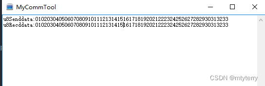
printf("u8Senddata:");
for(temp=0;temp<33;temp++){
printf("%02X",u8Senddata[temp]);
}
delay1ms(100);
App_x24c64_readbuff(u8Recdata,0,33);
printf("\r\nu8Recddata:");
for(temp=0;temp<33;temp++){
printf("%02X",u8Recdata[temp]);
}
}
5.测试结果


 2494
2494

 被折叠的 条评论
为什么被折叠?
被折叠的 条评论
为什么被折叠?
 到【灌水乐园】发言


