


此文来源:
https://www.visual-paradigm.com/features/uml-tool/
1、UML的种类

2、每种种类的例子
2.1 用例图:
Use Case Diagram
Capture functional requirements with UML use case diagram tool. Each use case in a use case diagram represents a high level business goal that yields a measurable result of business values. (UML) Actors are connected with use cases to represent the roles that interact with the functions.
用UML用例图 建立功能性需求。在用例图中的每个用例通过可度量的业务结果来实现高水平业务目标。参与者用用例来表示函数中角色与功能的相互作用。

2.2 Class Diagram 类图
Model the structure of system by modeling its classes, their attributes and operations in a UML class diagram. UML class diagram is a blueprint of the classes(code level) required to build a software system. Programmers implement a software system with the help of both the class diagram and the class specification.
UML类图 用来模拟系统结构中的类,包括 类的 属性、方法 。

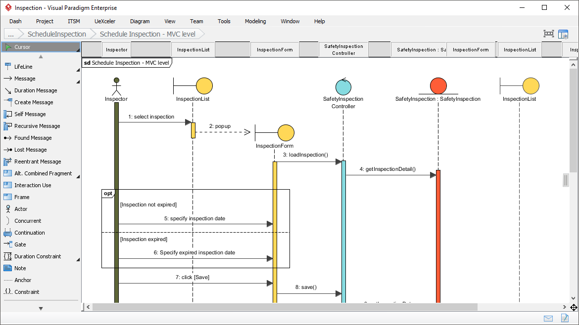
2.3、Sequence Diagram 序列图
Visualize the interactions between users, systems and sub-systems over time through message passing between objects or roles. If class diagram represents the skeleton of classes by showing their attributes and methods, UML sequence diagram complete the classes by representing the programming logic to be filled in methods' body.
通过对象或角色之间的消息传递,可视化用户、系统和子系统之间的相互作用。如果类图通过显示类的属性和方法来表示类的骨架,那么UML序列图通过表示要填充在方法体中的编程逻辑来完成类。
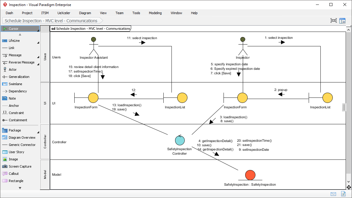
2.4、Communication Diagram 交互图
Collaboration between objects in runtime can be modeled in the UML tool, with a UML communication diagram. In a communication diagram, objects, called lifelines, are connected to represent the need of communication during the execution of an interaction. Messages can be added on top of the connectors to list the calls made from and to those lifelines.
2.5 Activity Diagram 行为图
Use UML activity diagram, a flowchart-based diagram to model the flow of control. Partition actions according to the type of participant involved.

2.6 State Machine Diagram 状态图
State machine diagram is a critical design model for event-driven systems. Well-designed state machine shows accurately the essential states of objects as well as the triggers of state change, which facilitates the development of error-free state machine.

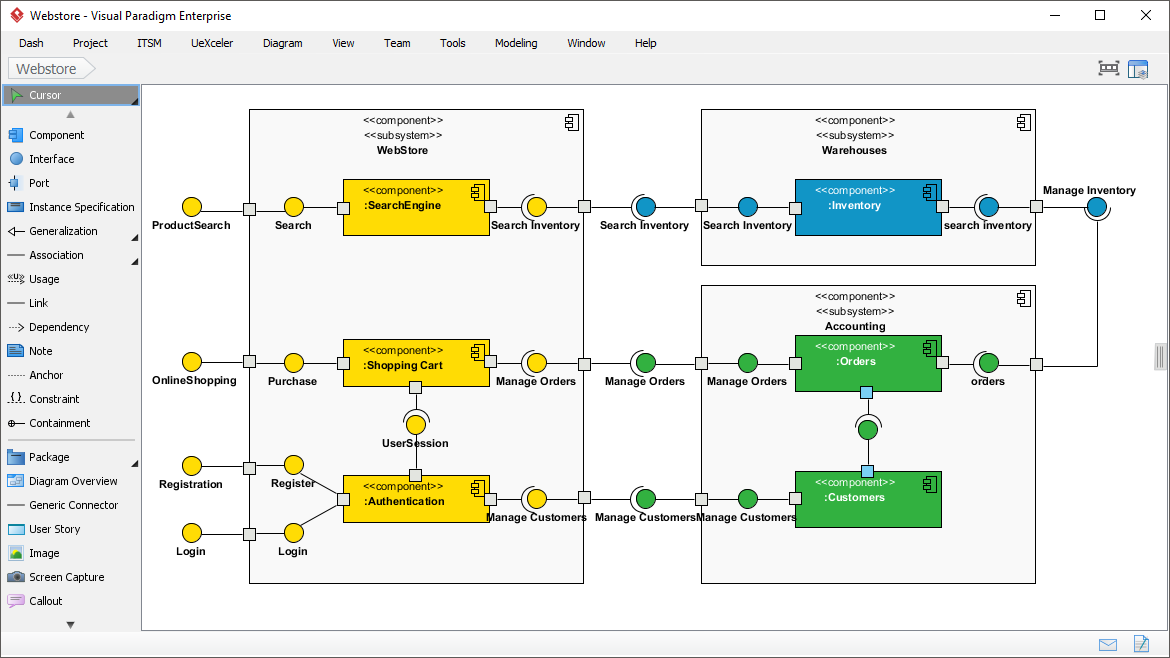
2.7 Component Diagram 组件图
Components diagrams are used to model the structure of systems by showing how little parts of the system gear up in forming a bigger part, or forming the entire software systems.
2.9 部署图 Deployment Diagram
Models the physical deployment of software components with UML deployment diagram. In deployment diagram, hardware components (e.g. web server, mail server, application server) are presented as nodes, with the software components that run inside the hardware components presented as artifacts.

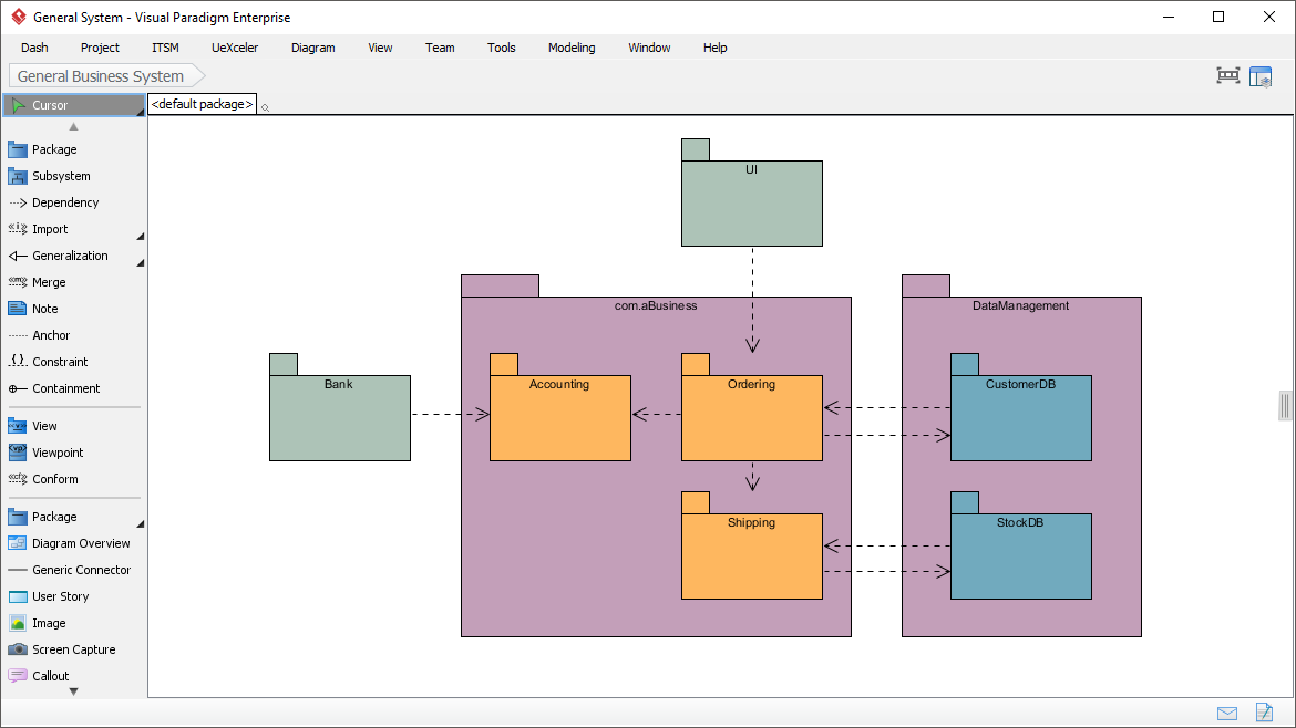
2.10 文件结构图 Package Diagram
Arrange and organize model for large-scale project with package diagrams. Package diagram is also good in visualizing structure and dependency between sub-systems or modules.
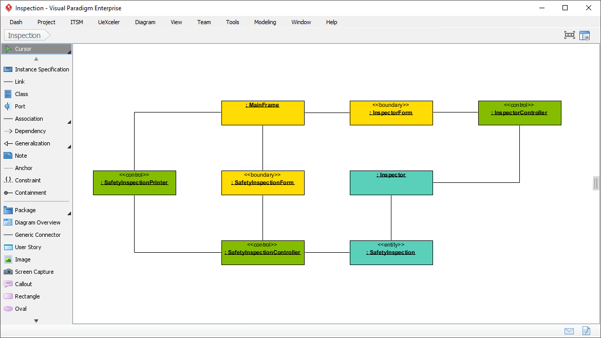
2.11 对象图 Object Diagram
View a snapshot of instances of classifiers in UML class diagrams. Similar to class diagrams, object diagrams show the static design of a system from a prototypical perspective.
查看UML类图中的分类器实例实例的快照。与类图相似,对象图从一个原型的角度展示了系统的静态设计
2.12 Composite Structure Diagram 复合结构图
Visualize the internal structure of a class or collaboration with UML composite structure diagram. Model a system from a micro point-of-view using UML composite structure diagram.
用UML复合结构图可视化类或协作的内部结构。利用UML复合结构图,从微观角度对系统进行建模。

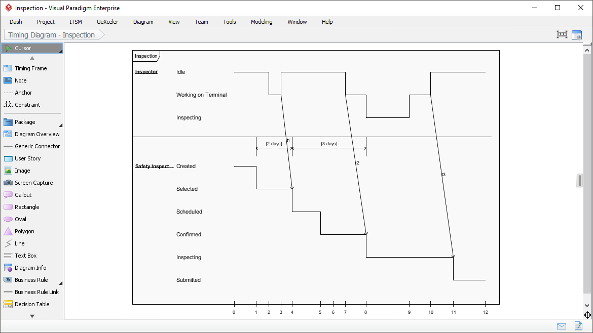
2.13 Timing Diagram
Timing diagrams model the behavior of objects throughout a given period of time. It is a commonly used UML tool for designing real-time and distributed systems. Just drag to move a time unit back and forth. Have a timing frame updated automatically according to your change.
时间图在给定的时间段内模拟对象的行为。它是一种常用的用于设计实时和分布式系统的UML工具。只需拖动一个时间单位来回移动。根据您的更改自动更新定时帧
Interaction Overview Diagram
View the sequence of interactions with UML interaction overview diagram. Interaction overview diagram helps represent complex scenario that involve multiple interactions presented as multiple UML sequence diagrams.


 952
952

 被折叠的 条评论
为什么被折叠?
被折叠的 条评论
为什么被折叠?
 到【灌水乐园】发言


