


现象
造成坏点的原因
1)感光元件芯片自身工艺技术瑕疵造成;
2)光纤采集存在缺陷;
3)制造商产品差异;
坏点分类
1)hot pixel:固定保持较高的像素值,一般呈现为画面高亮的点;
2)dead pixel:固定保持较低的像素值,一般在画面中呈现为暗点;
3)noise pixel:信号强度随光照呈现的变化规律不符合正常的变化规律;
校正方法
1)静态矫正:通常由sensor厂商在生产后进行标定,把所有坏点的坐标位置记录下来,然后矫正的时候直接通过查表得方式找到坏点进行矫正。
动态矫正:就是在ISP算法中通过特殊得算法判断一个点是否为坏点,如果是坏点就行行矫正,否则原样输出;
动态算法
因为静态坏点存在局限性,一方面是这种标定方式需要消耗人力物力,而且存储这些数据对硬件也有一定的要求;另一方面随着产品使用时间的增加,坏点的数目会增加,而产商的数据无法标定这些新增的坏点;还有另一方面是有些坏点表现为正常情况下的光电特性正常,只是在长时间使用或者高ISO的情况下才会变为坏点,这部分坏点正常使用时不用当作坏点处理,毕竟插值的数据和真实的数据还是由一定的差异。基于以上几点,静态坏点检测方法不进行讨论,而且实际应用的时候很多静态坏点检测也是disable。
PINTO算法
主要思想是坏点往往是在一个领域中的极亮或极暗点,所以以一个55的领域为检测区域。
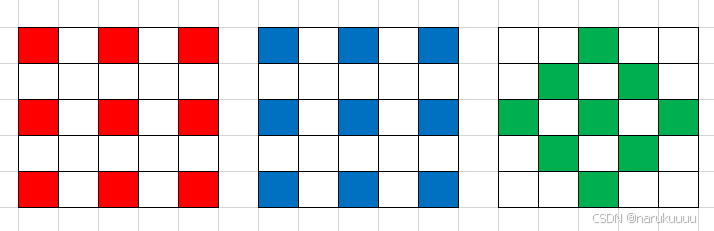
如图所示55的领域内同一颜色通道 相对于 中心像素都有8个临近像素。那么矫正按以下步骤操作:
1)计算中心像素与周围八个像素值的差;
2)判断八个差值是否都为正值或者都为负值;
3)如果有的为正,有的为负,那么就为正常值,否则进行下一步;
4)设置一个阈值,如果八个差值的绝对值都差过阈值,那么就判断为坏点;
5)判断为坏点后就用八个临近的像素值的中位值来替换当前的像素值;
梯度法

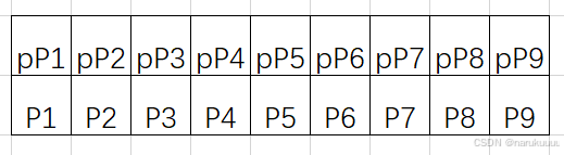
该算法的作者针对三个通道都使用这一种窗口进行检测,具体步骤如下:
1)计算四个方向的梯度:
水平方向三个二阶梯度:Dh1 = |P1+P3-2P2|, Dh2 = |P4+P5-2Pc|,Dh3 = |P6+P8-2P7|;
竖直方向三个二阶梯度:Dv1 = |P1+P6-2P4|, Dv2 = |P2+P7-2Pc|,Dv3 = |P3+P8-2P5|;
45°方向的三个二阶梯度:D45_1 = 2*|P4-P2|, D45_2 =|P3+P6-2Pc|, D45_3 = 2|P7-P5|;
135°三个二阶梯度:D135_1 = 2*|P2-P5|, D135_2 =|P1+P8-2Pc|, D135_3 = 2|P7-P4|;
2)取出各个方向梯度的绝对值的终值median_Dh = median(Dh1,Dh2,Dh3),同理取出三个方向的中值;
3)求出四个中值的最小值作为边缘方向,min_grad = min(median_Dh,median_Dv,median_D45,median_D135);
4)如果最小梯度方向为水平或者竖直,若过Pc那个梯度的绝对值大于同方向的另外两个梯度绝对值和的4倍,则Pc为坏点。
5)如果是45°方向,则计算135°三个梯度绝对值两两之差的绝对值的和

如果D135_sum小于100,若此时D45_2>3*(D45_1+D45_3)且D135_2>3*(D135_1+D135_3),则Pc为坏点。否则(D135_sum>100)D45_2>3*(D45_1+D45_3)就为坏点。
6)135°方向和45°相反的方向计算和判断即可。
7)为减少漏判,当Pc小于15且周围点都大于Pc40以上,则Pc为坏点。如果Pc大于230,且周围的点都小于Pc30以下,则该点为坏点;
8)边缘为水平方向,且判断为坏点,如过|P4-Pc|<|Pc-P5|则Pc更靠近P4,根据同一颜色通道亮度的渐变性可以推导出ouput=P4+(P2+P7-P1-P6)/2;否则ouput=P6+(P2+P7-P3-P8)/2;
9)如果为竖直方向可以参考水平方向求出;
10)边缘为45°,如果|P3-Pc|<|P6-Pc|则根据同一原则output=P3+(P4+P7-P2-p5)/2;否则为output=P6+(P2+P5-P7-P3)/2;
11)边缘为135°则按照45°的方式反过来计算即可。
DPC和demosaic结合法
这种方法就是将DPC算法和去马赛克的算法融合到一块,大体的思路就是在先对Bayer图像插值成全彩图像,然后对每个点进行坏点检测,检测的时候只用同一通道的像素检测,而且每个像素点用的颜色通道即为该点raw图对应的颜色通道,换句话说就是RGGB图像,对于这四个点,第一个点只通过周围插值出的R来检测R是否为坏点,其他两个同样这么处理,这样就保证和raw处理的时候一样,只用处理MxN个像素点就行,然后如果该点是坏点就对其进行矫正并重新对齐(取中位值)进行颜色插值,那么执行完这整个流程,坏点被矫正了而且直接输出了全彩图。
行检测法
这类算法检测和矫正的时候并不使用整帧图像,而是通过几行数据来处理,这样对硬件的buffer要求就没那么高。具体操作如下:
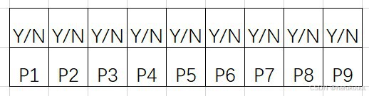
1)缓存一行数据,在同一行中通过比较同一通道相邻的数据的差值,如果待检测的点同时大于相邻点一个阈值,或者同时小于相邻点一个阈值,那么这个点就是候选坏点;
2)有的算法还会利用buffer缓存上一行的数据,然后判断这个点在当前行
周围有没有候选坏点,并判断上一行对应位置的点是否是为候选坏点,如果都不是,那么当前点就是真是坏点,就通过周围点矫正,如果周围有候选坏点,那么就判断为非真是坏点,不用矫正;
3)在上一条提到的缓存的上一行数据,有的算法中不是缓存上一行每个像素的信息,而是上一行经过处理判断后的属性值,比如上一行存储的是每个点是否为候选坏点或坏点,那么每个点就可以用0或者1来表示,那么上一行每个像素只需要1bit的数据来存储,这样就能进一步降低对硬件的要求。
具体实现
pinto算法:
clc;clear;close all;
tic;
% --------global velue---------
expandNum = 2;%扩展原图像
Th = 30;

% --------raw parameters-------
filePath = 'images/HisiRAW_4208x3120_8bits_RGGB.raw';
bayerFormat = 'RGGB';
bayerBits = 8;
row = 4208;
col = 3120;
% -----------------------------

rawData = readRaw(filePath, bayerBits, row, col);
[height, width, channel] = size(rawData);

img_expand = expandRaw(rawData, expandNum);

disImg = zeros(height, width);
for i = expandNum+1 : 2 : height+expandNum
    for j = expandNum+1 : 2 : width+expandNum
        % R
        % get the pixel around the current R pixel
        around_R_pixel = [img_expand(i-2, j-2) img_expand(i-2, j) img_expand(i-2, j+2) img_expand(i, j-2) img_expand(i, j+2) img_expand(i+2, j-2) img_expand(i+2, j) img_expand(i+2, j+2)];
        disImg(i-expandNum, j-expandNum)= judgeDefectPixel(around_R_pixel, img_expand(i, j), Th);
        %disImg是矫正后的新图,img_expand在原图像扩展边缘以确保 原图边缘的像素点 能够形成5*5进行矫正
        % Gr
        % get the pixel around the current Gr pixel
        around_Gr_pixel = [img_expand(i-1, j) img_expand(i-2, j+1) img_expand(i-1, j+2)  img_expand(i, j-1) img_expand(i, j+3) img_expand(i+1, j) img_expand(i+2, j+1) img_expand(i+1, j+2)];
        disImg(i-expandNum, j-expandNum+1) = judgeDefectPixel(around_Gr_pixel, img_expand(i, j+1), Th);
        % B
        % get the pixel around the current B pixel
        around_B_pixel = [img_expand(i-1, j-1) img_expand(i-1, j+1) img_expand(i-1, j+3) img_expand(i+1, j-1) img_expand(i+1, j+3) img_expand(i+3, j-1) img_expand(i+3, j+1) img_expand(i+3, j+3)];
        disImg(i-expandNum+1, j-expandNum+1) = judgeDefectPixel(around_B_pixel, img_expand(i+1, j+1), Th);
        % Gb
        % get the pixel around the current Gb pixel
        around_Gb_pixel = [img_expand(i, j-1) img_expand(i-1, j) img_expand(i, j+1) img_expand(i+1, j-2) img_expand(i+1, j+2) img_expand(i+2, j-1) img_expand(i+3, j) img_expand(i+2, j+1)];
        disImg(i-expandNum+1, j-expandNum) = judgeDefectPixel(around_Gb_pixel, img_expand(i+1, j), Th);
    end
end
figure();
imshow(rawData);title('org');
figure();
imshow(uint8(disImg));title('corrected');
disp(['cost time:',num2str(toc)])
判断是否为坏点
function correctP = judgeDefectPixel(aroundP, currentP, Th)
% judgeDefectPixel.m    correct the curren pixel
%   Input:
%       aroundP    	the pixel around the current pixel
%       currentP    the value of current pixel
%       Th          the threshold of the defect pixel
%   Output:
%       correctP    the corrected value of the pixel
% Last Modified by wtzhu v1.0 2021-07-16
% Note:
    % get the median value of the around list
    medianV = median(aroundP);
    % get the difference between the around pixel and the current pixel
    diff = aroundP - ones(1, numel(aroundP)) * currentP;
    % if all difference bigger than 0 or all smaller than 0 and all abs of the diff are bigger than Th, that pixel is
    % a defect pixel and replace it with the median;
    if (nnz(diff > 0) ==  numel(aroundP)) || (nnz(diff < 0) ==  numel(aroundP))
        if length(find((abs(diff)>Th)==1)) == numel(aroundP)
            correctP = medianV;
        else
            correctP = currentP;
        end
    else
        correctP = currentP;
    end
end
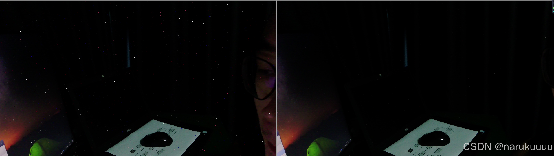
效果图:
转载来源:
https://blog.csdn.net/wtzhu_13/article/details/119077642?spm=1001.2014.3001.5502
https://www.bilibili.com/video/BV1dP4y1s7Rt/?spm_id_from=333.1387.homepage.video_card.click&vd_source=917b39787b71f9af867492b65b1fdec3


 843
843

 被折叠的 条评论
为什么被折叠?
被折叠的 条评论
为什么被折叠?
 到【灌水乐园】发言


