


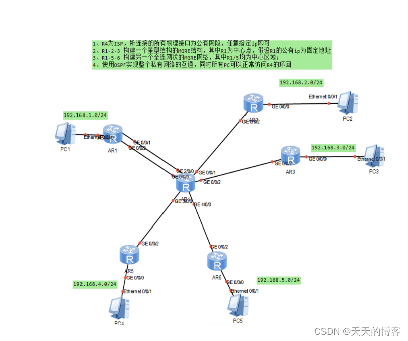
实验条件以及拓扑图:
1.配置pc以及路由器IP :
2.配置缺省路由:
[R1]ip route-static 0.0.0.0 0 61.1.1.6
[R1]ip route-static 0.0.0.0 0 16.1.1.6
[R2]ip route-static 0.0.0.0 0 26.1.1.6
[R3]ip route-static 0.0.0.0 0 36.1.1.6
[R5]ip route-static 0.0.0.0 0 46.1.1.6
[R6]ip route-static 0.0.0.0 0 56.1.1.6
3.配置NAT:
[R1]acl 2000
[R1-acl-basic-2000]rule 1 permit source any
[R1-acl-basic-2000]q
[R1]inter G4/0/1
[R1-GigabitEthernet0/0/1]nat outbound 2000(其余同理配置)
4.R1-R2-R3设置MGRE结构:
R1:
[R1]interface Tunnel 0/0/0
[R1-Tunnel0/0/0]ip add 10.1.1.1 24
[R1-Tunnel0/0/0]tunnel-protocol gre p2mp
[R1-Tunnel0/0/0]source 16.1.1.1
[R1-Tunnel0/0/0]nhrp entry multicast dynamic
[R1-Tunnel0/0/0]nhrp network-id 100
R2:
[R2]interface Tunnel 0/0/0
[R2-Tunnel0/0/0]ip address 10.1.1.2 24
[R2-Tunnel0/0/0]tunnel-protocol gre p2mp
[R2-Tunnel0/0/0]nhrp entry 10.1.1.1 16.1.1.1 register
[R2-Tunnel0/0/0]nhrp network-id 100
R3:
[R3]interface Tunnel 0/0/0
[R3-Tunnel0/0/0]ip address 10.1.1.3 24
[R3-Tunnel0/0/0]tunnel-protocol gre p2mp
[R3-Tunnel0/0/0]nhrp network-id 100
[R3-Tunnel0/0/0]nhrp entry 10.1.1.1 16.1.1.1 register
R1-R5-R6设置全网MGRE网络:
[R1-Tunnel0/0/1]ip add 20.1.1.1 24
[R1-Tunnel0/0/1]tunnel-protocol gre p2mp
[R1-Tunnel0/0/1]source 31.1.1.1
[R1-Tunnel0/0/1]nhrp entry multicast d
[R1-Tunnel0/0/1]nhrp network-id 200
[R1-Tunnel0/0/1]nhrp entry 20.1.1.5 56.1.1.4(R5,R6相同)
最后开启ospf协议,宣告对应网段


 54
54


 被折叠的 条评论
为什么被折叠?
被折叠的 条评论
为什么被折叠?
 到【灌水乐园】发言


