


Miracast流程分析
会话创建连接大体流程
-
WIFI-DIRECT (以前叫WIFI P2P),可以让WIFI设备不经过AP端连接,直接与另一台WIFI设备连线
-
如果source与sink为第一个连接,会进入GO协商(Group owner negotiation),经过req,response,confirm后,确定由source还是sink来作为group owner;否则直接建立连接进入RTSP协议传输
-
在WIFI-P2P建立好Source与sink端的TCP连接后,采用RTSP协议对流媒体进行控制,这里不会传输流数据,仅仅试媒体会话的控制和参数协商,比如分辨率,编码格式等
-
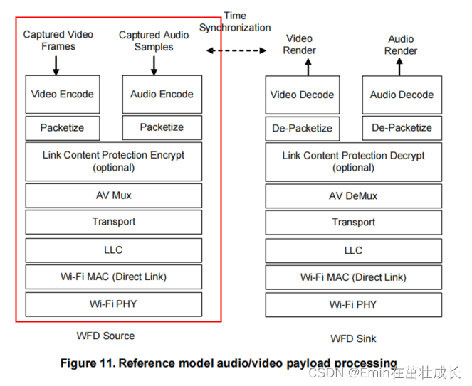
source端采集屏幕数据和音频数据,采用MediaCodec接口来送数据到编码器进行编码
-
将编码后的数据,打包为TS流,封装为网络RTP数据包,开始传输音视频流媒体数据
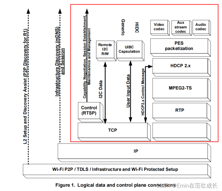
在多媒体相关播放控制模块,我们重点关注建立了P2P连接后的流程,即RTSP,源端数据采集以及编码,MPEG-TS打包以及RTP发送过程。(其中其实还涉及到HDCP的过程,本文暂时不深入分析)
RTSP过程
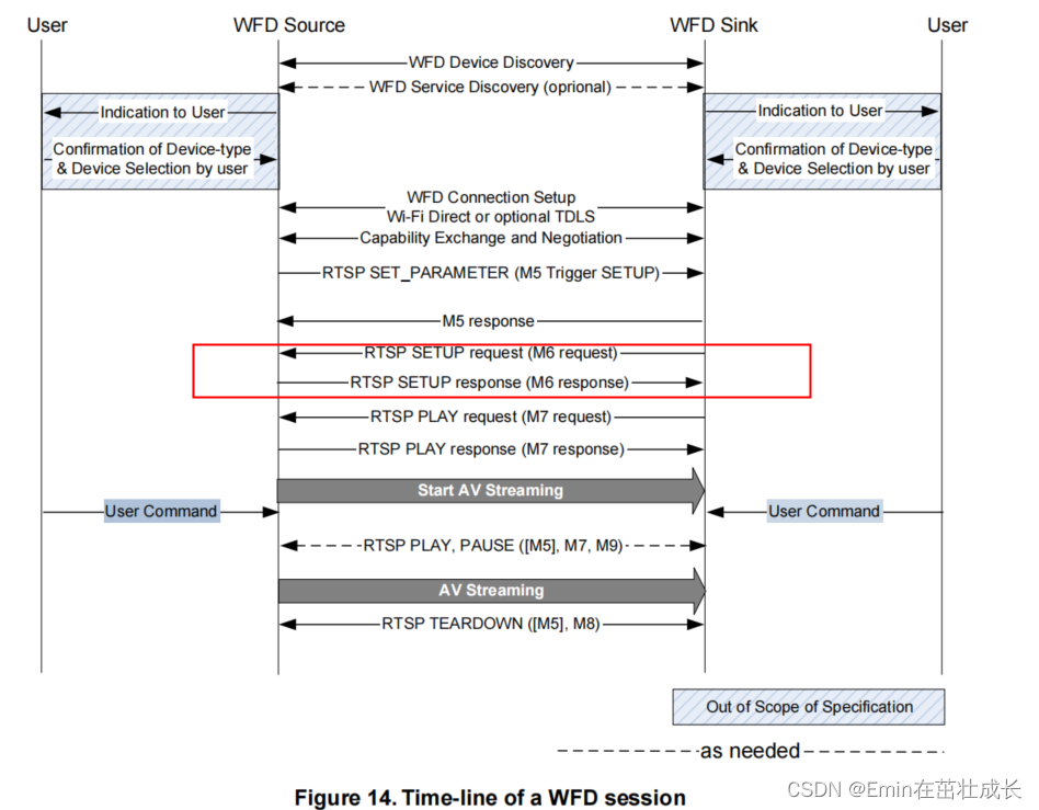
M1-M4阶段,RTSP的整体流程如下:
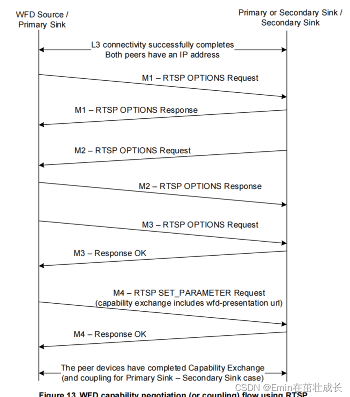
上面是WifiDisplay spec里面的流程图,具体到mircast source端的源码,我们来一步步分析整个RTSP的协商过程:
SendM1
ANetworkSession::Session::Session {
    sp<AMessage> msg = mNotify->dup();
    msg->setInt32("sessionID", mSessionID);
    msg->setInt32("reason", kWhatClientConnected);
    msg->setString("server-ip", localAddrString.c_str());
    msg->setInt32("server-port", ntohs(localAddr.sin_port));
    msg->setString("client-ip", remoteAddrString.c_str());
    msg->setInt32("client-port", ntohs(remoteAddr.sin_port));
    msg->post();
}
WifiDisplaySource消息队列的处理回调函数中,处理连接创建的消息kWhatClientConnected:
void WifiDisplaySource::onMessageReceived(const sp<AMessage> &msg) {
 case ANetworkSession::kWhatClientConnected:
        status_t err = sendM1(sessionID);
        CHECK_EQ(err, (status_t)OK);
    break;
}
发送完M1后,注册sink端的M1回应数据接收回调
 registerResponseHandler(
            sessionID, mNextCSeq, &WifiDisplaySource::onReceiveM1Response);
紧接着由sink端发送M2,source端发送M2的response,这里不分析,到了接下来试比较重要的协商阶段,会由Source端发送M3,请求sink端的参数,包括如下参数:
wfd_video_formats //视频格式参数
wfd_content_protection //内容版权保护相关
wfd_audio_codecs //音频编解码格式
wfd_client_rtp_ports //rtp端口号
通过sendM3方法,也可以看到参数请求的body里面,有这些参数集列表:
status_t WifiDisplaySource::sendM3(int32_t sessionID) {
    AString body =
        "wfd_content_protection\r\n"
        "wfd_video_formats\r\n"
        "wfd_audio_codecs\r\n"
        "wfd_client_rtp_ports\r\n";

    AString request = "GET_PARAMETER rtsp://localhost/wfd1.0 RTSP/1.0\r\n";
    AppendCommonResponse(&request, mNextCSeq);

    request.append("Content-Type: text/parameters\r\n");
    request.append(AStringPrintf("Content-Length: %d\r\n", body.size()));
    request.append("\r\n");
    request.append(body);

    status_t err =
        mNetSession->sendRequest(sessionID, request.c_str(), request.size());

    if (err != OK) {
        return err;
    }
此时sink端会发送M3阶段GET_PARAMETER的回应,将自己能提供的参数能力发送给source端。source端会解析sink端参数,从而进行最优参数的选择,为M4设置参数做准备,这个流程在onReceiveM3Response中进行
status_t WifiDisplaySource::onReceiveM3Response(int32_t sessionID, const sp<ParsedMessage> &msg) {
    //1.获取RTP端口号
    AString value;
    if (!params->findParameter("wfd_client_rtp_ports", &value)) {
        ALOGE("Sink doesn't report its choice of wfd_client_rtp_ports.");
        return ERROR_MALFORMED;
    }

    unsigned port0 = 0, port1 = 0;
    //这里判断是走UDP还是走TCP进行传输
    if (sscanf(value.c_str(),
               "RTP/AVP/UDP;unicast %u %u mode=play",
               &port0,
               &port1) == 2
        || sscanf(value.c_str(),
               "RTP/AVP/TCP;unicast %u %u mode=play",
               &port0,
               &port1) == 2) {
            if (port0 == 0 || port0 > 65535 || port1 != 0) {
                ALOGE("Sink chose its wfd_client_rtp_ports poorly (%s)",
                      value.c_str());

                return ERROR_MALFORMED;
            }
    } else if (strcmp(value.c_str(), "RTP/AVP/TCP;interleaved mode=play")) {
        ALOGE("Unsupported value for wfd_client_rtp_ports (%s)",
              value.c_str());

        return ERROR_UNSUPPORTED;
    }

    //2.获取video格式参数
    if (!params->findParameter("wfd_video_formats", &value)) {
        ALOGE("Sink doesn't report its choice of wfd_video_formats.");
        return ERROR_MALFORMED;
    }
    //如果读到的wfd_video_formats不为none,则会进行解析
    if  (!(value == "none")) {
        mSinkSupportsVideo = true;

        //这一步是比较重要的对sink的videoformats成员进行解析和设置,后面会进行分析
        if (!mSupportedSinkVideoFormats.parseFormatSpec(value.c_str())) {
            ALOGE("Failed to parse sink provided wfd_video_formats (%s)",
                  value.c_str());
            return ERROR_MALFORMED;
        }
        //根据mSupportedSinkVideoFormats和mSupportedSinkVideoFormats这两个参数集,选择最优参数
        if (!VideoFormats::PickBestFormat(
                    mSupportedSinkVideoFormats,
                    mSupportedSourceVideoFormats,
                    &mChosenVideoResolutionType,
                    &mChosenVideoResolutionIndex,
                    &mChosenVideoProfile,
                    &mChosenVideoLevel)) {
            ALOGE("Sink and source share no commonly supported video "
                  "formats.");

            return ERROR_UNSUPPORTED;
        }

        //这里根据上面PickBestFormat获得的resoultion type和index,得到对应分辨率和帧率
        size_t width, height, framesPerSecond;
        bool interlaced;
        CHECK(VideoFormats::GetConfiguration(
                    mChosenVideoResolutionType,
                    mChosenVideoResolutionIndex,
                    &width,
                    &height,
                    &framesPerSecond,
                    &interlaced));

        ALOGI("Picked video resolution %zu x %zu %c%zu",
              width, height, interlaced ? 'i' : 'p', framesPerSecond);

        ALOGI("Picked AVC profile %d, level %d",
              mChosenVideoProfile, mChosenVideoLevel);
    } else {
        ALOGI("Sink doesn't support video at all.");
    }

    //3.获取音频解码能力
    if (!params->findParameter("wfd_audio_codecs", &value)) {
        ALOGE("Sink doesn't report its choice of wfd_audio_codecs.");
        return ERROR_MALFORMED;
    }

    //如果wfd_audio_codecs不为none,则解析音频解码能力
    if  (!(value == "none")) {
        mSinkSupportsAudio = true;

        uint32_t modes;
        GetAudioModes(value.c_str(), "AAC", &modes);
        //确认是否支持AAC还是LPCM
        bool supportsAAC = (modes & 1) != 0;  // AAC 2ch 48kHz

        GetAudioModes(value.c_str(), "LPCM", &modes);

        bool supportsPCM = (modes & 2) != 0;  // LPCM 2ch 48kHz

        if (supportsPCM
                && property_get_bool("media.wfd.use-pcm-audio", false)) {
            ALOGI("Using PCM audio.");
            mUsingPCMAudio = true;
        } else if (supportsAAC) {
            ALOGI("Using AAC audio.");
            mUsingPCMAudio = false;
        } else if (supportsPCM) {
            ALOGI("Using PCM audio.");
            mUsingPCMAudio = true;
        } else {
            ALOGI("Sink doesn't support an audio format we do.");
            return ERROR_UNSUPPORTED;
        }
    } else {
        ALOGI("Sink doesn't support audio at all.");
    }

    //4.确认HDCP相关
    if (!params->findParameter("wfd_content_protection", &value)) {
        ALOGI("Sink doesn't appear to support content protection.");
    } else if (value == "none") {
        ALOGI("Sink does not support content protection.");
    } else {
        mUsingHDCP = true;

        bool isHDCP2_0 = false;
        if (value.startsWith("HDCP2.0 ")) {
            isHDCP2_0 = true;
        } else if (!value.startsWith("HDCP2.1 ")) {
            ALOGE("malformed wfd_content_protection: '%s'", value.c_str());

            return ERROR_MALFORMED;
        }

        int32_t hdcpPort;
        if (!ParsedMessage::GetInt32Attribute(
            value.c_str() + 8, "port", &hdcpPort)
            || hdcpPort < 1 || hdcpPort > 65535) {
            return ERROR_MALFORMED;
        }

        mIsHDCP2_0 = isHDCP2_0;
        mHDCPPort = hdcpPort;

        status_t err = makeHDCP();
        if (err != OK) {
            ALOGE("Unable to instantiate HDCP component. "
                  "Not using HDCP after all.");

            mUsingHDCP = false;
        }
    }
    //5.确认完所有参数集后,source发送M4指令,设置参数
    return sendM4(sessionID);
}
在M4的SET_PARAMETER阶段,就是对M3阶段协商后的参数,进行设置,发送给sink端:
status_t WifiDisplaySource::sendM4(int32_t sessionID) {
    AString body;

    if (mSinkSupportsVideo) {
        body.append("wfd_video_formats: ");
        //设置协商好的video格式
        VideoFormats chosenVideoFormat;
        chosenVideoFormat.disableAll();
        chosenVideoFormat.setNativeResolution(
                mChosenVideoResolutionType, mChosenVideoResolutionIndex);
        chosenVideoFormat.setProfileLevel(
                mChosenVideoResolutionType, mChosenVideoResolutionIndex,
                mChosenVideoProfile, mChosenVideoLevel);

        body.append(chosenVideoFormat.getFormatSpec(true /* forM4Message */));
        body.append("\r\n");
    }

    //设置支持AAC还是PCM
    if (mSinkSupportsAudio) {
        body.append(
                AStringPrintf("wfd_audio_codecs: %s\r\n",
                             (mUsingPCMAudio
                                ? "LPCM 00000002 00" // 2 ch PCM 48kHz
                                : "AAC 00000001 00")));  // 2 ch AAC 48kHz
    }
    //设置rtp端口号,ip
    .......
    //注册M4回应的回调
    registerResponseHandler(
            sessionID, mNextCSeq, &WifiDisplaySource::onReceiveM4Response);
}
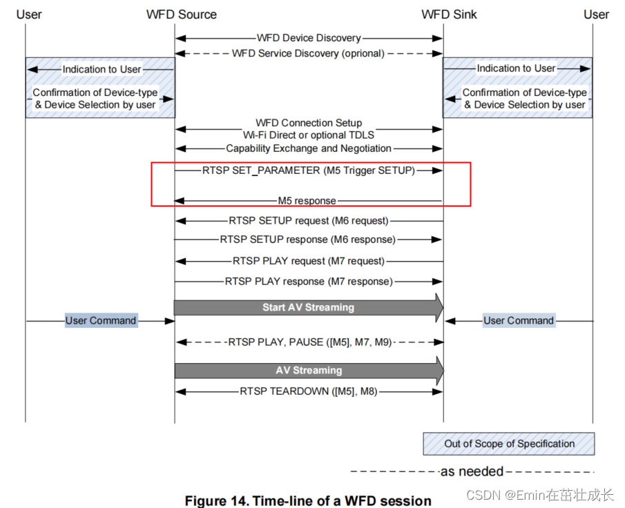
在M4阶段收到sink端的回应后,source即开始发送SETUP过程
status_t WifiDisplaySource::onReceiveM4Response(
        int32_t sessionID, const sp<ParsedMessage> &msg) {
    int32_t statusCode;
    if (!msg->getStatusCode(&statusCode)) {
        return ERROR_MALFORMED;
    }

    if (statusCode != 200) {
        return ERROR_UNSUPPORTED;
    }

    if (mUsingHDCP && !mHDCPInitializationComplete) {
        ALOGI("Deferring SETUP trigger until HDCP initialization completes.");

        mSetupTriggerDeferred = true;
        return OK;
    }
    //启动trigger setup流程
    return sendTrigger(sessionID, TRIGGER_SETUP);
}
status_t WifiDisplaySource::sendTrigger(
        int32_t sessionID, TriggerType triggerType) {
    AString body = "wfd_trigger_method: ";
    switch (triggerType) {
        case TRIGGER_SETUP:
            body.append("SETUP");
            break;
        case TRIGGER_TEARDOWN:
            ALOGI("Sending TEARDOWN trigger.");
            body.append("TEARDOWN");
            break;
        case TRIGGER_PAUSE:
            body.append("PAUSE");
            break;
        case TRIGGER_PLAY:
            body.append("PLAY");
            break;
        default:
            TRESPASS();
    }

    body.append("\r\n");

    AString request = "SET_PARAMETER rtsp://localhost/wfd1.0 RTSP/1.0\r\n";
    AppendCommonResponse(&request, mNextCSeq);

    request.append("Content-Type: text/parameters\r\n");
    request.append(AStringPrintf("Content-Length: %d\r\n", body.size()));
    request.append("\r\n");
    request.append(body);

    status_t err =
        mNetSession->sendRequest(sessionID, request.c_str(), request.size());

    if (err != OK) {
        return err;
    }

    registerResponseHandler(
            sessionID, mNextCSeq, &WifiDisplaySource::onReceiveM5Response);

    ++mNextCSeq;

    return OK;
}
source收到M5 setup trigger的回应后,接下来会有sink端发送M6的setup请求,此时source端会回应sink端的SETUP请求
这里的接收sink端SETUP请求,是在WifiDisplaySource::onReceiveClientData的回调函数中取掉消息的。消息链如下:
ANetWorkSession::Session:readMore()
-> WifiDisplaySource::onMessageReceived(const sp &msg)
-->case kWhatRTSPNotify
-->case ANetworkSession::kWhatData
--> onReceiveClientData(msg)
status_t WifiDisplaySource::onReceiveClientData(const sp<AMessage> &msg) {
    AString method;
    AString uri;
    data->getRequestField(0, &method);

    status_t err;
    //根据sink端的method,进行处理
    if (method == "OPTIONS") {
        err = onOptionsRequest(sessionID, cseq, data);
    } else if (method == "SETUP") {
        err = onSetupRequest(sessionID, cseq, data);
    } else if (method == "PLAY") {
        err = onPlayRequest(sessionID, cseq, data);
    } else if (method == "PAUSE") {
        err = onPauseRequest(sessionID, cseq, data);
    } else if (method == "TEARDOWN") {
        err = onTeardownRequest(sessionID, cseq, data);
    } else if (method == "GET_PARAMETER") {
        err = onGetParameterRequest(sessionID, cseq, data);
    } else if (method == "SET_PARAMETER") {
        err = onSetParameterRequest(sessionID, cseq, data);
    } else {
        sendErrorResponse(sessionID, "405 Method Not Allowed", cseq);
        err = ERROR_UNSUPPORTED;
    }
}
source端在收到sink端的SETUP请求后,进入onSetupRequest方法进行处理,这里面会对RTP传输的模式进行设置(UDP/TCP),随后创建音视频数据流的PlaybackSession,作为source与sink端之间的会话传输抽象,里面包含了数据获取,编码,打包等。随后发送对应的response给sink端。
在onSetupRequest里面,重点关注PlaybackSession的创建和初始化,这里可以说是source端与sink端音视频数据传输的起点
status_t WifiDisplaySource::onSetupRequest(
        int32_t sessionID,
        int32_t cseq,
        const sp<ParsedMessage> &data) {

   int32_t playbackSessionID = makeUniquePlaybackSessionID();

    sp<AMessage> notify = new AMessage(kWhatPlaybackSessionNotify, this);
    notify->setInt32("playbackSessionID", playbackSessionID);
    notify->setInt32("sessionID", sessionID);

    //创建会话交互的session,用于传输RTP流
    sp<PlaybackSession> playbackSession =
        new PlaybackSession(
                mOpPackageName, mNetSession, notify, mInterfaceAddr, mHDCP, mMediaPath.c_str());

    //将session也注册为线程looper的handler,可以处理Amessage
    looper()->registerHandler(playbackSession);

    AString uri;
    data->getRequestField(1, &uri);

    if (strncasecmp("rtsp://", uri.c_str(), 7)) {
        sendErrorResponse(sessionID, "400 Bad Request", cseq);
        return ERROR_MALFORMED;
    }

    if (!(uri.startsWith("rtsp://") && uri.endsWith("/wfd1.0/streamid=0"))) {
        sendErrorResponse(sessionID, "404 Not found", cseq);
        return ERROR_MALFORMED;
    }

    RTPSender::TransportMode rtcpMode = RTPSender::TRANSPORT_UDP;
    if (clientRtcp < 0) {
        rtcpMode = RTPSender::TRANSPORT_NONE;
    }

    // 初始化playbacksession
    status_t err = playbackSession->init(
            mClientInfo.mRemoteIP.c_str(),
            clientRtp,
            rtpMode,
            clientRtcp,
            rtcpMode,
            mSinkSupportsAudio,
            mUsingPCMAudio,
            mSinkSupportsVideo,
            mChosenVideoResolutionType,
            mChosenVideoResolutionIndex,
            mChosenVideoProfile,
            mChosenVideoLevel);

}
在PlaybackSession的初始化过程中,首先会创建一个MediaSender,这是一个用来发送媒体数据流的对象,这里面会去封装ts流,随后调用RTPSender将媒体流发送到sink端。随后调用setupPacketizer,进行源的添加(包括音频和视频源),紧接着异步初始化MediaSender:mMediaSender->initAsync,与client端即sink建立UDP/TCP连接
status_t WifiDisplaySource::PlaybackSession::init(
        const char *clientIP,
        int32_t clientRtp,
        RTPSender::TransportMode rtpMode,
        int32_t clientRtcp,
        RTPSender::TransportMode rtcpMode,
        bool enableAudio,
        bool usePCMAudio,
        bool enableVideo,
        VideoFormats::ResolutionType videoResolutionType,
        size_t videoResolutionIndex,
        VideoFormats::ProfileType videoProfileType,
        VideoFormats::LevelType videoLevelType) {
    sp<AMessage> notify = new AMessage(kWhatMediaSenderNotify, this);

    //创建mediasender
    mMediaSender = new MediaSender(mNetSession, notify);
    looper()->registerHandler(mMediaSender);

    mMediaSender->setHDCP(mHDCP);

    //setupPacketizer建立打包的对象,这里会去addVideosource和audiosource,获取屏幕和音频数据送到解码器
    status_t err = setupPacketizer(
            enableAudio,
            usePCMAudio,
            enableVideo,
            videoResolutionType,
            videoResolutionIndex,
            videoProfileType,
            videoLevelType);

    if (err == OK) {
        //初始化UDP/TCP连接
        err = mMediaSender->initAsync(
                -1 /* trackIndex */,
                clientIP,
                clientRtp,
                rtpMode,
                clientRtcp,
                rtcpMode,
                &mLocalRTPPort);
    }

    if (err != OK) {
        mLocalRTPPort = -1;

        looper()->unregisterHandler(mMediaSender->id());
        mMediaSender.clear();

        return err;
    }

    updateLiveness();

    return OK;
}
关键看setupPacketizer函数,这里面调用了addVideoSource和addAudioSource来初始化视频和音频流数据。
video的源数据即source端的屏幕数据,是来源于SurfaceFlinger图层叠加后的数据,在addVideoSource中,会创建一个SurfaceMediaSource对象,来接收当前屏幕数据。
status_t WifiDisplaySource::PlaybackSession::addVideoSource(
        VideoFormats::ResolutionType videoResolutionType,
        size_t videoResolutionIndex,
        VideoFormats::ProfileType videoProfileType,
        VideoFormats::LevelType videoLevelType) {
    size_t width, height, framesPerSecond;
    bool interlaced;
    CHECK(VideoFormats::GetConfiguration(
                videoResolutionType,
                videoResolutionIndex,
                &width,
                &height,
                &framesPerSecond,
                &interlaced));

    unsigned profileIdc, levelIdc, constraintSet;
    CHECK(VideoFormats::GetProfileLevel(
                videoProfileType,
                videoLevelType,
                &profileIdc,
                &levelIdc,
                &constraintSet));

    //创建接收屏幕数据的surface,直接获取surfaceflinger混合后的数据
    sp<SurfaceMediaSource> source = new SurfaceMediaSource(width, height);

    source->setUseAbsoluteTimestamps();

    //videoSource内部是自循环不断读取屏幕数据buffer,将source作为参数传入
    sp<RepeaterSource> videoSource =
        new RepeaterSource(source, framesPerSecond);

    size_t numInputBuffers;
    status_t err = addSource(
            true /* isVideo */, videoSource, true /* isRepeaterSource */,
            false /* usePCMAudio */, profileIdc, levelIdc, constraintSet,
            &numInputBuffers);

    if (err != OK) {
        return err;
    }

    err = source->setMaxAcquiredBufferCount(numInputBuffers);
    CHECK_EQ(err, (status_t)OK);

    mProducer = source->getProducer();

    return OK;
}
RepeaterSource在start中,调用传入的SurfaceMediaSource的start,读取屏幕数据,并通过postRead()来实现自循环读取buffer,以消息驱动方式进行
void RepeaterSource::postRead() {
    (new AMessage(kWhatRead, mReflector))->post();
}

void RepeaterSource::onMessageReceived(const sp<AMessage> &msg) {
    switch (msg->what()) {
        case kWhatRead:
        {
            //读取SurfaceMediaSource数据
            MediaBufferBase *buffer;
            status_t err = mSource->read(&buffer);

            ALOGV("read mbuf %p", buffer);

            Mutex::Autolock autoLock(mLock);
            if (mBuffer != NULL) {
                mBuffer->release();
                mBuffer = NULL;
            }
            mBuffer = buffer;
            mResult = err;
            mLastBufferUpdateUs = ALooper::GetNowUs();

            mCondition.broadcast();

            if (err == OK) {
                //自循环不断读取surface的buffer
                postRead();
            }
            break;
        }

        default:
            TRESPASS();
    }
}
//TODO : 分析数据通过MediaCodec,送入原始数据和获取编码数据。
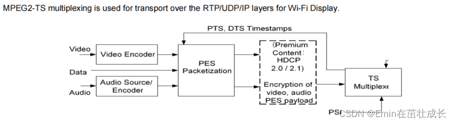
RTP与MPEG2-TS
Miracast底层的实现中,是采用RTP协议对MPEG2-TS数据包进行封装,其中MPEG2-TS又同时封装了Audio和Video两种ES(Elementary Stream)。其中Audio格式一般为AAC,Video则为H.264
RTP
实时传输协议(Real-time Transport Protocol)是一个网络传输协议,此协议详细说明了在互联网上传递音频和视频的标准数据包格式。RTP协议常用于流媒体系统(配合RTSP协议),且一般情况下,RTP会搭配RTCP协议一起使用
MPEG2-TS
MPEG2-TS传输流(MPEG-2 Transport Stream,又称MPEG-TS、MTS、TS)是一种传输和存储包含视频、音频与通信协议各种数据的标准格式,用于数字电视广播系统,如DVB、ATSC、ISDB、IPTV等等。其中1个TS承载多个子TS,通常子TS是分组化基本流(PES, Packetized elementary stream),分组化基本流上又承载着基本流(ES,Elementary Stream)。
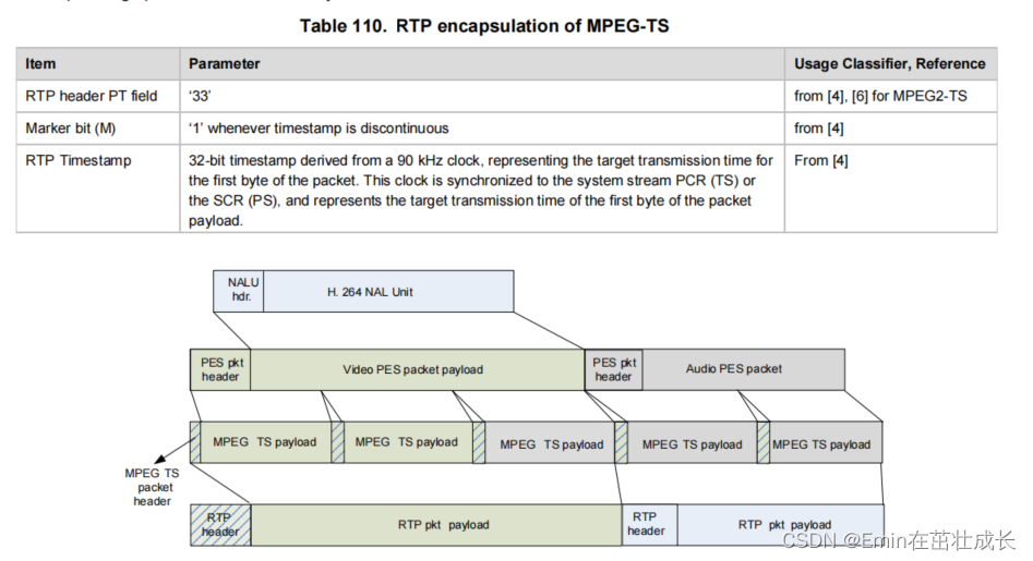
TS分组(TS Packet),长度固定为188字节,它是基本的传输单位。多个不同的ES的内容会分别被封装到TSP中通过同一个TS传输。每个TS分组以固定的同步字节起始,这个同步字节的值为0x47,它也是TS分组头的一部分。TS分组的固定头长度为4字节,其后为可选部分,为Payload或适配域
如下图所示,是一标准H264 NALU单元,一步步封装为RTP的数据包封装格式的过程:
总结
从RTP数据包解析出音视频的裸流,主要经过以下几个步骤:
- 解析RTP固定12字节头,取出其后的Payload数据(MPEG2-TS包)
- 以188B的大小裁剪出N个TS包
- 解析TS包,查找
PID=0的PAT包并解析,得到PMT的PID - 根据PID查找到PMT包并解析,得到
PCR_PID与音视频ES流的PID - 根据音视频ES流的PID解析出对应的音视频TS包
- 根据
Payload Unit Start Indicator字段,组装同一个PES下的TS包 - 对完整的PES包进行解析,得到
PTS/DTS与最终的音视频裸流数据,流程结束
WifiDisplay传输的流媒体格式如下:

WFD相关策略
比特率自动调节
出现如下log,看到码率下降,从2.5Mbps下降到1.5Mbps,注意2500000前面的减号,表示这个阶段下调码率,可能网络波动引起:
06-17 19:29:43.519217   481  3285 I NetworkSession: 729 datagrams remain queued.
06-17 19:29:43.519296   481  3285 I NetworkSession: -[2500000]--->[1500000]
06-17 19:29:43.520984   481  3288 W MediaCodec: mapFormat: no mediaType information
06-17 19:29:43.523605   481  3288 D CCodecConfig: c2 config diff is   c2::u32 coded.bitrate.value = 1500000
06-17 19:29:43.523605   481  3288 D CCodecConfig:   Buffer coded.init-data.value = {
06-17 19:29:43.523605   481  3288 D CCodecConfig:     00000000:  00 00 00 01 67 4d 00 29  96 54 02 80 2d 92 10 10  ....gM.).T..-...
06-17 19:29:43.523605   481  3288 D CCodecConfig:     00000010:  20 20 20 00 00 00 01 68  ee 3c 80                    ....h.<.
06-17 19:29:43.523605   481  3288 D CCodecConfig:   }
06-17 19:29:43.524367   481  3288 W ColorUtils: expected specified color aspects (0:0:0:0)
这里简单剖析这个动态码率计算的策略:
1.数据包分包,分为很多个Fragment
2.分包后的数据,向socke逐个写入
n = send(mSocket, datagram->data(), datagram->size(), 0);
3.首次发包失败,记录当前时间戳,然后进入下一次writemore循环重试
4.第二次发包失败,记录当前时间戳,如果发现当前丢包时间比上次丢包时间差大于1000ms,则降低一档码率
5.如果发包成功,同时之前出现丢包降档的情况,则判断当前时间与上次丢包的时间差是否大于8s,大于8s内一直没有丢包,则码率提高一档
Miracast source端分析调试
一些配合分析的TAG:
- WifiDisplayController:查看wifi display的状态,以及RTSP连接跟监听的端口ip
- WifiDisplaySource:查看RTSP协商的过程(通过the test xx)以及参数协商后的video,audio格式,编码参数等
打开Converter.cpp文件的调试开关,可以看到初始码率信息

分析连接流程
logcat -v time -s WifiDisplayController WifiDisplaySource RTPSender NetworkSession Converter
06-28 15:53:55.451 I/WifiDisplayController(  575): Connecting to Wifi display: 客厅电视
06-28 15:53:55.486 I/WifiDisplayController(  575): Initiated connection to Wifi display: 客厅电视
06-28 15:54:00.287 I/WifiDisplayController(  575): Connected to Wifi display: 客厅电视
06-28 15:54:00.287 I/WifiDisplayController(  575): Stopping Wifi display scan.
06-28 15:54:00.292 I/WifiDisplayController(  575): Listening for RTSP connection on 192.168.49.35:7236 from Wifi display: 客厅电视
06-28 15:54:00.297 E/WifiDisplaySource( 7246): the_test, 2
06-28 15:54:00.297 E/WifiDisplaySource( 7246): the_test, 4
06-28 15:54:01.056 I/NetworkSession( 7246): incoming connection from 192.168.49.1:41644 (socket 13)
06-28 15:54:01.057 I/NetworkSession( 7246): added clientSession 2
06-28 15:54:01.057 I/WifiDisplaySource( 7246): We now have a client (2) connected.
06-28 15:54:01.117 I/WifiDisplaySource( 7246): Picked video resolution 1280 x 800 p30
06-28 15:54:01.117 I/WifiDisplaySource( 7246): Picked AVC profile 1, level 1
06-28 15:54:01.117 I/WifiDisplaySource( 7246): Using AAC audio.
06-28 15:54:01.117 I/WifiDisplaySource( 7246): Sink does not support content protection.
06-28 15:54:01.405 W/RTPSender( 7246): Huh? Received data on RTP connection...
06-28 15:54:01.405 W/RTPSender( 7246): Huh? Received data on RTP connection...
06-28 15:54:01.405 I/WifiDisplaySource( 7246): Received PLAY request.
06-28 15:54:01.406 I/WifiDisplaySource( 7246): deferring PLAY request until session established.
06-28 15:54:01.408 I/WifiDisplayController(  575): Opened RTSP connection with Wifi display: 客厅电视
06-28 15:54:03.915 I/RTPSender( 7246): lost 99.22 % of packets during report interval.
出现如下日志,无法连接上sink端:
06-27 17:30:26.275 I/WifiDisplayController( 575): Timed out waiting for Wifi display RTSP connection after 30 seconds: 客厅电视
06-27 17:30:26.275 I/WifiDisplayController( 575): Wifi display connection failed!
06-27 17:30:26.275 I/WifiDisplayController( 575): Retrying Wifi display connection. Retries left: 2
06-27 17:30:26.275 I/WifiDisplayController( 575): Stopped listening for RTSP connection on 192.168.49.35:7236 from Wifi display: 客厅电视
等待RTSP incoming超时,一般这个时候需要排查sink端的连接状态,如下为WifiDisplayController.java相关代码:
// Step 6. Listen for incoming RTSP connection.
if (mConnectedDevice != null && mRemoteDisplay == null) {
    Inet4Address addr = getInterfaceAddress(mConnectedDeviceGroupInfo);
    if (addr == null) {
        Slog.i(TAG, "Failed to get local interface address for communicating "
               + "with Wifi display: " + mConnectedDevice.deviceName);
        handleConnectionFailure(false);
        return; // done
    }

    mWifiP2pManager.setMiracastMode(WifiP2pManager.MIRACAST_SOURCE);

    final WifiP2pDevice oldDevice = mConnectedDevice;
    final int port = getPortNumber(mConnectedDevice);
    final String iface = addr.getHostAddress() + ":" + port;
    mRemoteDisplayInterface = iface;

    Slog.i(TAG, "Listening for RTSP connection on " + iface
           + " from Wifi display: " + mConnectedDevice.deviceName);

    mRemoteDisplay = RemoteDisplay.listen(iface, new RemoteDisplay.Listener() {
        @Override
            public void onDisplayConnected(Surface surface,
                                           int width, int height, int flags, int session) {
            if (mConnectedDevice == oldDevice && !mRemoteDisplayConnected) {
                Slog.i(TAG, "Opened RTSP connection with Wifi display: "
                       + mConnectedDevice.deviceName);
                mRemoteDisplayConnected = true;
                mHandler.removeCallbacks(mRtspTimeout);

                if (mWifiDisplayCertMode) {
                    mListener.onDisplaySessionInfo(
                        getSessionInfo(mConnectedDeviceGroupInfo, session));
                }

                final WifiDisplay display = createWifiDisplay(mConnectedDevice);
                advertiseDisplay(display, surface, width, height, flags);
            }
        }

        @Override
            public void onDisplayDisconnected() {
            if (mConnectedDevice == oldDevice) {
                Slog.i(TAG, "Closed RTSP connection with Wifi display: "
                       + mConnectedDevice.deviceName);
                mHandler.removeCallbacks(mRtspTimeout);
                disconnect();
            }
        }

        @Override
            public void onDisplayError(int error) {
            if (mConnectedDevice == oldDevice) {
                Slog.i(TAG, "Lost RTSP connection with Wifi display due to error "
                       + error + ": " + mConnectedDevice.deviceName);
                mHandler.removeCallbacks(mRtspTimeout);
                handleConnectionFailure(false);
            }
        }
    }, mHandler, mContext.getOpPackageName());

    // Use extended timeout value for certification, as some tests require user inputs
    int rtspTimeout = mWifiDisplayCertMode ?
        RTSP_TIMEOUT_SECONDS_CERT_MODE : RTSP_TIMEOUT_SECONDS;

    mHandler.postDelayed(mRtspTimeout, rtspTimeout * 1000);
}

//超时的runnable
private final Runnable mRtspTimeout = new Runnable() {
    @Override
        public void run() {
        if (mConnectedDevice != null
            && mRemoteDisplay != null && !mRemoteDisplayConnected) {
            Slog.i(TAG, "Timed out waiting for Wifi display RTSP connection after "
                   + RTSP_TIMEOUT_SECONDS + " seconds: "
                   + mConnectedDevice.deviceName);
            handleConnectionFailure(true);
        }
    }
};
丢包分析
有些sink端支持在RTCP的RR包中,反馈两个RR包间隔内的丢包率,比如笔者在开发调试使用盒子作为sink段,该sink端就会通过RTCP包返回相应的丢包统计。这个时候可以通过logcat -v time -s RTPSender查看当前的丢包率。一般来说,丢包率不为0%的情况下,画面容易出现马赛克或者花屏
06-27 19:17:14.694 I/WifiDisplayController(  575): Initiated connection to Wifi display: 客厅电视
06-27 19:17:39.562 I/WifiDisplayController(  575): Connected to Wifi display: 客厅电视
06-27 19:17:39.562 I/WifiDisplayController(  575): Stopping Wifi display scan.
06-27 19:17:39.567 I/WifiDisplayController(  575): Listening for RTSP connection on 192.168.49.35:7236 from Wifi display: 客厅电视
06-27 19:17:39.570 E/WifiDisplaySource( 7246): the_test, 2
06-27 19:17:39.570 E/WifiDisplaySource( 7246): the_test, 4
06-27 19:17:40.405 I/WifiDisplaySource( 7246): We now have a client (2) connected.
06-27 19:17:40.551 I/WifiDisplaySource( 7246): Picked video resolution 1280 x 800 p30
06-27 19:17:40.551 I/WifiDisplaySource( 7246): Picked AVC profile 1, level 1
06-27 19:17:40.551 I/WifiDisplaySource( 7246): Using AAC audio.
06-27 19:17:40.551 I/WifiDisplaySource( 7246): Sink does not support content protection.
06-27 19:17:40.893 W/RTPSender( 7246): Huh? Received data on RTP connection...
06-27 19:17:40.893 W/RTPSender( 7246): Huh? Received data on RTP connection...
06-27 19:17:40.893 I/WifiDisplaySource( 7246): Received PLAY request.
06-27 19:17:40.893 I/WifiDisplaySource( 7246): deferring PLAY request until session established.
06-27 19:17:40.896 I/WifiDisplayController(  575): Opened RTSP connection with Wifi display: 客厅电视
06-27 19:17:43.211 I/RTPSender( 7246): lost 99.61 % of packets during report interval.
06-27 19:17:47.678 I/RTPSender( 7246): lost 0.00 % of packets during report interval.
06-27 19:17:51.246 I/RTPSender( 7246): lost 0.00 % of packets during report interval.
06-27 19:17:56.120 I/RTPSender( 7246): lost 3.91 % of packets during report interval.
06-27 19:18:01.263 I/RTPSender( 7246): lost 0.00 % of packets during report interval.
06-27 19:18:07.155 I/RTPSender( 7246): lost 0.00 % of packets during report interval.
06-27 19:18:13.215 I/RTPSender( 7246): lost 0.00 % of packets during report interval.
06-27 19:18:17.275 I/RTPSender( 7246): lost 0.00 % of packets during report interval.
06-27 19:18:21.540 I/RTPSender( 7246): lost 0.00 % of packets during report interval.
06-27 19:18:27.460 I/RTPSender( 7246): lost 0.00 % of packets during report interval.
06-27 19:18:33.594 I/RTPSender( 7246): lost 0.00 % of packets during report interval.
06-27 19:18:39.283 I/RTPSender( 7246): lost 0.00 % of packets during report interval.
06-27 19:18:43.191 I/RTPSender( 7246): lost 0.00 % of packets during report interval.
06-27 19:18:48.297 I/RTPSender( 7246): lost 0.00 % of packets during report interval.
06-27 19:18:53.829 I/RTPSender( 7246): lost 0.00 % of packets during report interval.
06-27 19:18:58.534 I/RTPSender( 7246): lost 0.00 % of packets during report interval.
06-27 19:19:02.525 I/RTPSender( 7246): lost 0.00 % of packets during report interval.
06-27 19:19:08.668 I/RTPSender( 7246): lost 0.00 % of packets during report interval.
06-27 19:19:12.665 I/RTPSender( 7246): lost 0.39 % of packets during report interval.
06-27 19:19:18.212 I/RTPSender( 7246): lost 2.73 % of packets during report interval.
06-27 19:19:24.363 I/RTPSender( 7246): lost 0.00 % of packets during report interval.
06-27 19:19:34.923 I/RTPSender( 7246): lost 0.00 % of packets during report interval.
06-27 19:19:40.381 I/RTPSender( 7246): lost 0.00 % of packets during report interval.
06-27 19:19:45.716 I/RTPSender( 7246): lost 0.00 % of packets during report interval.
06-27 19:19:51.049 I/RTPSender( 7246): lost 0.00 % of packets during report interval.
06-27 19:19:56.151 I/RTPSender( 7246): lost 0.00 % of packets during report interval.
06-27 19:20:01.164 I/RTPSender( 7246): lost 0.00 % of packets during report interval.
06-27 19:20:06.003 I/RTPSender( 7246): lost 0.00 % of packets during report interval.
06-27 19:20:11.751 I/RTPSender( 7246): lost 0.00 % of packets during report interval.
06-27 19:20:16.439 I/RTPSender( 7246): lost 0.00 % of packets during report interval.
06-27 19:20:20.418 I/RTPSender( 7246): lost 0.00 % of packets during report interval.
06-27 19:20:26.339 I/RTPSender( 7246): lost 0.00 % of packets during report interval.
06-27 19:20:32.006 I/RTPSender( 7246): lost 2.73 % of packets during report interval.
06-27 19:20:36.118 I/RTPSender( 7246): lost 0.00 % of packets during report interval.
dumpsys display
root:/ # dumpsys display |grep WifiDisplay
  mWifiDisplayScanRequestCount=0
  WifiDisplayAdapter
    mCurrentStatus=WifiDisplayStatus{featureState=3, scanState=0, activeDisplayState=0, activeDisplay=null, displays=[荣耀智慧屏X2 (12:38:1f:4f:c9:5a), isAvailable false, canConnect false, isRemembered true, QUAD-CORE H618 p2 (b4:29:46:9e:67:8f), isAvailable false, canConnect false, isRemembered true, 荣耀智慧屏X2 (12:2d:41:08:cb:1e), alias 荣耀智慧屏11, isAvailable false, canConnect false, isRemembered true, 客厅电视 (e2:76:d0:5b:8a:60), isAvailable true, canConnect true, isRemembered true, QUAD-CORE tv303 perf1 (18:9f:45:7d:47:b4), isAvailable true, canConnect true, isRemembered false], sessionInfo=WifiDisplaySessionInfo:
      mWifiDisplayOnSetting=true
      mAvailableWifiDisplayPeers: size=0
  0: mPid=575, mWifiDisplayScanRequested=false
  1: mPid=746, mWifiDisplayScanRequested=false
  2: mPid=764, mWifiDisplayScanRequested=false
  3: mPid=972, mWifiDisplayScanRequested=false
  4: mPid=1156, mWifiDisplayScanRequested=false
  5: mPid=1575, mWifiDisplayScanRequested=false
  6: mPid=1701, mWifiDisplayScanRequested=false
  7: mPid=3813, mWifiDisplayScanRequested=false
  8: mPid=4146, mWifiDisplayScanRequested=false
  9: mPid=4826, mWifiDisplayScanRequested=false
  10: mPid=4912, mWifiDisplayScanRequested=false
  11: mPid=14784, mWifiDisplayScanRequested=false
  12: mPid=25496, mWifiDisplayScanRequested=false
  13: mPid=27726, mWifiDisplayScanRequested=false
观察socket缓冲区
在前面的分析过程中我们知道,最终编码后的音视频数据流,是以RTP包的格式通过socket写入到网卡发送出去的,那么想要查看 socket 缓冲区,可以执行 netstat -nu 命令,-u表示udp
因为最终source端向sink端发送RTP包数据,是通过send方式写入socket缓冲区的
查看socket写缓冲区最大值:
cat /proc/sys/net/core/wmem_max
设置socket写缓冲区最大值:
echo xxx > /proc/sys/net/core/wmem_max
通过tcpdump + wireshark进行网络流数据分析
在分析卡顿/花屏的问题时,我们可以借助tcpdump + wireshark工具,直接将网络的RTP包dump为ts码流,直接进行播放,确认编码和打包后发送往sink端的码流数据是否正常,从而排查是源端编码发送问题,还是在sink端解码问题(当然还不能排除网络传输过程中的丢包)。抓包方式如下所示:
- 连接上投屏设备后,执行ipconfig命令,确认当前使用的p2p interface名称,如下所示则为“p2p-wlan0-5”
![[外链图片转存失败,源站可能有防盗链机制,建议将图片保存下来直接上传(img-6kUI8uvq-1662791209156)(Miracast流程分析.assets/image-20220704154746804.png)]](https://img-blog.csdnimg.cn/bf3b54301940480c9eaea49c2c2a8f20.png)
-
使用tcpdump命令抓取网络包,-i选项后面是ifconfig出来的p2p接口名,这里只抓取source端和sink端建立连接后的数据流,-w为保存的数据路径
tcpdump -i p2p-wlan0-5 -w /sdcard/xxxxx.cap
-
通过wireshark工具,打开tcpdump出来的文件
-
根据时间戳,选择对应的UDP报文(可能抓出来的报文中还有RTSP的),右键选择Decode As,添加一个item后选择当前解析为RTP


- 经过了步骤4的解码,这个时候输出的报文会解析为MPEG TS流的报文数据,如下所示:

- 这个时候选择电话-> RTP->流分析,此步完成后可以看到RTP数据包丢包率,延迟等信息报告


- 将RTP流保存为不同步的正向音频的,存为raw数据文件,该文件即为ts的码流文件,可以直接用potplayer之类的播放器载入播放


通过上面的步骤,我们可以直接获取导source发送的码流数据,确定当前发送的码流是否有花屏/卡顿/等现象,从而对问题点进行确认。同时通过RTP流的解析报告,我们也能看到丢包率,延迟等信息,与实际情况进行对比验证,方便问题定位。
上面的抓包过程是在设备连接后的阶段抓取的,所以主要是rtp payload,即ts码流数据。也可以通过tcpdump抓取从rtsp-rtp(rtcp)-mpegts的数据,分析整个链路过程的数据问题,这个时候为了方便,可以指定-i any获取所有网络接口数据,再进行过滤
tcpdump -i any -w xxxx
如下为过滤RTSP包出来:

查看RTP包负载编号,随后可以将RTP包负载解析为H264码流
编辑->首选项->protocols->H264,填入负载编号


TCPDUMP层级如下图所示分别为接收和发送在抓包流程,可以看到tcpdump的抓包点是在网络设备层中。用户态 tcpdump 命令是通过 socket 系统调用,在内核源码中用到的 ptype_all 中挂载了函数钩子上去。无论是在网络包接收过程中,还是在发送过程中,都会在网络设备层遍历 ptype_all 中的协议,并执行其中的回调。tcpdump 命令就是基于这个底层原理来工作的


常见花屏原因分析思路
-
接收端丢包
从我们自己的sink端可以反馈回丢包率,使用H616/H618进行测试,投屏首帧丢包率接近99%,造成花屏是必现。另外发现H616投屏时候,走的是2.4G信道
对比使用其他投屏器,投屏首帧花屏情况基本没有 -
发送端空中丢包/路由器状态
测试环境中,如果网络环境较复杂,路由器连接较多设备或者性能不足,也会造成发送后数据包丢失,造成花屏。建议在屏蔽房中进行测试,排除环境影响 -
pad端wifi模组性能较差,发送造成丢包
抓取tcpdump分析RTP包中AVC数据流,未看到编码后花屏的数据帧,说明miracast发送端写入网卡的数据是正常的,可能是模组本身性能导致发送延迟丢包
Miracast调优记录
socket发送端参数优化
从日志中看到,在调用socket send发送RTP包过程中,当负载或者数据量较大时,会出现较多的send函数返回Try again,即发送端缓存不足的情况,因此:
(1)增大socket发送端buffer,原来为256K,申请到2M,结合瞬时的带宽峰值来确定
(2) socket网络参数优化
TODO…


 1586
1586


 被折叠的 条评论
为什么被折叠?
被折叠的 条评论
为什么被折叠?
 到【灌水乐园】发言


