


一、存储器介绍
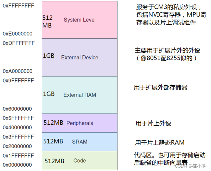
由上图可以看出片上外设所使用的地址从0x40000000~0x5FFFFFFF,即编程的根本就是操作该区间的寄存器。
二、函数功能原理分析
1、分析时钟开启函数 RCC_APB2PeriphClockCmd(RCC_APB2Periph_GPIOC, ENABLE);
结论 *(unsigned int*)(0x40021018)|=0x10 0x40021018=x40000000+0x020000+0x10000+x018
#define RCC_APB2Periph_GPIOC ((uint32_t)0x00000010)
查询中文参考手册IOPCEN在位4,故其值为0x10
typedef enum {DISABLE = 0, ENABLE = !DISABLE} FunctionalState;
void RCC_APB2PeriphClockCmd(uint32_t RCC_APB2Periph, FunctionalState NewState)
{
/* Check the parameters */ 检查输入参数是否错误
assert_param(IS_RCC_APB2_PERIPH(RCC_APB2Periph));
assert_param(IS_FUNCTIONAL_STATE(NewState));
if (NewState != DISABLE) 判断不是使能
{
RCC->APB2ENR |= RCC_APB2Periph; 或等于 将原始数据对照操作数为1的位置1
}
else
{
RCC->APB2ENR &= ~RCC_APB2Periph; 与等于 取反 1.将操作数逐位取反 2.与原数据进行与操作 即将原始数据对照操作数为1的位置0
}
}
#define RCC ((RCC_TypeDef *) RCC_BASE)
typedef struct
{
__IO uint32_t CR;
__IO uint32_t CFGR;
__IO uint32_t CIR;
__IO uint32_t APB2RSTR;
__IO uint32_t APB1RSTR;
__IO uint32_t AHBENR;
__IO uint32_t APB2ENR;
__IO uint32_t APB1ENR;
__IO uint32_t BDCR;
__IO uint32_t CSR;
#ifdef STM32F10X_CL
__IO uint32_t AHBRSTR;
__IO uint32_t CFGR2;
#endif /* STM32F10X_CL */
#if defined (STM32F10X_LD_VL) || defined (STM32F10X_MD_VL) || defined (STM32F10X_HD_VL)
uint32_t RESERVED0;
__IO uint32_t CFGR2;
#endif /* STM32F10X_LD_VL || STM32F10X_MD_VL || STM32F10X_HD_VL */
} RCC_TypeDef;
结构体定义的顺序与中文手册6.3偏移地址顺序保持一致,且每一个成员占32位。结构体成员的地址就按着结构体首地址依次排列,所以就实现了地址的自动偏移。
通过GPIO端的地址,我们可以发现相邻两个寄存器之间偏移0x04,而且一个寄存器存储32位,如果真是一个地址存储32位话,那偏移应该是0x01,所以我们得出结论在计算机中一个地址,代表一个字节(1Byte),32位刚好表示4个字节,刚好偏移0x04。即RCC_APB2ENR偏移地址:0x18
探索STM32地址与偏移_stm32单片机地址偏移是4_沙漠那点绿的博客-CSDN博客
#define RCC_BASE (AHBPERIPH_BASE + 0x1000)
#define AHBPERIPH_BASE (PERIPH_BASE + 0x20000)
由中文参考手册28页表1可以看出复位和时钟控制(RCC)基地址为0x40021000
#define PERIPH_BASE ((uint32_t)0x40000000) /*!< Peripheral base address in the alias region */
由权威指南可以得到片上外设的基地址是0x40000000
2、分析初始化结构体 GPIO_InitTypeDef GPIO_InitStructure;
typedef struct
{
uint16_t GPIO_Pin; /*!< Specifies the GPIO pins to be configured.
This parameter can be any value of @ref GPIO_pins_define */
GPIOSpeed_TypeDef GPIO_Speed; /*!< Specifies the speed for the selected pins.
This parameter can be a value of @ref GPIOSpeed_TypeDef */
GPIOMode_TypeDef GPIO_Mode; /*!< Specifies the operating mode for the selected pins.
This parameter can be a value of @ref GPIOMode_TypeDef */
}GPIO_InitTypeDef;
结构体由三个成员 GPIO_Pin_x在stm32f10x_gpio.h 127行到143行声明 GPIO_Pin_13 = 0x2000
typedef enum
{
GPIO_Speed_10MHz = 1,
GPIO_Speed_2MHz,
GPIO_Speed_50MHz
}GPIOSpeed_TypeDef;
成员值为+1时后续省略不写
typedef enum
{ GPIO_Mode_AIN = 0x0, 0000000 模拟输入
GPIO_Mode_IN_FLOATING = 0x04, 0000100 浮空输入
GPIO_Mode_IPD = 0x28, 0101000 下拉输入
GPIO_Mode_IPU = 0x48, 1001000 上拉输入
GPIO_Mode_Out_OD = 0x14, 0010100 开漏输出
GPIO_Mode_Out_PP = 0x10, 0010000 推挽输出
GPIO_Mode_AF_OD = 0x1C, 0011100 复用开漏输出
GPIO_Mode_AF_PP = 0x18 0011000 复用推挽输出
}GPIOMode_TypeDef;
3、分析初始化函数 GPIO_Init(GPIOC, &GPIO_InitStructure);
#define GPIOC ((GPIO_TypeDef *) GPIOC_BASE)
typedef struct
{
__IO uint32_t CRL; 低8位模式配置 4位配置一个GPIO口的模式
__IO uint32_t CRH; 低8位模式配置 4位配置一个GPIO口的模式
__IO uint32_t IDR; 16位端口输入寄存器
__IO uint32_t ODR; 16位端口输出寄存器
__IO uint32_t BSRR; 端口位设置清除寄存器高16位设置 低16位清除
__IO uint32_t BRR; 端口位清除寄存器 低16位清除 高16位保留
__IO uint32_t LCKR; 端口配置锁定寄存器 低16位 位16位锁 具体参阅中文参考手册116
} GPIO_TypeDef;
#define GPIOC_BASE (APB2PERIPH_BASE + 0x1000)
#define APB2PERIPH_BASE (PERIPH_BASE + 0x10000)
#define PERIPH_BASE ((uint32_t)0x40000000) /*!< Peripheral base address in the alias region */
根据前述分析GPIOC_BASE=0x40000000+0x10000+0x1000=0x40011000
查询中文参考手册GPIOC的起始地址为0x40011000
处理GPIO_MODE和GPIO_Speed成员
currentmode = ((uint32_t)GPIO_InitStruct->GPIO_Mode) & ((uint32_t)0x0F);取模式的后四位
模式配置数据后4位为中文参考手册114页 CNFy[1:0]MODEy[1:0] 后两位都是配置的0 通过第5位是否为1来判断是否为输出模式
if ((((uint32_t)GPIO_InitStruct->GPIO_Mode) & ((uint32_t)0x10)) != 0x00) 判断是否为输出模式
{
/* Check the parameters */
assert_param(IS_GPIO_SPEED(GPIO_InitStruct->GPIO_Speed));
/* Output mode */
currentmode |= (uint32_t)GPIO_InitStruct->GPIO_Speed;将输出速度叠加上去
}
处理GPIO_Pin成员
if (((uint32_t)GPIO_InitStruct->GPIO_Pin & ((uint32_t)0x00FF)) != 0x00)判断是否有低8位成员
{
tmpreg = GPIOx->CRL;不能影响原有GPIO状态,所以需要取出原有PGIO状态
for (pinpos = 0x00; pinpos < 0x08; pinpos++)循环8次判读所有低八位
{
pos = ((uint32_t)0x01) << pinpos;左移次数位 对应GPIO_Pin
/* Get the port pins position */
currentpin = (GPIO_InitStruct->GPIO_Pin) & pos; 取GPIO_Pin的循环次数对应位 给if判断用
if (currentpin == pos)判断该GPIO_Pin是否被选择
{
pos = pinpos << 2;相当于十进制乘4的意思
/* Clear the corresponding low control register bits */
pinmask = ((uint32_t)0x0F) << pos;把1111左移到Pin的四个对应位
tmpreg &= ~pinmask;或等于 取反 清除对应GPIO_Pin的设置
/* Write the mode configuration in the corresponding bits */
tmpreg |= (currentmode << pos);或等于 把之前模式的四个位currentmode左移到GPIO_Pin的对应位置或进去写在中间变量的
/* Reset the corresponding ODR bit */
if (GPIO_InitStruct->GPIO_Mode == GPIO_Mode_IPD)
{
GPIOx->BRR = (((uint32_t)0x01) << pinpos);BRR低 16 位用于设置 GPIO 口对应位输出低电平。高 16 位保留地址,读写无效。
}
else
{
/* Set the corresponding ODR bit */
if (GPIO_InitStruct->GPIO_Mode == GPIO_Mode_IPU)
{
GPIOx->BSRR = (((uint32_t)0x01) << pinpos);对寄存器高 16位 写1 对应管脚为低电平,对寄存器低16位写1对应管脚为高电平。写 0 ,无动作
此两行if为上拉输入/下拉输入配置 中文参考手册 表17有说明
STM32I/O口配置上拉下拉输入寄存器版_俗世老道的博客-CSDN博客
}
}
}
}
GPIOx->CRL = tmpreg;将中间变量写入进行配置
}
4、GPIO口的读写函数
在stm32f10x_gpio.h第349行开始有所有关于GPIO口操作的函数声明,在其对应的.c文件可以看到所有函数程序,基本上就是通过结构体在操作。
5、一些通过重定义功能读写GPIO口的操作
#define LED_GPIO GPIOC
#define LED_Pin GPIO_Pin_13
#define LED1_ON GPIO_SetBits(LED_GPIO,LED_Pin) //LED开
#define LED1_OFF GPIO_ResetBits(LED_GPIO,LED_Pin) //LED关
#define LED2_ON GPIO_WriteBit(LED_GPIO,LED_Pin,(BitAction)(1)) //LED开
#define LED2_OFF GPIO_WriteBit(LED_GPIO,LED_Pin,(BitAction)(0)) //LED关
#define LED2_SW(x) GPIO_WriteBit(LED_GPIO,LED_Pin,(BitAction)(x)) //LED 0关 其余开
#define LED2_Turn GPIO_WriteBit(LED_GPIO,LED_Pin,(BitAction)(GPIO_ReadOutputDataBit(LED_GPIO,LED_Pin)-1)) //LED 0关 其余开
#define LED3_ON GPIO_Write(GPIOC, GPIO_ReadOutputData(LED_GPIO)|GPIO_Pin_13) //LED开
#define LED3_OFF GPIO_Write(GPIOC, GPIO_ReadOutputData(LED_GPIO)&~GPIO_Pin_13) //LED关
#define LED3_Turn GPIO_Write(GPIOC, GPIO_ReadOutputData(LED_GPIO)^GPIO_Pin_13) //LED关


 1884
1884


 被折叠的 条评论
为什么被折叠?
被折叠的 条评论
为什么被折叠?
 到【灌水乐园】发言


