


 本文详细介绍STM32F103RB微控制器的开发流程,包括MDK-Arm安装、项目创建、GPIO配置及USART串口通信。提供从软件环境搭建到硬件接口编程的全面指导。
Update Record
| Version | Date | Author | Description |
|---|---|---|---|
| 1.0.0 | 2019-07-12 | Wintrue | Create |
1 Install&Configuration
1.1 Package
官网 https://www.keil.com/download/product/ 提供了MDK-Arm免费下载
作者这里使用了5.23版本的MDK。
1.2 Install
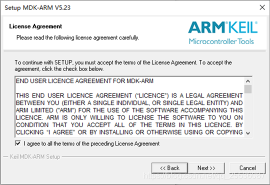
双击安装包,进行安装前的准备,遇到下图选择同意。
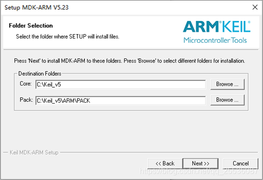
安装路径选择,作者直接默认全部安装在C盘。
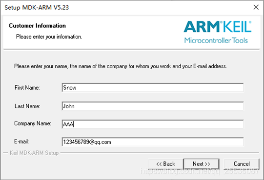
客户信息只需格式正确即可。
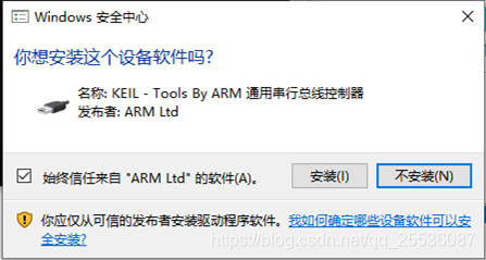
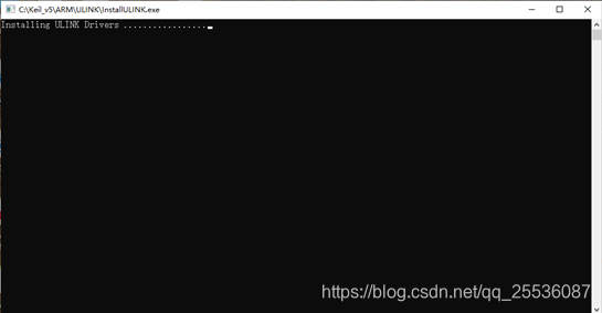
安装过程中,会自动请求安装一些驱动,若在不知该驱动为什么服务的话,一律选择安装即可。
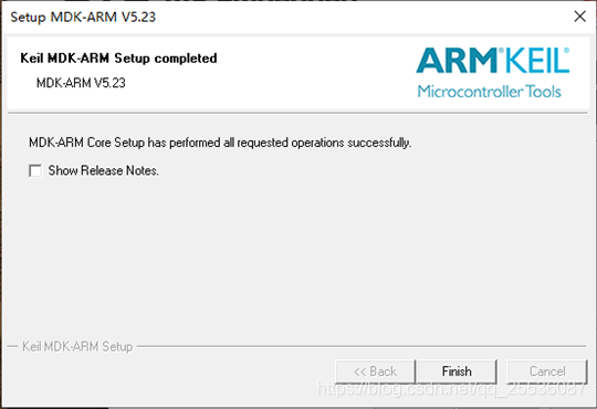
安装完成则会弹出下面界面,不用选择Show Release Notes,直接Finish。
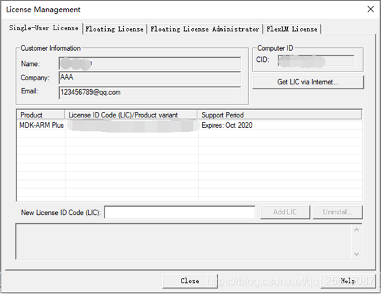
1.3 License 安装
打开keil—>File —>License Management进行license安装,复制CID,使用CID得到LIC 填入LIC,点击Add LIC,关闭窗口。
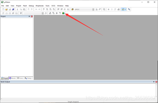
第一次打开keil,会弹出设备包安装工具(若没弹出看下一步),点击OK,该工具在线安装需要等待片刻,左边会加载完整安装目录。
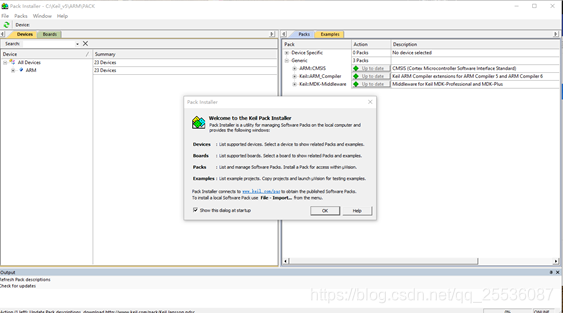
如果无意关了该界面或者未弹出,可以在直接打开keil,点击如下指示的图标。
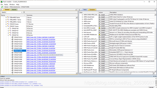
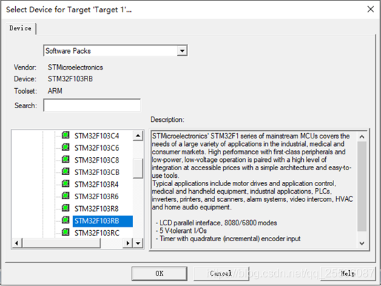
加载完毕后选择我们需要的芯片(这里为STMicroelectronics —>STM32F1 Series—>STM32F103 —>STM32F103RB)。然后找到DFP文件进行安装(这里为STM32F1xxDFP)
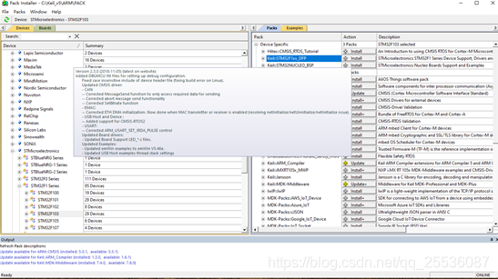
至此安装过程完毕,打开keil。

2 Start a New Project
2.1 New Project
进入keil后如下所示。
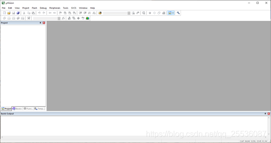
开始新建一个工层,打开project —>New uVersion Project。

选择合适的文件夹保存工程,注意新建工程不会新建根目录,该文件夹会被完全占用。
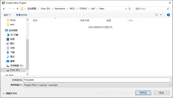
保存后,选择芯片
OK之后会出现库配置,在这里选择的话,既不用配置复杂的启动文件,分组,头文件,宏定义等,而且功能十分强大,包含了大量的库文件,而且还有依赖校验功能帮助使用者选择合适的库文件。
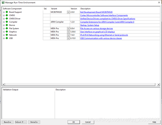
如下,为一个一个简单的模板工程配置了必须的CMSIS中的CORE,Device中的Startup和StdPeriph Drivers文件夹下的所有文件,这些库文件在工程进行中也可以更改,也可以在工程完成后去掉不必要的库,节省Flash空间。
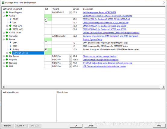
加入好库文件的工程如下

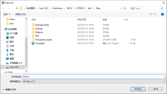
然后把我们自己的,工程必须的main.c文件加入进去。首先新建一个空白main.c文件。
保存在项目文件夹下一个合适的地方(作者保存在了工程根目录下)。
然后还需要将main.c 文件加入到工程,直接右击Target选择Manage Project items…,进入管理界面
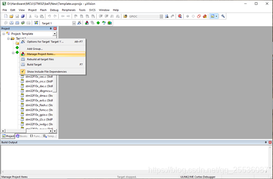
如下为管理界面,其中三个栏目下的内容皆可自由编辑。
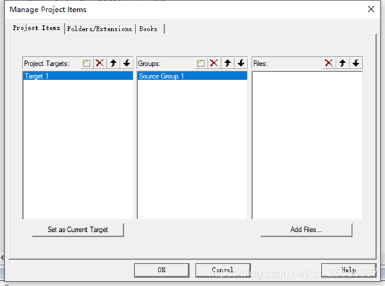
我们把main.c添加到Target 1的Source Group 1中,直接点击Add Files。
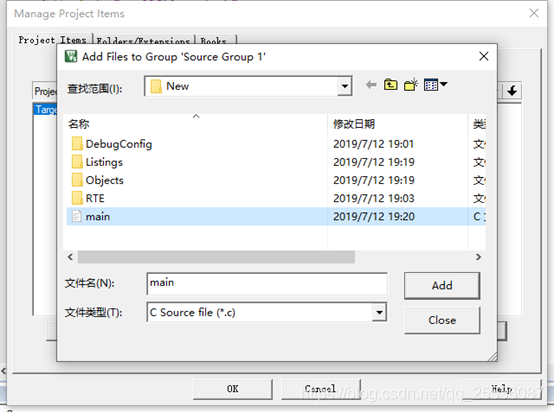
添加进去后,如下所示。需要注意的是,以后添加进工程的任何c文件皆需要这一步来添加进来,多的话可以在Group栏目下多分几个组。而头文件只需要加入路径即可,操作方法在后面会提及。
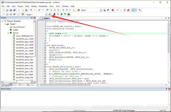
 然后,工程还需要一些配置。如下点击该图标进入配置界面。
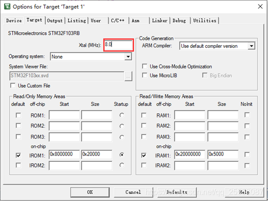
首先,将Target栏中的晶振频率改为8.0MHz。
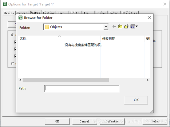
然后在Output栏下,点击上面框中按钮可以配置编译生成的文件存放于何处,可以不用配置,勾选生成HEX文件,此文件可以使用各种通用烧录软件给芯片下载程序。在此教程中不涉及该文件的使用。
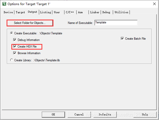
可以看到生成目标文件的文件夹默认在根目录的Objects文件夹下。
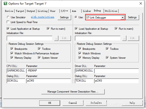
然后,进行调试和烧录的配置,我们使用的调试工具为ST-LINK V2,在Debug栏下选择如下。
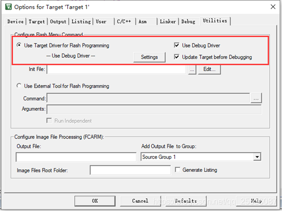
Utilities栏下可以选择烧录方式,我们可以不用配置其他工具,直接使用keil就好。配置如下。
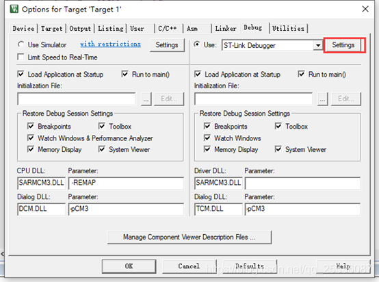
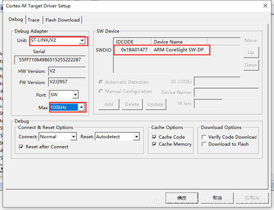
然后进入如下所示的Settings(和Utilities栏中的是相同的)
确认调试工具是否正常,如下为连接正常,不同调试工具的序列号可能不一样,Port一定要选择SW,MAX不能选择太大。
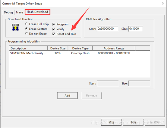
接着进入另一个选项页,记得勾选Reset and Run。这样下载后会自动开始运行程序。
其他可以使用默认配置,如果有需要则按需要进入再配置。另外,新添加的头文件需要在C/C++一栏下添加路径。
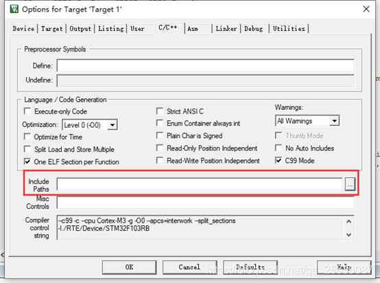
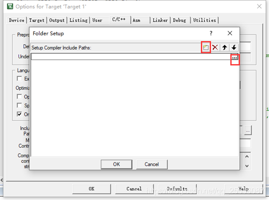
如下建立并选择路径。整个项目的宏定义也在C/C++一栏下添加,
2.2 Build Project
在刚才建立的main.c中添加以下内容:
#include "stm32f10x_gpio.h"
void delay(vu32 nCount)
{
  vu32 index = 0;
  for(index = (34000 * nCount); index != 0; index--)
  {
  }
}
void GPIOB_Set(uint16_t pin){
	GPIO_InitTypeDef  GPIO_InitStructure;
  /* Enable the GPIO Clock */
  RCC_APB2PeriphClockCmd(RCC_APB2Periph_GPIOB , ENABLE);
  /* Configure the GPIO pin */
  GPIO_InitStructure.GPIO_Pin = pin;
  GPIO_InitStructure.GPIO_Mode = GPIO_Mode_Out_PP;
  GPIO_InitStructure.GPIO_Speed = GPIO_Speed_50MHz;
  GPIO_Init(GPIOB, &GPIO_InitStructure);
}
int main(void){
	GPIOB_Set(GPIO_Pin_0);
	while(1){
	GPIO_SetBits(GPIOB, GPIO_Pin_0);
	delay(300);
	GPIO_ResetBits(GPIOB, GPIO_Pin_0);
	delay(100);
	}
}
#ifdef  USE_FULL_ASSERT
/**
  * @brief  Reports the name of the source file and the source line number
  *         where the assert_param error has occurred.
  * @param  file: pointer to the source file name
  * @param  line: assert_param error line source number
  * @retval None
  */
void assert_failed(uint8_t* file, uint32_t line)
{
  /* User can add his own implementation to report the file name and line number,
     ex: printf("Wrong parameters value: file %s on line %d\r\n", file, line) */

  /* Infinite loop */
  while (1)
  {
  }
}
#endif
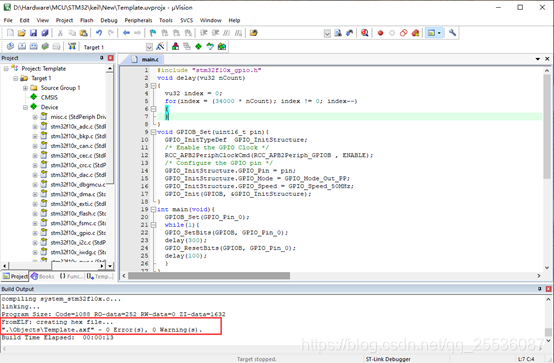
该文件的作用是让开发板的测试灯[PB0]一长一短的进行闪烁,启动部分代码在工程建立的时候就已经配置了(Startup中的汇编文件),程序开始的地方并不是main函数,而是启动文件,启动好后程序的入口才开始转入main函数。
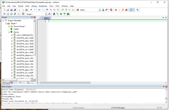
保存后,点击build 图标或者选择project —> build,如果已经build过了,可以选择rebuild
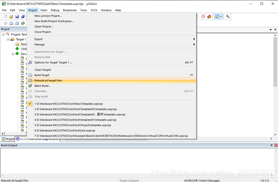
如果出现如下信息,则说明编译链接均正常无误,可以进行下一步。
3 Debug&Flash
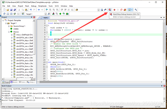
3.1 Debug
如下所示,点击该按钮进入调试模式,退出时同样点击该按钮。
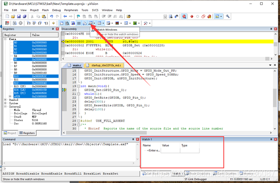
如下图所示,keil自带的调试工具具有强大的功能,可以进行单步调试,同步汇编,断点设置,数据观察窗,逻辑分析,输出波形等等。
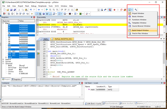
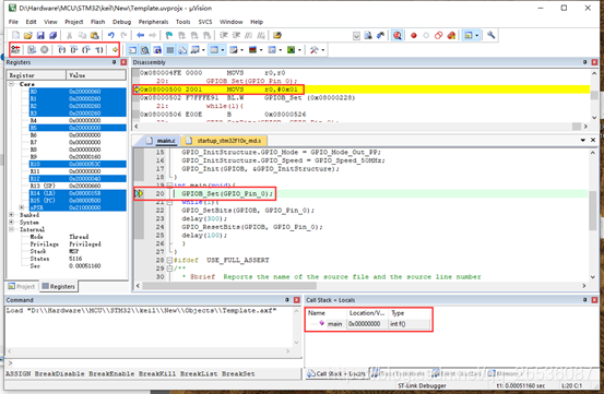
需要注意的是,同步调试一般不会将程序烧录给芯片,这与BOOT设置也有关。
3.2 Flash
烧录时,点击如下所示按钮即可
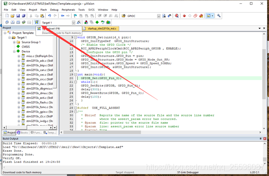
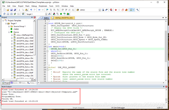
出现如下所示信息说明程序烧录成功,需要注意的是如果没设置烧录完毕重启的话,需要手动按下开关重启以后生效。
4 Example
4.1 Usart
STM32F103有三个USART外设,下面以USART1为例,进行配置:
#define USART1_GPIO 			GPIOA
#define USART1_TX 				GPIO_Pin_9
#define USART1_RX 				GPIO_Pin_10
#define USART1_GPIO_CLK 	RCC_APB2Periph_GPIOA
#define USART1_PORT_CLK 	RCC_APB2Periph_USART1
void USART1_Init(void){
USART_InitTypeDef USART_InitStructure;//usart配置结构体
GPIO_InitTypeDef GPIO_InitStructure;// usart所需引脚配置
  /* Enable GPIO clock */
  RCC_APB2PeriphClockCmd(USART1_GPIO_CLK, ENABLE);
  /* Configure USART Tx as alternate function push-pull */
  //GPIO_InitStructure.GPIO_Mode = GPIO_Mode_Out_PP;
GPIO_InitStructure.GPIO_Mode = GPIO_Mode_AF_PP;
  GPIO_InitStructure.GPIO_Pin = USART1_TX;
  GPIO_InitStructure.GPIO_Speed = GPIO_Speed_50MHz;
  GPIO_Init(USART1_GPIO, &GPIO_InitStructure);
  /* Configure USART Rx as input floating */
  GPIO_InitStructure.GPIO_Mode = GPIO_Mode_IN_FLOATING;
  GPIO_InitStructure.GPIO_Pin = USART1_RX;
  GPIO_Init(USART1_GPIO, &GPIO_InitStructure);

	  /* Enable UART clock */
  RCC_APB2PeriphClockCmd(USART1_PORT_CLK, ENABLE);
	USART_InitStructure.USART_BaudRate = 115200;
  USART_InitStructure.USART_WordLength = USART_WordLength_8b;
  USART_InitStructure.USART_StopBits = USART_StopBits_1;
  USART_InitStructure.USART_Parity = USART_Parity_No;
  USART_InitStructure.USART_HardwareFlowControl = USART_HardwareFlowControl_None;
  USART_InitStructure.USART_Mode = USART_Mode_Rx | USART_Mode_Tx;
	/* USART configuration */
  USART_Init(USART1, &USART_InitStructure);
	USART_ITConfig(USART1, USART_IT_RXNE, ENABLE);							//开启接收中断
	//USART_ITConfig(USART1, USART_IT_IDLE, ENABLE);
  /* Enable USART */
  USART_Cmd(USART1, ENABLE);
}
通过下面的程序,可以将USART1的数据发送映射到printf函数
#include <stdio.h>
#ifdef __GNUC__
  /* With GCC/RAISONANCE, small printf (option LD Linker->Libraries->Small printf
     set to 'Yes') calls __io_putchar() */
  #define PUTCHAR_PROTOTYPE int __io_putchar(int ch)
#else
  #define PUTCHAR_PROTOTYPE int fputc(int ch, FILE *f)
#endif /* __GNUC__ */
	struct __FILE
{
	int a;
};

FILE __stdout;
void _sys_exit(int x)
{
}
PUTCHAR_PROTOTYPE
{
  /* Place your implementation of fputc here */
  /* e.g. write a character to the USART */
  USART_SendData(USART1, (uint8_t) ch);

  /* Loop until the end of transmission */
  while (USART_GetFlagStatus(USART1, USART_FLAG_TC) == RESET)
  {}
  return ch;
}
调用如下:
#include <stdio.h>
int main(){
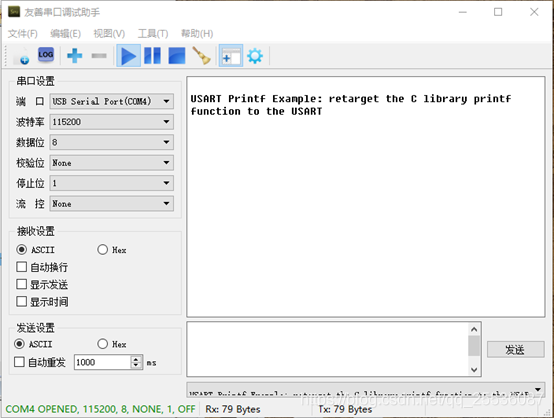
printf("\n\rUSART Printf Example: retarget the C library printf function to the USART\n\r");
return 0;
}
结果如下:
实际应用中我们需要非阻塞的接收串口数据,此处我们借助了其接收中断。
代码如下:
#define RXBUF2_MAX 256 //定义为256时,uint8_t不用判断是否溢出,自动从0开始
char RxUBuf1[RXBUF1_MAX];
static uint8_t Num_U1RxByte = 0;
static uint8_t U1RxF = 0;
static uint8_t U1RxL = 0;

char USART1_ReadByte(void){
	if(Num_U1RxByte == 0) return '\0';
	Num_U1RxByte--;
	return RxUBuf1[U1RxF++];
}
uint8_t USART1_RecNum(void){
		return Num_U1RxByte;
}

char USART1_SendChar(char ch){
	  USART_SendData(USART1, (uint8_t) ch);

  /* Loop until the end of transmission */
  while (USART_GetFlagStatus(USART1, USART_FLAG_TC) == RESET)
  {}
  return ch;
}

void USART1_IRQHandler(void){

	if(USART_GetITStatus(USART1, USART_IT_RXNE) != RESET)		//判断是否为接收中断
	{
		RxUBuf1[U1RxL++] = USART_ReceiveData(USART1);				  //读取接收到的字节数据
		if(Num_U1RxByte < 255)Num_U1RxByte++;
		else{
			U1RxF++; //当buffer满了丢弃最先收到的1个数据
		}
	}
}
使用示例:
int main(void){
	int i = 0;
	GPIO_Conf(LED_PORT,LED0_PIN|LED1_PIN);
	USART1_Init();
	while(1){
	GPIO_SetBits(LED_PORT, LED0_PIN);
	GPIO_ResetBits(LED_PORT, LED1_PIN);
	delay(30);
	GPIO_SetBits(LED_PORT, LED1_PIN);
	GPIO_ResetBits(LED_PORT, LED0_PIN);
	delay(10);
	i = USART1_RecNum();
	while(i--){
		USART1_SendChar(USART1_ReadByte());
	}
	}
return 0;
}
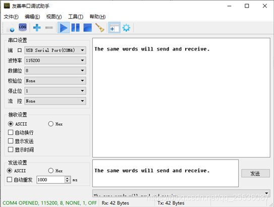
结果如下:
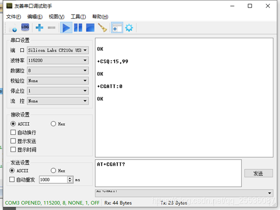
以同样的方式配置USART2,用下面的程序则可以直接通过串口调试助手跟NB-IoT模组进行通信。
int main(void){
	int i = 0;
	GPIO_Conf(LED_PORT,LED0_PIN|LED1_PIN);
	USART1_Init();
	USART2_Init();
	NVIC_Config();
	while(1){
	GPIO_SetBits(LED_PORT, LED0_PIN);
	GPIO_ResetBits(LED_PORT, LED1_PIN);
	delay(30);
	GPIO_SetBits(LED_PORT, LED1_PIN);
	GPIO_ResetBits(LED_PORT, LED0_PIN);
	delay(10);
	i = USART1_RecNum();
	while(i--){
		USART2_SendChar(USART1_ReadByte());
	}

	i = USART2_RecNum();
	while(i--){
		USART1_SendChar(USART2_ReadByte());
	}
	}
}
与NB-IoT模组通信结果如下所示:
完整的测试工程代码见:https://github.com/Magelgit/KeilforSTMF103RB


 5152
5152

 被折叠的 条评论
为什么被折叠?
被折叠的 条评论
为什么被折叠?
 到【灌水乐园】发言


