


疫情期间,指夹式血氧检测仪全网脱销,好不容易在某多多上买到一个,发现检测值很不靠谱,于是尝试DIY了一个。
一、设计思路
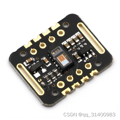
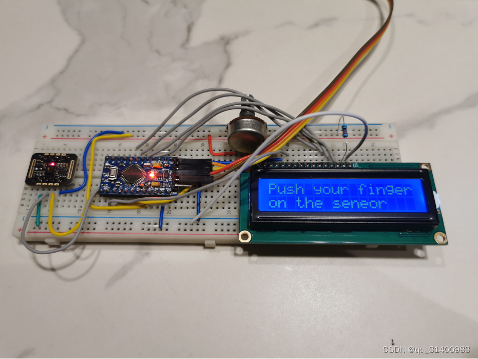
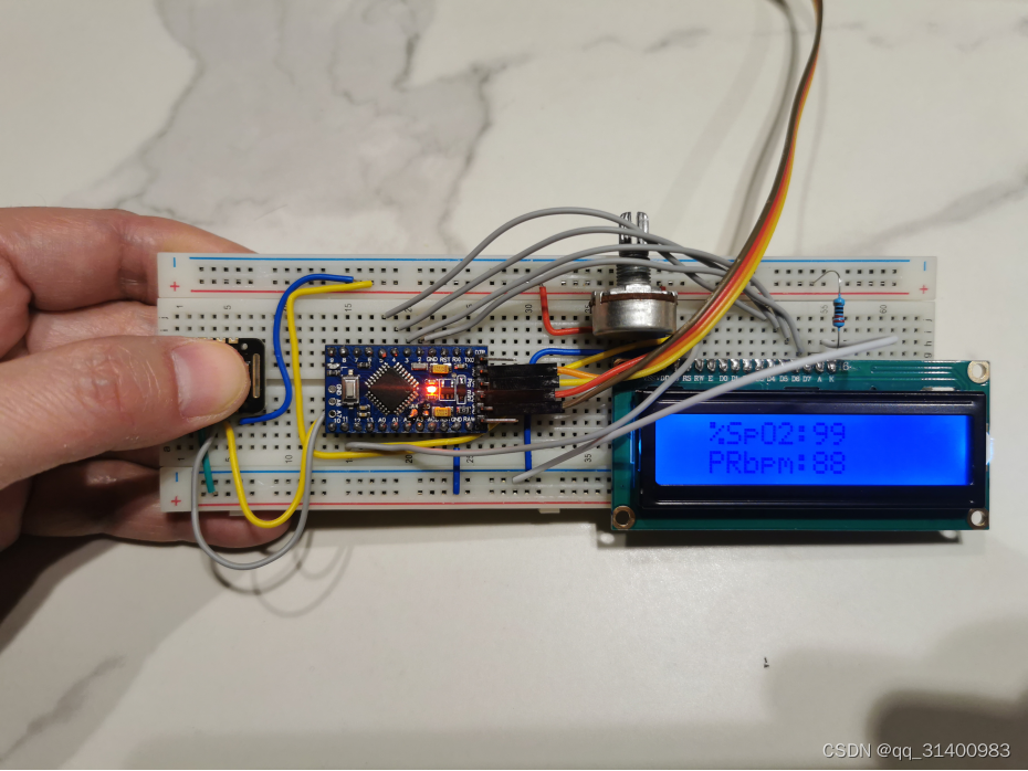
将MAX30102心率血氧传感器采样信息输入到Arduino Pro Mini单片机,把经计算后的心率、血氧数据显示到LCD1602显示屏。
二、软硬件准备
1、硬件:
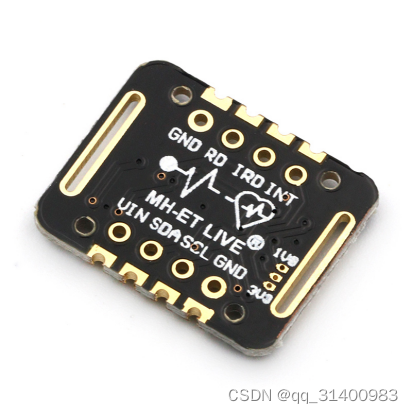
MAX30102心率血氧传感器
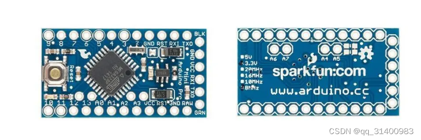
Arduino Pro Mini单片机
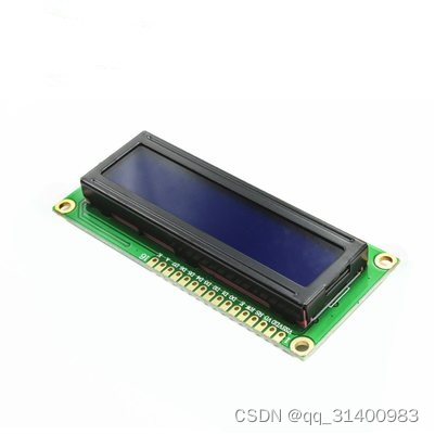
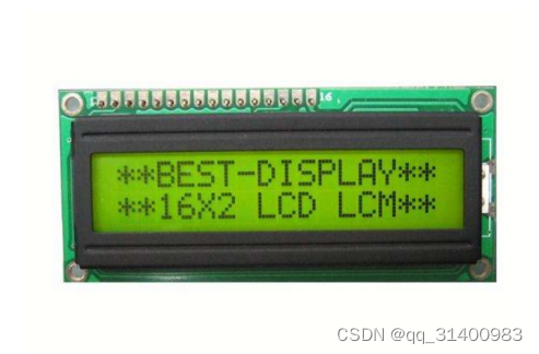
LCD1602显示屏
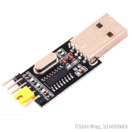
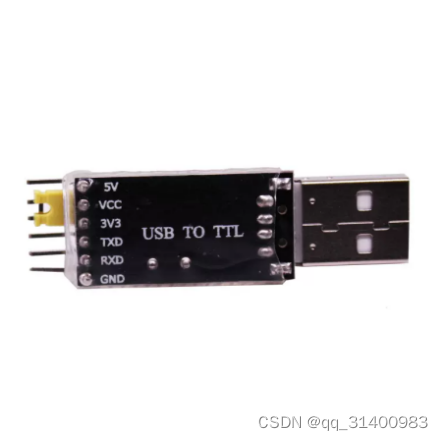
USB转TTL-CH340模块
2、软件:
GitHub血氧心率检测开源项目
三、安装CH340串口模块驱动
- 首先在网上下载CH340串口驱动程序,下载好以后,点击“SETUP.exe”开始安装。
- 在以下界面,点击“安装”控件。

3.安装完成后,点击“确定”。
4.在“我的电脑”--->“设备管理器”查看COM端口选项(记住这个COM口号,烧写程序时需选择该COM口)。
下载地址:ch340驱动下载_ch340驱动官方下载【绿色版】-华军软件园
四、烧写血氧检测软件
1. 下载开源软件
从GitHub下载开源软件,并解压缩。
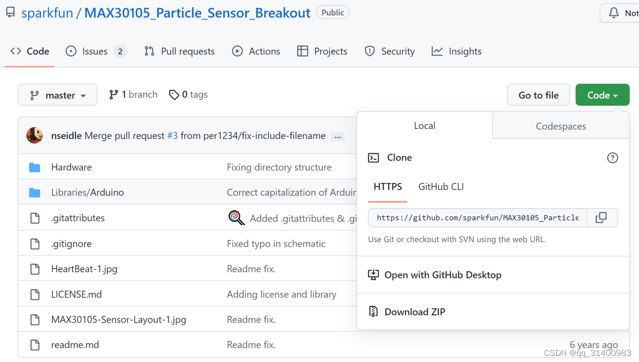
GitHub血氧心率检测开源项目
2. 连接CH340串口模块和Arduino Pro Mini
| Arduino Pro Mini | CH340 |
| RX | TX |
| TX | RX |
| GND | GND |
| VCC | 5V或3.3V(由Arduino Pro Mini具体型号确定) |
注意:如果你的USB转TTL模块有DTR引脚,将板子的DTR连接到USB转TTL模块上的DTR引脚,这样烧录时就不需要按Reset按钮。
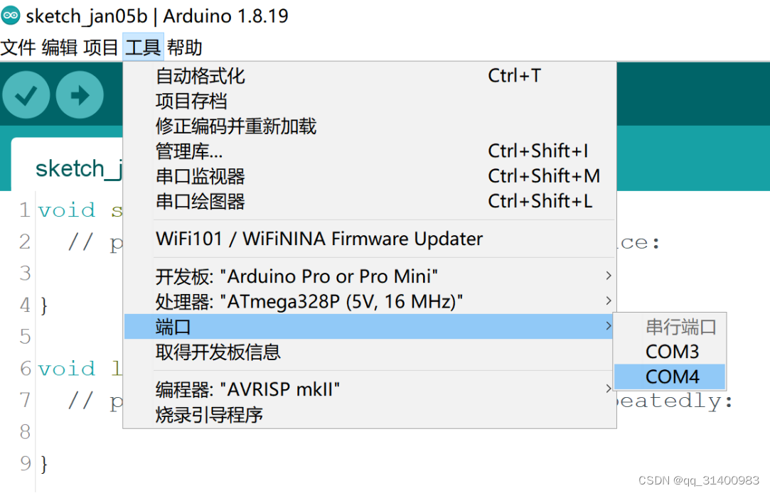
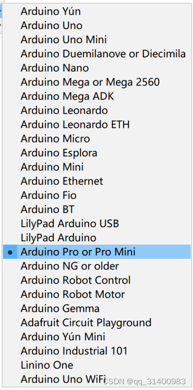
3. 配置Arduino IDE环境
启动Arduino IDE,选择之前CH340安装的端口号,将“开发板”型号设置为“Arduino Pro or Pro Mini”。
4. 打开下载好的开源程序并添加LCD显示部分代码
由于开源项目仅通过串口监测查看检测结果,因此需添加LCD显示输出代码,修改如下:
#include <Wire.h>
#include "MAX30105.h"
#include "spo2_algorithm.h"
#include <LiquidCrystal.h> //LCD

MAX30105 particleSensor;

#define MAX_BRIGHTNESS 255

#if defined(__AVR_ATmega328P__) || defined(__AVR_ATmega168__)
//Arduino Uno doesn't have enough SRAM to store 100 samples of IR led data and red led data in 32-bit format
//To solve this problem, 16-bit MSB of the sampled data will be truncated. Samples become 16-bit data.
uint16_t irBuffer[100]; //infrared LED sensor data
uint16_t redBuffer[100];  //red LED sensor data
#else
uint32_t irBuffer[100]; //infrared LED sensor data
uint32_t redBuffer[100];  //red LED sensor data
#endif

int32_t bufferLength; //data length
int32_t spo2; //SPO2 value
int8_t validSPO2; //indicator to show if the SPO2 calculation is valid
int32_t heartRate; //heart rate value
int8_t validHeartRate; //indicator to show if the heart rate calculation is valid

//byte pulseLED = 11; //Must be on PWM pin
byte readLED = 13; //Blinks with each data read

LiquidCrystal lcd(12,11,5,4,3,2);//init LCD

void setup()
{
  Serial.begin(115200); // initialize serial communication at 115200 bits per second:

  lcd.begin(16,2);//Set line and row
  //lcd.print(" %SpO2    PRbpm");//Print SpO2 and PRbpm Title

  //pinMode(pulseLED, OUTPUT);
  pinMode(readLED, OUTPUT);

  // Initialize sensor
  if (!particleSensor.begin(Wire, I2C_SPEED_FAST)) //Use default I2C port, 400kHz speed
  {
    Serial.println(F("MAX30105 was not found. Please check wiring/power."));
    while (1);
  }

  //Serial.println(F("Attach sensor to finger with rubber band. Press any key to start conversion"));
  //while (Serial.available() == 0) ; //wait until user presses a key
  Serial.read();

  byte ledBrightness = 60; //Options: 0=Off to 255=50mA
  byte sampleAverage = 4; //Options: 1, 2, 4, 8, 16, 32
  byte ledMode = 2; //Options: 1 = Red only, 2 = Red + IR, 3 = Red + IR + Green
  byte sampleRate = 100; //Options: 50, 100, 200, 400, 800, 1000, 1600, 3200
  int pulseWidth = 411; //Options: 69, 118, 215, 411
  int adcRange = 4096; //Options: 2048, 4096, 8192, 16384

  particleSensor.setup(ledBrightness, sampleAverage, ledMode, sampleRate, pulseWidth, adcRange); //Configure sensor with these settings
}

void loop()
{
  bufferLength = 100; //buffer length of 100 stores 4 seconds of samples running at 25sps

  //read the first 100 samples, and determine the signal range
  for (byte i = 0 ; i < bufferLength ; i++)
  {
    while (particleSensor.available() == false) //do we have new data?
      particleSensor.check(); //Check the sensor for new data

    redBuffer[i] = particleSensor.getRed();
    irBuffer[i] = particleSensor.getIR();
    particleSensor.nextSample(); //We're finished with this sample so move to next sample

    Serial.print(F("red="));
    Serial.print(redBuffer[i], DEC);
    Serial.print(F(", ir="));
    Serial.println(irBuffer[i], DEC);

    lcd.clear();
    lcd.setCursor(0,0);
    lcd.print("Push your finger");
    lcd.setCursor(0,1);
    lcd.print("on the sensor");
  }

  //calculate heart rate and SpO2 after first 100 samples (first 4 seconds of samples)
  maxim_heart_rate_and_oxygen_saturation(irBuffer, bufferLength, redBuffer, &spo2, &validSPO2, &heartRate, &validHeartRate);

  //Continuously taking samples from MAX30102.  Heart rate and SpO2 are calculated every 1 second
  while (1)
  {
    //dumping the first 25 sets of samples in the memory and shift the last 75 sets of samples to the top
    for (byte i = 25; i < 100; i++)
    {
      redBuffer[i - 25] = redBuffer[i];
      irBuffer[i - 25] = irBuffer[i];
    }

    //take 25 sets of samples before calculating the heart rate.
    for (byte i = 75; i < 100; i++)
    {
      while (particleSensor.available() == false) //do we have new data?
        particleSensor.check(); //Check the sensor for new data

      digitalWrite(readLED, !digitalRead(readLED)); //Blink onboard LED with every data read

      redBuffer[i] = particleSensor.getRed();
      irBuffer[i] = particleSensor.getIR();
      particleSensor.nextSample(); //We're finished with this sample so move to next sample

      //send samples and calculation result to terminal program through UART
      Serial.print(F("red="));
      Serial.print(redBuffer[i], DEC);
      Serial.print(F(", ir="));
      Serial.print(irBuffer[i], DEC);

      Serial.print(F(", HR="));
      Serial.print(heartRate, DEC);

      Serial.print(F(", HRvalid="));
      Serial.print(validHeartRate, DEC);

      Serial.print(F(", SPO2="));
      Serial.print(spo2, DEC);

      Serial.print(F(", SPO2Valid="));
      Serial.println(validSPO2, DEC);

      lcd.clear();

      lcd.setCursor(2,0);
      lcd.print("%SpO2:");
      lcd.setCursor(8,0);
      lcd.print(spo2);

      lcd.setCursor(2,1);
      lcd.print("PRbpm:");
      lcd.setCursor(8,1);
      lcd.print(heartRate);

    }

    //After gathering 25 new samples recalculate HR and SP02
    maxim_heart_rate_and_oxygen_saturation(irBuffer, bufferLength, redBuffer, &spo2, &validSPO2, &heartRate, &validHeartRate);
  }
}
5. 烧写代码
程序编译没有问题的话,就可以开始上传,但要注意,如USB转TTL模块没有DTR引脚,需要你在IDE开始上传的一瞬间(差不多就行)按下板子上的Reset按钮,这样才能上传成功。
五、连接电路
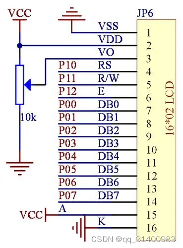
根据LCD1602的引脚定义如上图,和Arduino Pro mini的连接方法如下:
LCD VSS 接地
LCD VDD 接5V电源
LCD VL 用于调节对比度,通过电位器再接地。
LCD RS pin 链接数字口 pin12
LCD R/W pin 接地
LCD Enable pin 链接数字口 pin11
LCD D4 pin 链接数字口 pin5
LCD D5 pin 链接数字口 pin4
LCD D6 pin 链接数字口 pin3
LCD D7 pin 链接数字口 pin2
LCD BLA 光源正极
LCD BLK 光源负极
MAX30102和Arduino Pro mini的连接方法如下:
| MAX30102 | Arduino Pro mini |
| GND | GND |
| SCL | A5 |
| SDA | A4 |
| VIN | 5V电源 |


 2万+
2万+


 被折叠的 条评论
为什么被折叠?
被折叠的 条评论
为什么被折叠?
 到【灌水乐园】发言


