


本部分主要介绍基于GPU的相机视锥体可见性剔除模型以及根据模型距摄像机距离处理择选模型LOD的方法。在本部分中计算着色器用于修改存储在间接绘制命令缓冲区中的绘制命令,以切换模型可见性并根据摄像机距离选择其详细程度,而无需在CPU上进行任何计算并与CPU同步数据渲染。

一、理论
遮挡剔除(Occlusion Culling)
遮挡剔除是一种渲染优化技术,它使得摄像机视线范围内但又看不见的物体不被渲染。
在vulkan中,摄像机视线范围以内的物体会被进行渲染。这就可能出现一个问题:有些物体(游戏物体)在视线范围以内,但是摄像机看不见他们(或者说他们被别的物体挡住了),而这些物体依然需要被渲染。那这种渲染其实是无意义的。
而遮挡剔除就是剔除掉这些物体,不对这些物体进行渲染。从而降低了渲染上的开销。
但这其实是有弊端的,因为这使得CPU在做数据准备的时候,需要判断哪些(物体的)顶点需要被处理,哪些不需要。因此遮挡剔除技术实际上是增加了CPU的开销,从而来降低GPU开销的一种技术。
所以,对于游戏物体密集度很高的场景,遮挡剔除是十分适合的。但对于密集度不是那么高的场景,遮挡剔除反而会浪费性能。
LOD(Levels Of Detail 多细节层次)
LOD也是一种渲染优化技术,它使得摄像机视线范围内靠近的物体显示精模,远离的物体显示简模。
对于一个精模来说,当他离摄像机比较远的时候(依旧在视线范围内),视窗呈现出来的精致效果其实不明显的。在这样的一种情况下,GPU还要对这个精模进行渲染,实际上是没有太大意义的。
而LOD技术就是让一个模型,当他靠近摄像机的时候显示它的精模,让它远离摄像机的时候显示它的简模。从而降低渲染上的开销。
但LOD也是有弊端的,那就是LOD技术,使得开发人员需要同时准备物体的精模、中模、简模…(甚至更多),这使得这种技术十分消耗内存。
所以,对于一个存在精模,且精模会与摄像机的位置会产生变化的场景,适合采用LOD(本部分将使用一个具有lod的模型来处理)。
二、vulkan实现
2.1 场景数据定义
首先我们来看一下场景中需要自定义的一些数据结构:
	//场景中物体的总数(^3)
	#define OBJECT_COUNT 16
	#define MAX_LOD_LEVEL 5
	//仅显示视锥体中的模型
	bool fixedFrustum = false;

	// 每个实例数据块
	struct InstanceData {
		glm::vec3 pos;
		float scale;
	};

	// 包含实例数据
	vks::Buffer instanceBuffer;
	// 包含间接绘制命令
	vks::Buffer indirectCommandsBuffer;
	vks::Buffer indirectDrawCountBuffer;

	// 间接绘制统计数据(通过计算着色器更新)
	struct {
		uint32_t drawCount;						// 发行的间接支取点数的总数
		uint32_t lodCount[MAX_LOD_LEVEL + 1];	// 统计每个LOD级别的绘制数量(由计算着色器编写)
	} indirectStats;

	// 存储包含每个对象的索引偏移量和实例计数的间接绘制命令
	std::vector<VkDrawIndexedIndirectCommand> indirectCommands;
	//UBO
	struct {
		glm::mat4 projection;
		glm::mat4 modelview;
		glm::vec4 cameraPos;
		glm::vec4 frustumPlanes[6]; //视锥体平面信息
	} uboScene;
	//场景uniform数据
	struct {
		vks::Buffer scene;
	} uniformData;

	struct {
		VkPipeline plants;
	} pipelines;

	VkPipelineLayout pipelineLayout;
	VkDescriptorSet descriptorSet;
	VkDescriptorSetLayout descriptorSetLayout;

	// 计算管线部分的资源
	struct {
		vks::Buffer lodLevelsBuffers;				// 包含不同lod级别的索引起始和计数
		VkQueue queue;								// 用于计算命令的单独队列(队列族可能与用于图形的队列不同)
		VkCommandPool commandPool;					// 使用单独的命令池(队列族可能与用于图形的不同)
		VkCommandBuffer commandBuffer;				// 存储调度命令和屏障的命令缓冲区
		VkFence fence;								// 同步栅栏以避免在仍在使用时重写计算CB
		VkSemaphore semaphore;						// 用作图形提交的等待信号量
		VkDescriptorSetLayout descriptorSetLayout;	// 计算着色器绑定布局
		VkDescriptorSet descriptorSet;				// 计算着色器绑定
		VkPipelineLayout pipelineLayout;			// 计算管道的布局
		VkPipeline pipeline;						// 计算管道更新粒子位置
	} compute;

	// 视锥体剔除不可见的对象
	vks::Frustum frustum;
	//场景模型数量(objectCount立方 )
	uint32_t objectCount = 0;
其中,我们新定义立刻一个视锥体类来处理视锥体相关操作:
#include <array>
#include <math.h>
#include <glm/glm.hpp>

namespace vks
{
	class Frustum
	{
	public:
		enum side { LEFT = 0, RIGHT = 1, TOP = 2, BOTTOM = 3, BACK = 4, FRONT = 5 };
		std::array<glm::vec4, 6> planes;
		//更新六面
		void update(glm::mat4 matrix)
		{
			planes[LEFT].x = matrix[0].w + matrix[0].x;
			planes[LEFT].y = matrix[1].w + matrix[1].x;
			planes[LEFT].z = matrix[2].w + matrix[2].x;
			planes[LEFT].w = matrix[3].w + matrix[3].x;

			planes[RIGHT].x = matrix[0].w - matrix[0].x;
			planes[RIGHT].y = matrix[1].w - matrix[1].x;
			planes[RIGHT].z = matrix[2].w - matrix[2].x;
			planes[RIGHT].w = matrix[3].w - matrix[3].x;

			planes[TOP].x = matrix[0].w - matrix[0].y;
			planes[TOP].y = matrix[1].w - matrix[1].y;
			planes[TOP].z = matrix[2].w - matrix[2].y;
			planes[TOP].w = matrix[3].w - matrix[3].y;

			planes[BOTTOM].x = matrix[0].w + matrix[0].y;
			planes[BOTTOM].y = matrix[1].w + matrix[1].y;
			planes[BOTTOM].z = matrix[2].w + matrix[2].y;
			planes[BOTTOM].w = matrix[3].w + matrix[3].y;

			planes[BACK].x = matrix[0].w + matrix[0].z;
			planes[BACK].y = matrix[1].w + matrix[1].z;
			planes[BACK].z = matrix[2].w + matrix[2].z;
			planes[BACK].w = matrix[3].w + matrix[3].z;

			planes[FRONT].x = matrix[0].w - matrix[0].z;
			planes[FRONT].y = matrix[1].w - matrix[1].z;
			planes[FRONT].z = matrix[2].w - matrix[2].z;
			planes[FRONT].w = matrix[3].w - matrix[3].z;

			for (auto i = 0; i < planes.size(); i++)
			{
				float length = sqrtf(planes[i].x * planes[i].x + planes[i].y * planes[i].y + planes[i].z * planes[i].z);
				planes[i] /= length;
			}
		}
		//检查范围
		bool checkSphere(glm::vec3 pos, float radius)
		{
			for (auto i = 0; i < planes.size(); i++)
			{
				if ((planes[i].x * pos.x) + (planes[i].y * pos.y) + (planes[i].z * pos.z) + planes[i].w <= -radius)
				{
					return false;
				}
			}
			return true;
		}
	};
}
2.2 顶点输入属性及图形管线
加载完具有LOD数据的模型后,我们需要创建setupVertexDescriptions来设置定点输入属性:
	void setupVertexDescriptions()
	{
		vertices.bindingDescriptions.resize(2);

		// Binding 0:  每个顶点
		vertices.bindingDescriptions[0] =
			vks::initializers::vertexInputBindingDescription(VERTEX_BUFFER_BIND_ID, vertexLayout.stride(), VK_VERTEX_INPUT_RATE_VERTEX);

		// Binding 1:  每个实例
		vertices.bindingDescriptions[1] =
			vks::initializers::vertexInputBindingDescription(INSTANCE_BUFFER_BIND_ID, sizeof(InstanceData), VK_VERTEX_INPUT_RATE_INSTANCE);

		// 属性描述
		// 描述内存布局和着色器位置
		vertices.attributeDescriptions.clear();

		//  每个顶点都具备的属性
		// Location 0 : Position
		vertices.attributeDescriptions.push_back(
			vks::initializers::vertexInputAttributeDescription(
				VERTEX_BUFFER_BIND_ID,
				0,
				VK_FORMAT_R32G32B32_SFLOAT,
				0)
			);
		// Location 1 : Normal
		vertices.attributeDescriptions.push_back(
			vks::initializers::vertexInputAttributeDescription(
				VERTEX_BUFFER_BIND_ID,
				1,
				VK_FORMAT_R32G32B32_SFLOAT,
				sizeof(float) * 3)
			);
		// Location 2 : Color
		vertices.attributeDescriptions.push_back(
			vks::initializers::vertexInputAttributeDescription(
				VERTEX_BUFFER_BIND_ID,
				2,
				VK_FORMAT_R32G32B32_SFLOAT,
				sizeof(float) * 6)
			);

		// 实例属性
		// Location 4: Position
		vertices.attributeDescriptions.push_back(
			vks::initializers::vertexInputAttributeDescription(
				INSTANCE_BUFFER_BIND_ID, 4, VK_FORMAT_R32G32B32_SFLOAT, offsetof(InstanceData, pos))
			);
		// Location 5: Scale
		vertices.attributeDescriptions.push_back(
			vks::initializers::vertexInputAttributeDescription(
				INSTANCE_BUFFER_BIND_ID, 5, VK_FORMAT_R32_SFLOAT, offsetof(InstanceData, scale))
			);

		vertices.inputState = vks::initializers::pipelineVertexInputStateCreateInfo();
		vertices.inputState.vertexBindingDescriptionCount = static_cast<uint32_t>(vertices.bindingDescriptions.size());
		vertices.inputState.pVertexBindingDescriptions = vertices.bindingDescriptions.data();
		vertices.inputState.vertexAttributeDescriptionCount = static_cast<uint32_t>(vertices.attributeDescriptions.size());
		vertices.inputState.pVertexAttributeDescriptions = vertices.attributeDescriptions.data();
	}
在创建图形管线的地方我们会将这些信息传送至VkGraphicsPipelineCreateInfo创建管线,而且其顶点和片元着色器很简单:
顶点着色器(indirectdraw.vert):
#version 450

// Vertex attributes
layout (location = 0) in vec4 inPos;
layout (location = 1) in vec3 inNormal;
layout (location = 2) in vec3 inColor;

// Instanced attributes
layout (location = 4) in vec3 instancePos;
layout (location = 5) in float instanceScale;

layout (binding = 0) uniform UBO
{
	mat4 projection;
	mat4 modelview;
} ubo;

layout (location = 0) out vec3 outNormal;
layout (location = 1) out vec3 outColor;
layout (location = 2) out vec3 outViewVec;
layout (location = 3) out vec3 outLightVec;

out gl_PerVertex
{
	vec4 gl_Position;
};

void main()
{
	outColor = inColor;

	outNormal = inNormal;
	//根据实例创建位置
	vec4 pos = vec4((inPos.xyz * instanceScale) + instancePos, 1.0);

	gl_Position = ubo.projection * ubo.modelview * pos;

	vec4 wPos = ubo.modelview * vec4(pos.xyz, 1.0);
	vec4 lPos = vec4(0.0, 10.0, 50.0, 1.0);
	outLightVec = lPos.xyz - pos.xyz;
	outViewVec = -pos.xyz;
}
片元着色器(indirectdraw.frag):
#version 450

layout (location = 0) in vec3 inNormal;
layout (location = 1) in vec3 inColor;
layout (location = 2) in vec3 inViewVec;
layout (location = 3) in vec3 inLightVec;

layout (location = 0) out vec4 outFragColor;

void main()
{
	vec3 N = normalize(inNormal);
	vec3 L = normalize(inLightVec);
	vec3 ambient = vec3(0.25);
	vec3 diffuse = vec3(max(dot(N, L), 0.0));
	outFragColor = vec4((ambient + diffuse) * inColor, 1.0);
}
2.3 缓冲区数据填充
介绍完图形着色器后顶点输入及着色器后,我们来填充缓冲区数据,首先创建一个prepareBuffers函数:
	void prepareBuffers()
	{
		objectCount = OBJECT_COUNT * OBJECT_COUNT * OBJECT_COUNT;

		vks::Buffer stagingBuffer;

		std::vector<InstanceData> instanceData(objectCount);
		indirectCommands.resize(objectCount);

		//  间接画命令
		for (uint32_t x = 0; x < OBJECT_COUNT; x++)
		{
			for (uint32_t y = 0; y < OBJECT_COUNT; y++)
			{
				for (uint32_t z = 0; z < OBJECT_COUNT; z++)
				{
					uint32_t index = x + y * OBJECT_COUNT + z * OBJECT_COUNT * OBJECT_COUNT;
					indirectCommands[index].instanceCount = 1;
					indirectCommands[index].firstInstance = index;
					// firstIndex和indexCount是由计算着色器编写的
				}
			}
		}

		indirectStats.drawCount = static_cast<uint32_t>(indirectCommands.size());

		VK_CHECK_RESULT(vulkanDevice->createBuffer(
			VK_BUFFER_USAGE_TRANSFER_SRC_BIT,
			VK_MEMORY_PROPERTY_HOST_VISIBLE_BIT | VK_MEMORY_PROPERTY_HOST_COHERENT_BIT,
			&stagingBuffer,
			indirectCommands.size() * sizeof(VkDrawIndexedIndirectCommand),
			indirectCommands.data()));

		VK_CHECK_RESULT(vulkanDevice->createBuffer(
			VK_BUFFER_USAGE_INDIRECT_BUFFER_BIT | VK_BUFFER_USAGE_STORAGE_BUFFER_BIT | VK_BUFFER_USAGE_TRANSFER_DST_BIT,
			VK_MEMORY_PROPERTY_DEVICE_LOCAL_BIT,
			&indirectCommandsBuffer,
			stagingBuffer.size));

		vulkanDevice->copyBuffer(&stagingBuffer, &indirectCommandsBuffer, queue);

		stagingBuffer.destroy();

		VK_CHECK_RESULT(vulkanDevice->createBuffer(
			VK_BUFFER_USAGE_STORAGE_BUFFER_BIT | VK_BUFFER_USAGE_TRANSFER_SRC_BIT,
			VK_MEMORY_PROPERTY_HOST_VISIBLE_BIT | VK_MEMORY_PROPERTY_HOST_COHERENT_BIT,
			&indirectDrawCountBuffer,
			sizeof(indirectStats)));

		// 主机访问映射
		VK_CHECK_RESULT(indirectDrawCountBuffer.map());

		// Instance data 实例数据
		for (uint32_t x = 0; x < OBJECT_COUNT; x++)
		{
			for (uint32_t y = 0; y < OBJECT_COUNT; y++)
			{
				for (uint32_t z = 0; z < OBJECT_COUNT; z++)
				{
					uint32_t index = x + y * OBJECT_COUNT + z * OBJECT_COUNT * OBJECT_COUNT;
					instanceData[index].pos = glm::vec3((float)x, (float)y, (float)z) - glm::vec3((float)OBJECT_COUNT / 2.0f);
					instanceData[index].scale = 2.0f;
				}
			}
		}

		VK_CHECK_RESULT(vulkanDevice->createBuffer(
			VK_BUFFER_USAGE_TRANSFER_SRC_BIT,
			VK_MEMORY_PROPERTY_HOST_VISIBLE_BIT | VK_MEMORY_PROPERTY_HOST_COHERENT_BIT,
			&stagingBuffer,
			instanceData.size() * sizeof(InstanceData),
			instanceData.data()));

		VK_CHECK_RESULT(vulkanDevice->createBuffer(
			VK_BUFFER_USAGE_VERTEX_BUFFER_BIT | VK_BUFFER_USAGE_STORAGE_BUFFER_BIT | VK_BUFFER_USAGE_TRANSFER_DST_BIT,
			VK_MEMORY_PROPERTY_DEVICE_LOCAL_BIT,
			&instanceBuffer,
			stagingBuffer.size));

		vulkanDevice->copyBuffer(&stagingBuffer, &instanceBuffer, queue);

		stagingBuffer.destroy();

		// 包含索引偏移量和lod计数的着色器存储缓冲区
		struct LOD
		{
			uint32_t firstIndex;
			uint32_t indexCount;
			float distance;
			float _pad0;
		};
		std::vector<LOD> LODLevels;
		uint32_t n = 0;
		for (auto modelPart : models.lodObject.parts)
		{
			LOD lod;
			lod.firstIndex = modelPart.indexBase;			// 这个LOD的第一个索引
			lod.indexCount = modelPart.indexCount;			// 这个LOD的索引计数
			lod.distance = 5.0f + n * 5.0f;					// 这个LOD的起始距离(到观察相机位置),计算着色器中判断模型LOD用
			n++;
			LODLevels.push_back(lod);
		}

		VK_CHECK_RESULT(vulkanDevice->createBuffer(
			VK_BUFFER_USAGE_TRANSFER_SRC_BIT,
			VK_MEMORY_PROPERTY_HOST_VISIBLE_BIT | VK_MEMORY_PROPERTY_HOST_COHERENT_BIT,
			&stagingBuffer,
			LODLevels.size() * sizeof(LOD),
			LODLevels.data()));

		VK_CHECK_RESULT(vulkanDevice->createBuffer(
			VK_BUFFER_USAGE_STORAGE_BUFFER_BIT | VK_BUFFER_USAGE_TRANSFER_DST_BIT,
			VK_MEMORY_PROPERTY_DEVICE_LOCAL_BIT,
			&compute.lodLevelsBuffers,
			stagingBuffer.size));

		vulkanDevice->copyBuffer(&stagingBuffer, &compute.lodLevelsBuffers, queue);

		stagingBuffer.destroy();

		// 场景缓冲区
		VK_CHECK_RESULT(vulkanDevice->createBuffer(
			VK_BUFFER_USAGE_UNIFORM_BUFFER_BIT,
			VK_MEMORY_PROPERTY_HOST_VISIBLE_BIT | VK_MEMORY_PROPERTY_HOST_COHERENT_BIT,
			&uniformData.scene,
			sizeof(uboScene)));

		VK_CHECK_RESULT(uniformData.scene.map());

		updateUniformBuffer(true);
	}
其中updateUniformBuffer函数中来实时更新场景中数据:
void updateUniformBuffer(bool viewChanged)
	{
		if (viewChanged)
		{
			uboScene.projection = camera.matrices.perspective;
			uboScene.modelview = camera.matrices.view;
			//通过不更新视锥体数据固定视锥从而渲染固定场景的模型
			if (!fixedFrustum)
			{
				uboScene.cameraPos = glm::vec4(camera.position, 1.0f) * -1.0f;
				frustum.update(uboScene.projection * uboScene.modelview);
				memcpy(uboScene.frustumPlanes, frustum.planes.data(), sizeof(glm::vec4) * 6);
			}
		}

		memcpy(uniformData.scene.mapped, &uboScene, sizeof(uboScene));
	}
之后常规的创建描述符布局、2.2的管线创建相关、描述符池、描述符集等操作,balabala…
2.4 计算管线创建与运行
现在我们的场景数据都已创建我们,我们接下来需要进行计算管线与命令创建:
	void prepareCompute()
	{
		// 获取具有计算能力的设备队列
		vkGetDeviceQueue(device, vulkanDevice->queueFamilyIndices.compute, 0, &compute.queue);

		//创建计算管道
		//计算管道与图形管道创建时是分开的,即使它们使用相同的队列(家族索引)
		std::vector<VkDescriptorSetLayoutBinding> setLayoutBindings = {
			// Binding 0: 实例输入数据缓冲区
			vks::initializers::descriptorSetLayoutBinding(
				VK_DESCRIPTOR_TYPE_STORAGE_BUFFER,
				VK_SHADER_STAGE_COMPUTE_BIT,
				0),
			// Binding 1: 绑定1:间接绘制命令输出缓冲区(输入)
			vks::initializers::descriptorSetLayoutBinding(
				VK_DESCRIPTOR_TYPE_STORAGE_BUFFER,
				VK_SHADER_STAGE_COMPUTE_BIT,
				1),
			// Binding 2: 绑定2:统一缓冲区与全局矩阵(输入)
			vks::initializers::descriptorSetLayoutBinding(
				VK_DESCRIPTOR_TYPE_UNIFORM_BUFFER,
				VK_SHADER_STAGE_COMPUTE_BIT,
				2),
			// Binding 3: 间接draw stats(输出)
			vks::initializers::descriptorSetLayoutBinding(
				VK_DESCRIPTOR_TYPE_STORAGE_BUFFER,
				VK_SHADER_STAGE_COMPUTE_BIT,
				3),
			// Binding 4: LOD信息(输入)
			vks::initializers::descriptorSetLayoutBinding(
				VK_DESCRIPTOR_TYPE_STORAGE_BUFFER,
				VK_SHADER_STAGE_COMPUTE_BIT,
				4),
		};

		VkDescriptorSetLayoutCreateInfo descriptorLayout =
			vks::initializers::descriptorSetLayoutCreateInfo(
				setLayoutBindings.data(),
				static_cast<uint32_t>(setLayoutBindings.size()));

		VK_CHECK_RESULT(vkCreateDescriptorSetLayout(device, &descriptorLayout, nullptr, &compute.descriptorSetLayout));

		VkPipelineLayoutCreateInfo pPipelineLayoutCreateInfo =
			vks::initializers::pipelineLayoutCreateInfo(
				&compute.descriptorSetLayout,
				1);

		VK_CHECK_RESULT(vkCreatePipelineLayout(device, &pPipelineLayoutCreateInfo, nullptr, &compute.pipelineLayout));

		VkDescriptorSetAllocateInfo allocInfo =
			vks::initializers::descriptorSetAllocateInfo(
				descriptorPool,
				&compute.descriptorSetLayout,
				1);

		VK_CHECK_RESULT(vkAllocateDescriptorSets(device, &allocInfo, &compute.descriptorSet));

		std::vector<VkWriteDescriptorSet> computeWriteDescriptorSets =
		{
			// Binding 0: 实例输入数据缓冲区
			vks::initializers::writeDescriptorSet(
				compute.descriptorSet,
				VK_DESCRIPTOR_TYPE_STORAGE_BUFFER,
				0,
				&instanceBuffer.descriptor),
			// Binding 1: 间接绘制命令输出缓冲区
			vks::initializers::writeDescriptorSet(
				compute.descriptorSet,
				VK_DESCRIPTOR_TYPE_STORAGE_BUFFER,
				1,
				&indirectCommandsBuffer.descriptor),
			// Binding 2: 具有全局矩阵的统一缓冲区
			vks::initializers::writeDescriptorSet(
				compute.descriptorSet,
				VK_DESCRIPTOR_TYPE_UNIFORM_BUFFER,
				2,
				&uniformData.scene.descriptor),
			// Binding 3: 原子计数器(用着色器编写)
			vks::initializers::writeDescriptorSet(
				compute.descriptorSet,
				VK_DESCRIPTOR_TYPE_STORAGE_BUFFER,
				3,
				&indirectDrawCountBuffer.descriptor),
			// Binding 4: LOD信息
			vks::initializers::writeDescriptorSet(
				compute.descriptorSet,
				VK_DESCRIPTOR_TYPE_STORAGE_BUFFER,
				4,
				&compute.lodLevelsBuffers.descriptor)
		};

		vkUpdateDescriptorSets(device, static_cast<uint32_t>(computeWriteDescriptorSets.size()), computeWriteDescriptorSets.data(), 0, NULL);

		// 创建管道
		VkComputePipelineCreateInfo computePipelineCreateInfo = vks::initializers::computePipelineCreateInfo(compute.pipelineLayout, 0);
		computePipelineCreateInfo.stage = loadShader(getAssetPath() + "shaders/computecullandlod/cull.comp.spv", VK_SHADER_STAGE_COMPUTE_BIT);

		//使用专门化常量传递最大值。详细程度(由编号决定)网格)
		VkSpecializationMapEntry specializationEntry{};
		specializationEntry.constantID = 0;
		specializationEntry.offset = 0;
		specializationEntry.size = sizeof(uint32_t);

		uint32_t specializationData = static_cast<uint32_t>(models.lodObject.parts.size()) - 1;

		VkSpecializationInfo specializationInfo;
		specializationInfo.mapEntryCount = 1;
		specializationInfo.pMapEntries = &specializationEntry;
		specializationInfo.dataSize = sizeof(specializationData);
		specializationInfo.pData = &specializationData;

		computePipelineCreateInfo.stage.pSpecializationInfo = &specializationInfo;

		VK_CHECK_RESULT(vkCreateComputePipelines(device, pipelineCache, 1, &computePipelineCreateInfo, nullptr, &compute.pipeline));

		//作为计算队列家族的单独命令池可能与图形不同
		VkCommandPoolCreateInfo cmdPoolInfo = {};
		cmdPoolInfo.sType = VK_STRUCTURE_TYPE_COMMAND_POOL_CREATE_INFO;
		cmdPoolInfo.queueFamilyIndex = vulkanDevice->queueFamilyIndices.compute;
		cmdPoolInfo.flags = VK_COMMAND_POOL_CREATE_RESET_COMMAND_BUFFER_BIT;
		VK_CHECK_RESULT(vkCreateCommandPool(device, &cmdPoolInfo, nullptr, &compute.commandPool));

		// 为计算操作创建一个命令缓冲区
		VkCommandBufferAllocateInfo cmdBufAllocateInfo =
			vks::initializers::commandBufferAllocateInfo(
				compute.commandPool,
				VK_COMMAND_BUFFER_LEVEL_PRIMARY,
				1);

		VK_CHECK_RESULT(vkAllocateCommandBuffers(device, &cmdBufAllocateInfo, &compute.commandBuffer));

		// 栅栏用于计算CB同步
		VkFenceCreateInfo fenceCreateInfo = vks::initializers::fenceCreateInfo(VK_FENCE_CREATE_SIGNALED_BIT);
		VK_CHECK_RESULT(vkCreateFence(device, &fenceCreateInfo, nullptr, &compute.fence));

		VkSemaphoreCreateInfo semaphoreCreateInfo = vks::initializers::semaphoreCreateInfo();
		VK_CHECK_RESULT(vkCreateSemaphore(device, &semaphoreCreateInfo, nullptr, &compute.semaphore));

		// 构建包含计算分派命令的单个命令缓冲区
		buildComputeCommandBuffer();
	}
其中,我们需要构建包含计算分派命令的单个命令缓冲区,创建buildComputeCommandBuffer来执行此部分:
	void buildComputeCommandBuffer()
	{
		VkCommandBufferBeginInfo cmdBufInfo = vks::initializers::commandBufferBeginInfo();

		VK_CHECK_RESULT(vkBeginCommandBuffer(compute.commandBuffer, &cmdBufInfo));

		//添加内存屏障,以确保间接命令已经消耗之前,计算着色器更新他们
		VkBufferMemoryBarrier bufferBarrier = vks::initializers::bufferMemoryBarrier();
		bufferBarrier.buffer = indirectCommandsBuffer.buffer;
		bufferBarrier.size = indirectCommandsBuffer.descriptor.range;
		bufferBarrier.srcAccessMask = VK_ACCESS_INDIRECT_COMMAND_READ_BIT;
		bufferBarrier.dstAccessMask = VK_ACCESS_SHADER_WRITE_BIT;
		bufferBarrier.srcQueueFamilyIndex = vulkanDevice->queueFamilyIndices.graphics;
		bufferBarrier.dstQueueFamilyIndex = vulkanDevice->queueFamilyIndices.compute;

		vkCmdPipelineBarrier(
			compute.commandBuffer,
			VK_PIPELINE_STAGE_DRAW_INDIRECT_BIT,
			VK_PIPELINE_STAGE_COMPUTE_SHADER_BIT,
			VK_FLAGS_NONE,
			0, nullptr,
			1, &bufferBarrier,
			0, nullptr);

		vkCmdBindPipeline(compute.commandBuffer, VK_PIPELINE_BIND_POINT_COMPUTE, compute.pipeline);
		vkCmdBindDescriptorSets(compute.commandBuffer, VK_PIPELINE_BIND_POINT_COMPUTE, compute.pipelineLayout, 0, 1, &compute.descriptorSet, 0, 0);

		//分派计算作业
		//计算着色器将进行视锥剔除,并根据对象的可见性调整间接绘制调用。
		//它还决定使用的lod取决于距离观众。
		vkCmdDispatch(compute.commandBuffer, objectCount / 16, 1, 1);

		// 添加内存屏障,以确保计算着色器在使用之前已经完成间接命令缓冲区的写入
		bufferBarrier.srcAccessMask = VK_ACCESS_SHADER_WRITE_BIT;
		bufferBarrier.dstAccessMask = VK_ACCESS_INDIRECT_COMMAND_READ_BIT;
		bufferBarrier.buffer = indirectCommandsBuffer.buffer;
		bufferBarrier.size = indirectCommandsBuffer.descriptor.range;
		bufferBarrier.srcQueueFamilyIndex = vulkanDevice->queueFamilyIndices.compute;
		bufferBarrier.dstQueueFamilyIndex = vulkanDevice->queueFamilyIndices.graphics;

		vkCmdPipelineBarrier(
			compute.commandBuffer,
			VK_PIPELINE_STAGE_COMPUTE_SHADER_BIT,
			VK_PIPELINE_STAGE_DRAW_INDIRECT_BIT,
			VK_FLAGS_NONE,
			0, nullptr,
			1, &bufferBarrier,
			0, nullptr);

		vkEndCommandBuffer(compute.commandBuffer);
	}
接下来重点来了,计算着色器时如何实现的呢,直接上代码:
计算着色器(cull.comp):
#version 450

layout (constant_id = 0) const int MAX_LOD_LEVEL = 5;

struct InstanceData
{
	vec3 pos;
	float scale;
};

// Binding 0: 用于筛选的实例输入数据
layout (binding = 0, std140) buffer Instances
{
   InstanceData instances[ ];
};

// 与VkDrawIndexedIndirectCommand相同的布局
struct IndexedIndirectCommand
{
	uint indexCount;
	uint instanceCount;
	uint firstIndex;
	uint vertexOffset;
	uint firstInstance;
};

// 多画输出
layout (binding = 1, std430) writeonly buffer IndirectDraws
{
	IndexedIndirectCommand indirectDraws[ ];
};

// Binding 2: 统一块对象与矩阵
layout (binding = 2) uniform UBO
{
	mat4 projection;
	mat4 modelview;
	vec4 cameraPos;
	vec4 frustumPlanes[6];
} ubo;

// Binding 3: 间接绘制抽取属性
layout (binding = 3) buffer UBOOut
{
	uint drawCount;
	uint lodCount[MAX_LOD_LEVEL + 1];
} uboOut;

// Binding 4: 详细级别信息
struct LOD
{
	uint firstIndex;
	uint indexCount;
	float distance;
	float _pad0;
};
layout (binding = 4) readonly buffer LODs
{
	LOD lods[ ];
};

layout (local_size_x = 16) in;

bool frustumCheck(vec4 pos, float radius)
{
	// 根据视锥体平面判断是否在视锥体内
	for (int i = 0; i < 6; i++)
	{
		if (dot(pos, ubo.frustumPlanes[i]) + radius < 0.0)
		{
			return false;
		}
	}
	return true;
}

layout (local_size_x = 16) in;

void main()
{
	uint idx = gl_GlobalInvocationID.x + gl_GlobalInvocationID.y * gl_NumWorkGroups.x * gl_WorkGroupSize.x;

	//清除第一次调用时的统计数据
	if (idx == 0)
	{
		atomicExchange(uboOut.drawCount, 0);//在一帧开始时改变数据
		for (uint i = 0; i < MAX_LOD_LEVEL + 1; i++)
		{
			atomicExchange(uboOut.lodCount[i], 0);
		}
	}

	vec4 pos = vec4(instances[idx].pos.xyz, 1.0);

	// Check if object is within current viewing frustum
	//检查对象是否在当前查看截锥内
	if (frustumCheck(pos, 1.0))
	{
		indirectDraws[idx].instanceCount = 1;

		// 增加间接抽取点数
		atomicAdd(uboOut.drawCount, 1);//在一帧变化时数据+1

		//根据到相机的距离选择合适的LOD级别
		uint lodLevel = MAX_LOD_LEVEL;
		for (uint i = 0; i < MAX_LOD_LEVEL; i++)
		{
			if (distance(instances[idx].pos.xyz, ubo.cameraPos.xyz) < lods[i].distance)
			{
				lodLevel = i;
				break;
			}
		}
		indirectDraws[idx].firstIndex = lods[lodLevel].firstIndex;
		indirectDraws[idx].indexCount = lods[lodLevel].indexCount;
		// 更新统计数据
		atomicAdd(uboOut.lodCount[lodLevel], 1);
	}
	else
	{
		indirectDraws[idx].instanceCount = 0;
	}
}
2.5 图形管线绘制
在执行完计算管线后,首先我们需要创建常规的图形绘制命令及间接绘制命,然后我们需要的就是在根据剔除和LOD的数据来进行图形绘制:
void buildCommandBuffers()
	{
		VkCommandBufferBeginInfo cmdBufInfo = vks::initializers::commandBufferBeginInfo();

		VkClearValue clearValues[2];
		clearValues[0].color = { { 0.18f, 0.27f, 0.5f, 0.0f } };
		clearValues[1].depthStencil = { 1.0f, 0 };

		VkRenderPassBeginInfo renderPassBeginInfo = vks::initializers::renderPassBeginInfo();
		renderPassBeginInfo.renderPass = renderPass;
		renderPassBeginInfo.renderArea.extent.width = width;
		renderPassBeginInfo.renderArea.extent.height = height;
		renderPassBeginInfo.clearValueCount = 2;
		renderPassBeginInfo.pClearValues = clearValues;

		for (int32_t i = 0; i < drawCmdBuffers.size(); ++i)
		{
			// 设定目标帧缓冲器
			renderPassBeginInfo.framebuffer = frameBuffers[i];

			VK_CHECK_RESULT(vkBeginCommandBuffer(drawCmdBuffers[i], &cmdBufInfo));

			vkCmdBeginRenderPass(drawCmdBuffers[i], &renderPassBeginInfo, VK_SUBPASS_CONTENTS_INLINE);

			VkViewport viewport = vks::initializers::viewport((float)width, (float)height, 0.0f, 1.0f);
			vkCmdSetViewport(drawCmdBuffers[i], 0, 1, &viewport);

			VkRect2D scissor = vks::initializers::rect2D(width, height, 0, 0);
			vkCmdSetScissor(drawCmdBuffers[i], 0, 1, &scissor);

			VkDeviceSize offsets[1] = { 0 };
			vkCmdBindDescriptorSets(drawCmdBuffers[i], VK_PIPELINE_BIND_POINT_GRAPHICS, pipelineLayout, 0, 1, &descriptorSet, 0, NULL);

			// Mesh containing the LODs 包含lod的网格
			vkCmdBindPipeline(drawCmdBuffers[i], VK_PIPELINE_BIND_POINT_GRAPHICS, pipelines.plants);
			vkCmdBindVertexBuffers(drawCmdBuffers[i], VERTEX_BUFFER_BIND_ID, 1, &models.lodObject.vertices.buffer, offsets);
			vkCmdBindVertexBuffers(drawCmdBuffers[i], INSTANCE_BUFFER_BIND_ID, 1, &instanceBuffer.buffer, offsets);

			vkCmdBindIndexBuffer(drawCmdBuffers[i], models.lodObject.indices.buffer, 0, VK_INDEX_TYPE_UINT32);

			if (vulkanDevice->features.multiDrawIndirect)
			{
				vkCmdDrawIndexedIndirect(drawCmdBuffers[i], indirectCommandsBuffer.buffer, 0, indirectCommands.size(), sizeof(VkDrawIndexedIndirectCommand));
			}
			else
			{
				//如果多重绘制不可用,我们必须发出单独的绘制命令
				for (auto j = 0; j < indirectCommands.size(); j++)
				{
					vkCmdDrawIndexedIndirect(drawCmdBuffers[i], indirectCommandsBuffer.buffer, j * sizeof(VkDrawIndexedIndirectCommand), 1, sizeof(VkDrawIndexedIndirectCommand));
				}
			}

			drawUI(drawCmdBuffers[i]);

			vkCmdEndRenderPass(drawCmdBuffers[i]);

			VK_CHECK_RESULT(vkEndCommandBuffer(drawCmdBuffers[i]));
		}
	}
在绘制过程中,我们还必须在提交命令的时候注意对计算着色器中数据与图形管线中数据进行信号量及数据栅栏交互,以保证其数据顺序正确:
	void draw()
	{
		VulkanExampleBase::prepareFrame();

		// 提交计算着色器进行视锥剔除

		// 等待fence以确保计算缓冲区写操作已经完成
		vkWaitForFences(device, 1, &compute.fence, VK_TRUE, UINT64_MAX);
		vkResetFences(device, 1, &compute.fence);

		VkSubmitInfo computeSubmitInfo = vks::initializers::submitInfo();
		computeSubmitInfo.commandBufferCount = 1;
		computeSubmitInfo.pCommandBuffers = &compute.commandBuffer;
		computeSubmitInfo.signalSemaphoreCount = 1;
		computeSubmitInfo.pSignalSemaphores = &compute.semaphore;

		VK_CHECK_RESULT(vkQueueSubmit(compute.queue, 1, &computeSubmitInfo, VK_NULL_HANDLE));

		//提交图形命令缓冲区
		submitInfo.commandBufferCount = 1;
		submitInfo.pCommandBuffers = &drawCmdBuffers[currentBuffer];

		// 等待当前并计算信号量
		std::array<VkPipelineStageFlags,2> stageFlags = {
			VK_PIPELINE_STAGE_COLOR_ATTACHMENT_OUTPUT_BIT,
			VK_PIPELINE_STAGE_COMPUTE_SHADER_BIT,
		};
		std::array<VkSemaphore,2> waitSemaphores = {
			semaphores.presentComplete,						// 等待显示完成
			compute.semaphore								// 等待计算完成
		};

		submitInfo.pWaitSemaphores = waitSemaphores.data();
		submitInfo.waitSemaphoreCount = static_cast<uint32_t>(waitSemaphores.size());
		submitInfo.pWaitDstStageMask = stageFlags.data();

		// 提交到队列
		VK_CHECK_RESULT(vkQueueSubmit(queue, 1, &submitInfo, compute.fence));

		VulkanExampleBase::submitFrame();

		// 从计算中获得提取计数
		memcpy(&indirectStats, indirectDrawCountBuffer.mapped, sizeof(indirectStats));
	}
接下来,运行可见效果:
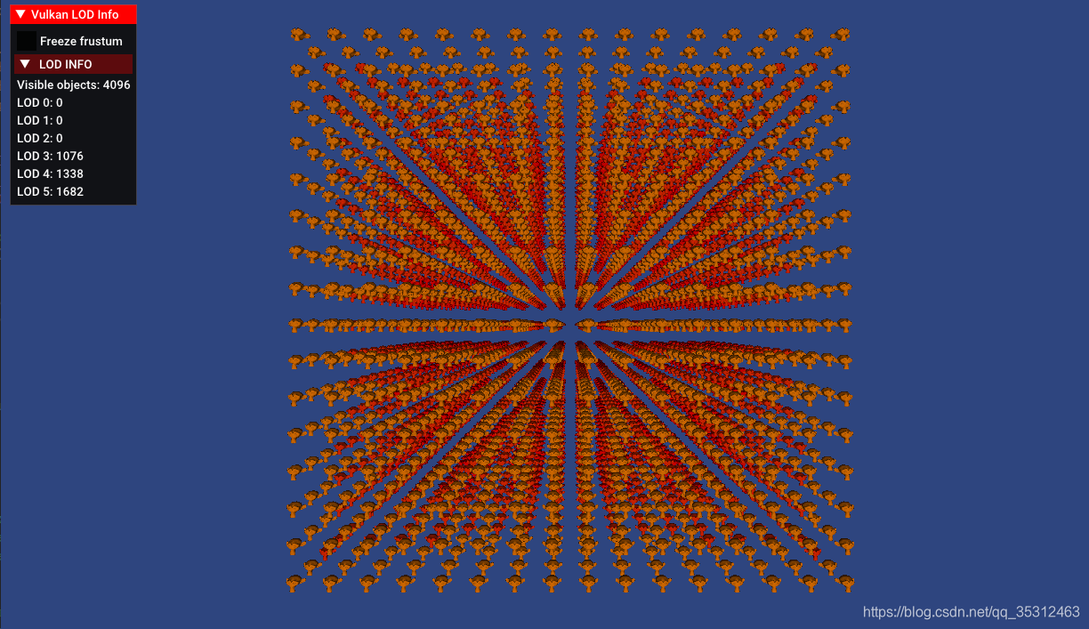
上图我们可以见到,在摄像机离模型较远时,对应的模型LOD为3/4/5等级,当我们将摄像机移动到近处我们可与看到下图:
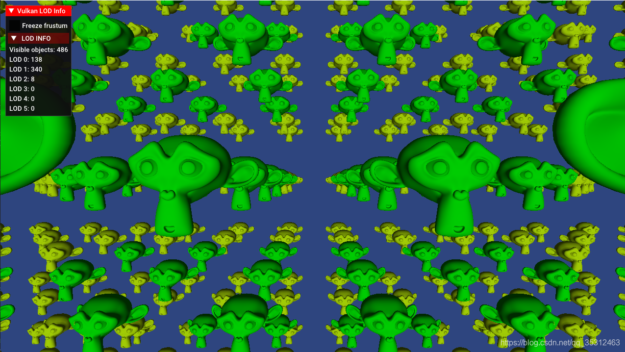
我们可以看到此时模型逐步变得精细,LOD为0/1/2级别,此时我们开启固定视锥体,移动相机视角可见下图:

此时我们可以看到,相机在固定视锥体时仅会看到其范围内的486个模型(共4096个模型)并进行了渲染,其余皆被剔除。


 1万+
1万+

 被折叠的 条评论
为什么被折叠?
被折叠的 条评论
为什么被折叠?
 到【灌水乐园】发言


