


文章目录
LoRa官方固件下载链接 LoRa固件源码 https://download.csdn.net/download/qq_36310253/11974427
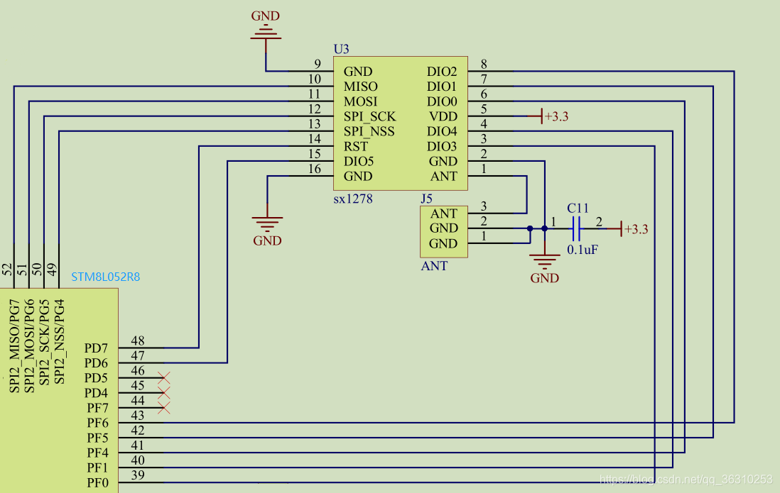
本次使用的是sx1278的LoRa芯片,MCU是STM8L052R8,sx1276、sx1277和sx1278只是中心频率有所不同,适用于不同的国家和地区,亚洲地区使用的是sx1278,不同芯片使用的官方固件库是一个,不同芯片区别如下

MCU和LoRa模块的连接原理图如下所示:
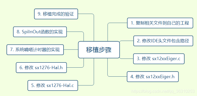
本文以IAR建立工程为例,讲述LoRa官方驱动的移植步骤,详细的移植步骤如下:

1. 建立STM8L052的工程
首先以官方固件库建立 STM8L052的工程,直至编译不出错或者可以点亮LED灯为止,证明自己建立的工程没有问题可以对MCU进行操作,本步骤的具体操作不再描述。
2. 拷贝与 sx1278 相关的文件到自己的工程文件夹下
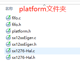
将官方固件包中的 platform 文件夹下的 fifo.c、sx1276-Hal.c、sx12xxEige.c 及相关的 .h 和 platform.h 文佳拷贝到自己的文件目录下,我这里定义的是platform文件夹,拷贝完成如下所示 。
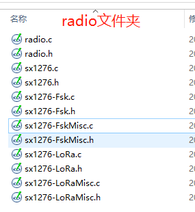
将官方固件包中的radio文件夹下的radio.c、sx1276-Lora.c、sx1276.c、sx1276-Fsk.c、sx1276-FskMisc.c、sx1276-LoraMisc.c及相关的.h文件拷贝到自己的文件目录下,我这里定义的是radio文件夹,拷贝完成如下图所示。
拷贝完成的工程目如下图所示:
3. 修改 platform.h文件
platform.h是平台相关头文件,里面定义了具体使用的是哪一个芯片型号,类似于STM32F1系列中的 stm32f1xx.h 文件,修改后的platform文件如下图所示。
38行定义了 PLATFORM 为 SX12xxEiger,然后在45-48行依据自己的LoRa芯片型号打开相应的宏定义(此宏在 radio.c 中的 RadioDriverInit 函数中使用,对应不同的芯片型号执行不同的初始化、发送和接收操作),本次使用的是sx1278,所示打开47行的宏定义。
因为本次使用的是sx1278芯片,所以要把54-61行的注释全部去掉,在60行定义了 sx12xxEiger.h 这个头文件的路径,需要依照自己实际工程的文件路径进行修改。
#ifndef __PLATFORM_H__
#define __PLATFORM_H__

#ifndef __GNUC__
#define inline
#endif
/*!
 * Platform definition
 */
#define Bleeper      3
#define SX1243ska    2
#define SX12xxEiger  1
#define SX12000DVK   0

/*!
 * Platform choice. Please uncoment the PLATFORM define and choose your platform
 * or add/change the PLATFORM definition on the compiler Defines option
 */
#define PLATFORM  SX12xxEiger

#if( PLATFORM == SX12xxEiger )
/*!
 * Radio choice. Please uncomment the wanted radio and comment the others
 * or add/change wanted radio definition on the compiler Defines option
 */
//#define USE_SX1232_RADIO
//#define USE_SX1272_RADIO
#define USE_SX1276_RADIO
//#define USE_SX1243_RADIO

/*!
 * Module choice. There are three existing module with the SX1276.
 * Please set the connected module to the value 1 and set the others to 0
 */
#ifdef USE_SX1276_RADIO
#define MODULE_SX1276RF1IAS  0
#define MODULE_SX1276RF1JAS  0
#define MODULE_SX1276RF1KAS  1
#endif

//  #include "sx12xxEiger/sx12xxEiger.h"
	#include "./sx12xxEiger.h"			// 2019-11-14 by lzj 修改sx12xxEiger.h的路径
    #define USE_UART         0

#elif( PLATFORM == SX12000DVK )
/*!
 * Radio choice. Please uncomment the wanted radio and comment the others
 * or add/change wanted radio definition on the compiler Defines option
 */
//#define USE_SX1232_RADIO
//#define USE_SX1272_RADIO
#define USE_SX1276_RADIO
//#define USE_SX1243_RADIO

	#include "sx1200dvk/sx1200dvk.h"

#elif( PLATFORM == SX1243ska )

#elif( PLATFORM == Bleeper )
    #define USE_SX1272_RADIO

    #include "bleeper/bleeper.h"
    #define USE_UART                                0

#else
    #error "Missing define: Platform (ie. SX12xxEiger)"
#endif

#endif // __PLATFORM_H__
4. 修改IAR工程头文件包含路径
修改头文件包含路径,将路径指定为自己建立的文件夹下
|-> options
	|-> c/c++ compiler
		|-> Preprocessor
			|-> 在Additional include direc中添加 $PROJ_DIR$/../radio
												$PROJ_DIR$/../sx12xxEiger
接下来就是和具体板子相关的修改,具体修改LoRa模块和板子连接的引脚部分内容的修改,具体的修改办法是编译工程找出错误的文件进行相应修改,详细修改过程如下:
5. 修改 sx12xxEiger.c
在 sx12xxEiger.c 文件中,主要定义了MCU和lora连接引脚的初始化即 BoardInit() 函数,因为通常在main函数的最开始对MCU及外设进行初始化,所以将该文件中的 BoardInit() 函数中的内容注释掉。因为该次实验没有用到USB所以将USB相关的内容注释掉,即27-43和50-63行,修改后的文件如下所示
/*
 * THE FOLLOWING FIRMWARE IS PROVIDED: (1) "AS IS" WITH NO WARRANTY; AND
 * (2)TO ENABLE ACCESS TO CODING INFORMATION TO GUIDE AND FACILITATE CUSTOMER.
 * CONSEQUENTLY, SEMTECH SHALL NOT BE HELD LIABLE FOR ANY DIRECT, INDIRECT OR
 * CONSEQUENTIAL DAMAGES WITH RESPECT TO ANY CLAIMS ARISING FROM THE CONTENT
 * OF SUCH FIRMWARE AND/OR THE USE MADE BY CUSTOMERS OF THE CODING INFORMATION
 * CONTAINED HEREIN IN CONNECTION WITH THEIR PRODUCTS.
 *
 * Copyright (C) SEMTECH S.A.
 */
/*!
 * \file       sx12xxEiger.c
 * \brief
 *
 * \version    1.0
 * \date       Nov 21 2012
 * \author     Miguel Luis
 */
#include <stdint.h>
//#include "spi.h"			// 2019-11-14 没用上,注释掉
//#include "i2c.h"			// 2019-11-14 没用上,注释掉
//#include "ioe.h"			// 2019-11-14 没用上,注释掉
//#include "led.h"			// 2019-11-14 没用上,注释掉
//#include "uart.h"			// 2019-11-14 没用上,注释掉
#include "sx12xxEiger.h"

// 2019-11-14 USB没用上,注释掉
//#if( defined( STM32F4XX ) || defined( STM32F2XX ) || defined( STM32F429_439xx ) )
//
//#include "usbd_cdc_core.h"
//#include "usbd_usr.h"
//#include "usbd_desc.h"
//
//#else
//
//#include "usb_regs.h"
//#include "usb_core.h"
//#include "usb_init.h"
//#include "usb_pwr.h"
//#include "usb_bsp.h"
//#include "usb_sil.h"
//
//#endif


// System tick (1ms)
volatile uint32_t TickCounter = 0;


// 2019-11-14 没用上,注释掉
//#if( defined( STM32F4XX ) || defined( STM32F2XX ) || defined( STM32F429_439xx ) )
//
//#ifdef USB_OTG_HS_INTERNAL_DMA_ENABLED
//  #if defined ( __ICCARM__ ) /*!< IAR Compiler */
//    #pragma data_alignment=4
//  #endif
//#endif /* USB_OTG_HS_INTERNAL_DMA_ENABLED */
//
//__ALIGN_BEGIN USB_OTG_CORE_HANDLE    USB_OTG_dev __ALIGN_END ;
//
//#else
//
//#endif


// BoardInit内容注释掉 板子初始化在main.c中完成
void BoardInit( void )
{
//    uint8_t i;
//
//    /* Setup SysTick Timer for 1 us interrupts ( not too often to save power ) */
//    if( SysTick_Config( SystemCoreClock / 1000 ) )
//    {
//        /* Capture error */
//        while (1);
//    }
//
//    // Initialize SPI
//    SpiInit( );
//
//    // Initialize I2C
//    I2cInit( );
//
//    // Initialize IO expander
//    IoeInit( );
//
//    // Initialize LED
//    for( i = 0; i < LED_NB; i++ )
//    {
//        LedInit( ( tLed )i );
//    }
//    IoePinOn( LED_1_PIN );
//    IoePinOn( LED_2_PIN );
//    IoePinOn( LED_3_PIN );
//
//#if( defined( STM32F4XX ) || defined( STM32F2XX ) || defined( STM32F429_439xx ) )
//
//    USBD_Init( &USB_OTG_dev,
//#ifdef USE_USB_OTG_HS
//               USB_OTG_HS_CORE_ID,
//#else
//               USB_OTG_FS_CORE_ID,
//#endif
//               &USR_desc,
//               &USBD_CDC_cb,
//               &USR_cb );
//#else
//        /* Configure the used GPIOs*/
//        GPIO_Configuration( );
//        /* Additional EXTI configuration (configure both edges) */
//        EXTI_Configuration( );
//
//        USB_Interrupts_Config( );
//        Set_USBClock( );
//        USB_Init( );
//#endif
}

void Delay ( uint32_t delay )
{
    // Wait delay ms
    uint32_t startTick = TickCounter;
    while( ( TickCounter - startTick ) < delay );
}

void LongDelay ( uint8_t delay )
{
    uint32_t longDelay;
    uint32_t startTick;

    longDelay = delay * 1000;

    // Wait delay s
    startTick = TickCounter;
    while( ( TickCounter - startTick ) < longDelay );
}
6. 修改 sx12xxEiger.h
sx12xxEiger.h中定义了具体单板相关的头文件,本次使用的是STM8L052R8单片机,所以在29-30行添加自己单板相关的头文件,修改后的文件如下:
/*
 * THE FOLLOWING FIRMWARE IS PROVIDED: (1) "AS IS" WITH NO WARRANTY; AND
 * (2)TO ENABLE ACCESS TO CODING INFORMATION TO GUIDE AND FACILITATE CUSTOMER.
 * CONSEQUENTLY, SEMTECH SHALL NOT BE HELD LIABLE FOR ANY DIRECT, INDIRECT OR
 * CONSEQUENTIAL DAMAGES WITH RESPECT TO ANY CLAIMS ARISING FROM THE CONTENT
 * OF SUCH FIRMWARE AND/OR THE USE MADE BY CUSTOMERS OF THE CODING INFORMATION
 * CONTAINED HEREIN IN CONNECTION WITH THEIR PRODUCTS.
 *
 * Copyright (C) SEMTECH S.A.
 */
/*!
 * \file       sx12xxEiger.h
 * \brief
 *
 * \version    1.0
 * \date       Nov 21 2012
 * \author     Miguel Luis
 */
#ifndef __SX12XXEIGER_H__
#define __SX12XXEIGER_H__

#include <stdint.h>
#include <stdbool.h>

#if defined( STM32F4XX ) || defined( STM32F429_439xx )
    #include "stm32f4xx.h"
#elif defined( STM32F2XX )
    #include "stm32f2xx.h"
#elif defined( STM8L05X )		// 2019-11-14 by lzj STM8L05X在选项中c/c++里面定义
    #include "stm8l15x.h"		// 2019-11-14 by lzj
#else
    #include "stm32f10x.h"
#endif

#define USE_USB                                     1

#if defined( STM32F4XX ) || defined( STM32F2XX ) || defined( STM32F429_439xx )
#define BACKUP_REG_BOOTLOADER                       RTC_BKP_DR0      /* Booloader enter*/
#else
#define BACKUP_REG_BOOTLOADER                       BKP_DR1          /* Booloader enter*/
#endif

#define FW_VERSION                                  "2.1.0"
#define SK_NAME                                     "SX12xxEiger"

/*!
 * Functions return codes definition
 */
typedef enum
{
    SX_OK,
    SX_ERROR,
    SX_BUSY,
    SX_EMPTY,
    SX_DONE,
    SX_TIMEOUT,
    SX_UNSUPPORTED,
    SX_WAIT,
    SX_CLOSE,
    SX_YES,
    SX_NO,
}tReturnCodes;

extern volatile uint32_t TickCounter;

/**
  * @brief   Small printf for GCC/RAISONANCE
  */
#ifdef __GNUC__
/* With GCC/RAISONANCE, small printf (option LD Linker->Libraries->Small printf
   set to 'Yes') calls __io_putchar() */
#define PUTCHAR_PROTOTYPE int __io_putchar(int ch)

#endif /* __GNUC__ */

/*!
 * Initializes board peripherals
 */
void BoardInit( void );


/*!
 * Delay code execution for "delay" ms
 */
void Delay ( uint32_t delay );

/*!
 * Delay code execution for "delay" s
 */
void LongDelay ( uint8_t delay );

/*!
 * \brief Computes a random number between min and max
 *
 * \param [IN] min range minimum value
 * \param [IN] max range maximum value
 * \retval random random value in range min..max
 */
uint32_t randr( uint32_t min, uint32_t max );

#endif // __SX12XXEIGER_H__
7. 修改 sx1276-Hal.c
在 sx1276-Hal.c 中修改的内容较多,总结起来是修改LoRa和单板连接的引脚定义包括DIO0~DIO5引脚和SPI的片选引脚。
然后依据不同的单板修改 SX1276ReadDiox 函数(x是0~5),修改原因是LoRa模块在发送或接收完成后会产生一个中断,将相应的引脚电平置1,MCU根据引脚电平状态确定数据发送或接收的状态。
最后因为init和reset在main函数中完成,所以将其注释掉。
在SX1276ReadBuffer() 和 SX1276WriteBuffer() 中定义了 SpiInOut() 函数,这个非常重要,我们也要实现这个函数,后面讲述。
修改后的文件如下所示,修改的地方在代码中均标注出来,标记为2019-11-14 by xxx。
/*
 * sx1278的引脚定义
 */
#include <stdint.h>
#include <stdbool.h>

#include "platform.h"

#if defined( USE_SX1276_RADIO )

//#include "ioe.h"			// 2019-11-14 by xxx 没有用上将此注释掉
#include "spi.h"
#include "./sx1276-Hal.h"	// 2019-11-14 by xxx

#include "spi.h"		// 2019-11-17 by xxx 包含了spiInOut代码实现

/*!
 * SX1276 RESET I/O definitions
 */
#if defined( STM32F4XX ) || defined( STM32F2XX )
#define RESET_IOPORT				GPIOG
#define RESET_PIN					GPIO_Pin_12
#elif defined( STM32F429_439xx )
#define RESET_IOPORT				GPIOG
#define RESET_PIN					GPIO_Pin_12
#elif defined( STM8L05X )						// 2019-11-14 by xxx  复位引脚PD7
#define RESET_IOPORT				GPIOD		// 2019-11-14 by xxx
#define RESET_PIN					GPIO_Pin_7  // 2019-11-14 by xxx
#else
#define RESET_IOPORT				GPIOA
#define RESET_PIN					GPIO_Pin_1
#endif

/*!
 * SX1276 SPI NSS I/O definitions
 */
#if defined( STM32F4XX ) || defined( STM32F2XX )
#define NSS_IOPORT					GPIOA
#define NSS_PIN						GPIO_Pin_15
#elif defined( STM32F429_439xx )
#define NSS_IOPORT					GPIOA
#define NSS_PIN						GPIO_Pin_4
#elif defined( STM8L05X )						// 2019-11-14 by xxx  SX1276 SPI_NSS引脚PG4
#define NSS_IOPORT					GPIOG		// 2019-11-14 by xxx
#define NSS_PIN						GPIO_Pin_4  // 2019-11-14 by xxx
#else
#define NSS_IOPORT					GPIOA
#define NSS_PIN						GPIO_Pin_15
#endif

/*!
 * SX1276 DIO pins  I/O definitions
 */
#if defined( STM32F4XX ) || defined( STM32F2XX )
#define DIO0_IOPORT					GPIOG
#define DIO0_PIN					GPIO_Pin_13
#elif defined( STM32F429_439xx )
#define DIO0_IOPORT					GPIOG
#define DIO0_PIN					GPIO_Pin_13
#elif defined( STM8L05X )						// 2019-11-14 by xxx  DIO0 -> PF4
#define DIO0_IOPORT					GPIOF		// 2019-11-14 by xxx
#define DIO0_PIN					GPIO_Pin_4  // 2019-11-14 by xxx
#else
#define DIO0_IOPORT					GPIOA
#define DIO0_PIN					GPIO_Pin_0
#endif

#if defined( STM32F4XX ) || defined( STM32F2XX )
#define DIO1_IOPORT					GPIOB
#define DIO1_PIN					GPIO_Pin_8
#elif defined( STM32F429_439xx )
#define DIO1_IOPORT					GPIOB
#define DIO1_PIN					GPIO_Pin_7
#elif defined( STM8L05X )						// 2019-11-14 by xxx  DIO1 -> PF5
#define DIO1_IOPORT					GPIOF		// 2019-11-14 by xxx
#define DIO1_PIN					GPIO_Pin_5  // 2019-11-14 by xxx
#else
#define DIO1_IOPORT					GPIOB
#define DIO1_PIN					GPIO_Pin_0
#endif

#if defined( STM32F4XX ) || defined( STM32F2XX )
#define DIO2_IOPORT					GPIOA
#define DIO2_PIN					GPIO_Pin_2
#elif defined( STM32F429_439xx )
#define DIO2_IOPORT					GPIOA
#define DIO2_PIN					GPIO_Pin_2
#elif defined( STM8L05X )						// 2019-11-14 by xxx  DIO2 -> PF6
#define DIO2_IOPORT					GPIOF		// 2019-11-14 by xxx
#define DIO2_PIN					GPIO_Pin_6  // 2019-11-14 by xxx
#else
#define DIO2_IOPORT					GPIOC
#define DIO2_PIN					GPIO_Pin_5
#endif

#if defined( STM32F4XX ) || defined( STM32F2XX ) || defined( STM32F429_439xx )
#define DIO3_IOPORT
#define DIO3_PIN					RF_DIO3_PIN
#elif defined( STM8L05X )						// 2019-11-14 by xxx  DIO3 -> PF0
#define DIO3_IOPORT					GPIOF		// 2019-11-14 by xxx
#define DIO3_PIN					GPIO_Pin_0  // 2019-11-14 by xxx
#else
#define DIO3_IOPORT
#define DIO3_PIN					RF_DIO3_PIN
#endif

#if defined( STM32F4XX ) || defined( STM32F2XX ) || defined( STM32F429_439xx )
#define DIO4_IOPORT
#define DIO4_PIN					RF_DIO4_PIN
#elif defined( STM8L05X )						// 2019-11-14 by xxx  DIO4 -> PF1
#define DIO4_IOPORT					GPIOF		// 2019-11-14 by xxx
#define DIO4_PIN					GPIO_Pin_1  // 2019-11-14 by xxx
#else
#define DIO4_IOPORT
#define DIO4_PIN					RF_DIO4_PIN
#endif

#if defined( STM32F4XX ) || defined( STM32F2XX ) || defined( STM32F429_439xx )
#define DIO5_IOPORT
#define DIO5_PIN					RF_DIO5_PIN
#elif defined( STM8L05X )						// 2019-11-14 by xxx  DIO5 -> PD6
#define DIO5_IOPORT					GPIOD		// 2019-11-14 by xxx
#define DIO5_PIN					GPIO_Pin_6  // 2019-11-14 by xxx
#else
#define DIO5_IOPORT
#define DIO5_PIN					RF_DIO5_PIN
#endif

// 2019-11-14 by xxx 暂时没用上,注释掉
//#if defined( STM32F4XX ) || defined( STM32F2XX ) || defined( STM32F429_439xx )
//#define RXTX_IOPORT
//#define RXTX_PIN					FEM_CTX_PIN
//#else
//#define RXTX_IOPORT
//#define RXTX_PIN					FEM_CTX_PIN
//#endif


// 2019-11-14 在main.c中对引脚初始化
void SX1276InitIo( void )
{
//    GPIO_InitTypeDef GPIO_InitStructure;
//
//#if defined( STM32F4XX ) || defined( STM32F2XX ) || defined( STM32F429_439xx )
//    RCC_AHB1PeriphClockCmd( RCC_AHB1Periph_GPIOA | RCC_AHB1Periph_GPIOB |
//                            RCC_AHB1Periph_GPIOG, ENABLE );
//#else
//    RCC_APB2PeriphClockCmd( RCC_APB2Periph_GPIOA | RCC_APB2Periph_GPIOB |
//                            RCC_APB2Periph_GPIOC | RCC_APB2Periph_AFIO, ENABLE );
//#endif
//
//#if defined( STM32F4XX ) || defined( STM32F2XX ) || defined( STM32F429_439xx )
//    GPIO_InitStructure.GPIO_Mode = GPIO_Mode_OUT;
//    GPIO_InitStructure.GPIO_Speed = GPIO_Speed_50MHz;
//    GPIO_InitStructure.GPIO_OType = GPIO_OType_PP;
//    GPIO_InitStructure.GPIO_PuPd  = GPIO_PuPd_UP;
//#else
//    GPIO_InitStructure.GPIO_Mode  = GPIO_Mode_Out_PP;
//    GPIO_InitStructure.GPIO_Speed = GPIO_Speed_50MHz;
//#endif
//
//    // Configure NSS as output
//    GPIO_WriteBit( NSS_IOPORT, NSS_PIN, Bit_SET );
//    GPIO_InitStructure.GPIO_Pin = NSS_PIN;
//    GPIO_Init( NSS_IOPORT, &GPIO_InitStructure );
//
//    // Configure radio DIO as inputs
//#if defined( STM32F4XX ) || defined( STM32F2XX ) || defined( STM32F429_439xx )
//    GPIO_InitStructure.GPIO_Mode = GPIO_Mode_IN;
//    GPIO_InitStructure.GPIO_Speed = GPIO_Speed_50MHz;
//#else
//    GPIO_InitStructure.GPIO_Mode = GPIO_Mode_IN_FLOATING;
//#endif
//
//    // Configure DIO0
//    GPIO_InitStructure.GPIO_Pin =  DIO0_PIN;
//    GPIO_Init( DIO0_IOPORT, &GPIO_InitStructure );
//
//    // Configure DIO1
//    GPIO_InitStructure.GPIO_Pin =  DIO1_PIN;
//    GPIO_Init( DIO1_IOPORT, &GPIO_InitStructure );
//
//    // Configure DIO2
//    GPIO_InitStructure.GPIO_Pin =  DIO2_PIN;
//    GPIO_Init( DIO2_IOPORT, &GPIO_InitStructure );
//
//    // REAMARK: DIO3/4/5 configured are connected to IO expander
//
//    // Configure DIO3 as input
//
//    // Configure DIO4 as input
//
//    // Configure DIO5 as input
}


// 2019-11-14 by xxx 暂时用不上,注释掉
void SX1276SetReset( uint8_t state )
{
//    GPIO_InitTypeDef GPIO_InitStructure;
//
//    if( state == RADIO_RESET_ON )
//    {
//        // Set RESET pin to 0
//        GPIO_WriteBit( RESET_IOPORT, RESET_PIN, Bit_RESET );
//
//        // Configure RESET as output
//#if defined( STM32F4XX ) || defined( STM32F2XX ) || defined( STM32F429_439xx )
//        GPIO_InitStructure.GPIO_Mode = GPIO_Mode_OUT;
//        GPIO_InitStructure.GPIO_OType = GPIO_OType_PP;
//#else
//
//        GPIO_InitStructure.GPIO_Mode  = GPIO_Mode_Out_PP;
//#endif
//        GPIO_InitStructure.GPIO_Speed = GPIO_Speed_50MHz;
//        GPIO_InitStructure.GPIO_Pin = RESET_PIN;
//        GPIO_Init( RESET_IOPORT, &GPIO_InitStructure );
//    }
//    else
//    {
//#if FPGA == 0
//        // Configure RESET as input
//#if defined( STM32F4XX ) || defined( STM32F2XX ) || defined( STM32F429_439xx )
//        GPIO_InitStructure.GPIO_Mode = GPIO_Mode_IN;
//#else
//        GPIO_InitStructure.GPIO_Mode = GPIO_Mode_IN_FLOATING;
//#endif
//        GPIO_InitStructure.GPIO_Speed = GPIO_Speed_50MHz;
//        GPIO_InitStructure.GPIO_Pin =  RESET_PIN;
//        GPIO_Init( RESET_IOPORT, &GPIO_InitStructure );
//#else
//        GPIO_WriteBit( RESET_IOPORT, RESET_PIN, Bit_RESET );
//#endif
//    }
}

void SX1276Write( uint8_t addr, uint8_t data )
{
    SX1276WriteBuffer( addr, &data, 1 );
}

void SX1276Read( uint8_t addr, uint8_t *data )
{
    SX1276ReadBuffer( addr, data, 1 );
}

void SX1276WriteBuffer( uint8_t addr, uint8_t *buffer, uint8_t size )
{
    uint8_t i;

    //NSS = 0;
    //GPIO_WriteBit( NSS_IOPORT, NSS_PIN, Bit_RESET );
	GPIO_WriteBit( NSS_IOPORT, NSS_PIN, RESET );	// 2019-11-14 by xxx 依据STM8L15x对其进行修改

    SpiInOut( addr | 0x80 );
    for( i = 0; i < size; i++ )
    {
        SpiInOut( buffer[i] );
    }

    //NSS = 1;
    //GPIO_WriteBit( NSS_IOPORT, NSS_PIN, Bit_SET );
	GPIO_WriteBit( NSS_IOPORT, NSS_PIN, SET );	// 2019-11-14 by xxx 依据STM8L15x对其进行修改
}

void SX1276ReadBuffer( uint8_t addr, uint8_t *buffer, uint8_t size )
{
    uint8_t i;

    //NSS = 0;
    //GPIO_WriteBit( NSS_IOPORT, NSS_PIN, Bit_RESET );
	GPIO_WriteBit( NSS_IOPORT, NSS_PIN, RESET );	// 2019-11-14 by xxx 依据STM8L15x对其进行修改

    SpiInOut( addr & 0x7F );

    for( i = 0; i < size; i++ )
    {
        buffer[i] = SpiInOut( 0 );
    }

    //NSS = 1;
    //GPIO_WriteBit( NSS_IOPORT, NSS_PIN, Bit_SET );
	GPIO_WriteBit( NSS_IOPORT, NSS_PIN, SET );	// 2019-11-14 by xxx 依据STM8L15x对其进行修改
}

void SX1276WriteFifo( uint8_t *buffer, uint8_t size )
{
    SX1276WriteBuffer( 0, buffer, size );
}

void SX1276ReadFifo( uint8_t *buffer, uint8_t size )
{
    SX1276ReadBuffer( 0, buffer, size );
}

inline uint8_t SX1276ReadDio0( void )
{
  return GPIO_ReadInputDataBit( DIO0_IOPORT, DIO0_PIN ) ? 1 : 0;
}

inline uint8_t SX1276ReadDio1( void )
{
    return GPIO_ReadInputDataBit( DIO1_IOPORT, DIO1_PIN ) ? 1 : 0;
}

inline uint8_t SX1276ReadDio2( void )
{
    return GPIO_ReadInputDataBit( DIO2_IOPORT, DIO2_PIN ) ? 1 : 0;
}

inline uint8_t SX1276ReadDio3( void )
{
    //return IoePinGet( RF_DIO3_PIN );
  	return GPIO_ReadInputDataBit( DIO3_IOPORT, DIO3_PIN ) ? 1 : 0;	// 2019-11-14 by xxx 依据自己定义的引脚修改
}

inline uint8_t SX1276ReadDio4( void )
{
    //return IoePinGet( RF_DIO4_PIN );
	return GPIO_ReadInputDataBit( DIO4_IOPORT, DIO4_PIN ) ? 1 : 0;	// 2019-11-14 by xxx 依据自己定义的引脚修改
}

inline uint8_t SX1276ReadDio5( void )
{
    //return IoePinGet( RF_DIO5_PIN );
  	return GPIO_ReadInputDataBit( DIO3_IOPORT, DIO3_PIN ) ? 1 : 0;	// 2019-11-14 by xxx 依据自己定义的引脚修改
}

// 2019-11-14 暂时没用上注释掉
inline void SX1276WriteRxTx( uint8_t txEnable )
{
//    if( txEnable != 0 )
//    {
//        IoePinOn( FEM_CTX_PIN );
//        IoePinOff( FEM_CPS_PIN );
//    }
//    else
//    {
//        IoePinOff( FEM_CTX_PIN );
//        IoePinOn( FEM_CPS_PIN );
//    }
}

#endif // USE_SX1276_RADIO
8. 修改 sx1276-Hal.h
在 sx1276-Hal.h 中定义了 GET_TICK_COUNT() 接口,获取的是系统嘀嗒计时器的值,系统嘀嗒计时器简单的说就是单板上电之后就会有一个变量(LoRa中定义的为TickCounter)保存着系统上电的时间(在LoRa中以ms为单位),也就是说这个值记载了从板子上电之后到当前时刻过了多少ms,这个值在接收发送超时中起了很大的作用。
在STM8L系列的板子中没有定义系统嘀嗒计时器,STM32中有,本文的实现原理是上电之后,开启一个定时器,1ms产生一个中断,在中断函数中将TickCounter++,具体的代码如下:
8.1 sx1276-Hal.h
/*
 * THE FOLLOWING FIRMWARE IS PROVIDED: (1) "AS IS" WITH NO WARRANTY; AND
 * (2)TO ENABLE ACCESS TO CODING INFORMATION TO GUIDE AND FACILITATE CUSTOMER.
 * CONSEQUENTLY, SEMTECH SHALL NOT BE HELD LIABLE FOR ANY DIRECT, INDIRECT OR
 * CONSEQUENTIAL DAMAGES WITH RESPECT TO ANY CLAIMS ARISING FROM THE CONTENT
 * OF SUCH FIRMWARE AND/OR THE USE MADE BY CUSTOMERS OF THE CODING INFORMATION
 * CONTAINED HEREIN IN CONNECTION WITH THEIR PRODUCTS.
 *
 * Copyright (C) SEMTECH S.A.
 */
/*!
 * \file       sx1276-Hal.h
 * \brief      SX1276 Hardware Abstraction Layer
 *
 * \version    2.0.B2
 * \date       May 6 2013
 * \author     Gregory Cristian
 *
 * Last modified by Miguel Luis on Jun 19 2013
 */
#ifndef __SX1276_HAL_H__
#define __SX1276_HAL_H__

//#include "ioe.h"		// 2019-11-14 by lzj 没有用上将此注释掉

/*!
 * DIO state read functions mapping
 */
#define DIO0                                        SX1276ReadDio0( )
#define DIO1                                        SX1276ReadDio1( )
#define DIO2                                        SX1276ReadDio2( )
#define DIO3                                        SX1276ReadDio3( )
#define DIO4                                        SX1276ReadDio4( )
#define DIO5                                        SX1276ReadDio5( )

// RXTX pin control see errata note
#define RXTX( txEnable )                            SX1276WriteRxTx( txEnable );

#define GET_TICK_COUNT( )                           ( TickCounter )
#define TICK_RATE_MS( ms )                          ( ms )

typedef enum
{
    RADIO_RESET_OFF,
    RADIO_RESET_ON,
}tRadioResetState;

/*!
 * \brief Initializes the radio interface I/Os
 */
void SX1276InitIo( void );

/*!
 * \brief Set the radio reset pin state
 *
 * \param state New reset pin state
 */
void SX1276SetReset( uint8_t state );

/*!
 * \brief Writes the radio register at the specified address
 *
 * \param [IN]: addr Register address
 * \param [IN]: data New register value
 */
void SX1276Write( uint8_t addr, uint8_t data );

/*!
 * \brief Reads the radio register at the specified address
 *
 * \param [IN]: addr Register address
 * \param [OUT]: data Register value
 */
void SX1276Read( uint8_t addr, uint8_t *data );

/*!
 * \brief Writes multiple radio registers starting at address
 *
 * \param [IN] addr   First Radio register address
 * \param [IN] buffer Buffer containing the new register's values
 * \param [IN] size   Number of registers to be written
 */
void SX1276WriteBuffer( uint8_t addr, uint8_t *buffer, uint8_t size );

/*!
 * \brief Reads multiple radio registers starting at address
 *
 * \param [IN] addr First Radio register address
 * \param [OUT] buffer Buffer where to copy the registers data
 * \param [IN] size Number of registers to be read
 */
void SX1276ReadBuffer( uint8_t addr, uint8_t *buffer, uint8_t size );

/*!
 * \brief Writes the buffer contents to the radio FIFO
 *
 * \param [IN] buffer Buffer containing data to be put on the FIFO.
 * \param [IN] size Number of bytes to be written to the FIFO
 */
void SX1276WriteFifo( uint8_t *buffer, uint8_t size );

/*!
 * \brief Reads the contents of the radio FIFO
 *
 * \param [OUT] buffer Buffer where to copy the FIFO read data.
 * \param [IN] size Number of bytes to be read from the FIFO
 */
void SX1276ReadFifo( uint8_t *buffer, uint8_t size );

/*!
 * \brief Gets the SX1276 DIO0 hardware pin status
 *
 * \retval status Current hardware pin status [1, 0]
 */
inline uint8_t SX1276ReadDio0( void );

/*!
 * \brief Gets the SX1276 DIO1 hardware pin status
 *
 * \retval status Current hardware pin status [1, 0]
 */
inline uint8_t SX1276ReadDio1( void );

/*!
 * \brief Gets the SX1276 DIO2 hardware pin status
 *
 * \retval status Current hardware pin status [1, 0]
 */
inline uint8_t SX1276ReadDio2( void );

/*!
 * \brief Gets the SX1276 DIO3 hardware pin status
 *
 * \retval status Current hardware pin status [1, 0]
 */
inline uint8_t SX1276ReadDio3( void );

/*!
 * \brief Gets the SX1276 DIO4 hardware pin status
 *
 * \retval status Current hardware pin status [1, 0]
 */
inline uint8_t SX1276ReadDio4( void );

/*!
 * \brief Gets the SX1276 DIO5 hardware pin status
 *
 * \retval status Current hardware pin status [1, 0]
 */
inline uint8_t SX1276ReadDio5( void );

/*!
 * \brief Writes the external RxTx pin value
 *
 * \remark see errata note
 *
 * \param [IN] txEnable [1: Tx, 0: Rx]
 */
inline void SX1276WriteRxTx( uint8_t txEnable );

#endif //__SX1276_HAL_H__
8.2 定时器中断函数
本次使用的是STM8L的内部振荡器,默认是2MHz,定时器初始化函数如下:
void systic_init(void)	// TIMER2_CH1 -> PB0
{
	CLK_PeripheralClockConfig(CLK_Peripheral_TIM2, ENABLE);			// 使能时钟

	TIM2_DeInit();			// 恢复寄存器到默认值
	TIM2_TimeBaseInit(TIM2_Prescaler_2, TIM2_CounterMode_Up, 1000); // 2Mhz/2*1000
	TIM2_ITConfig(TIM2_IT_Update, ENABLE);	// 中断处理函数要清除中断,并jiffers自加1
	TIM2_ARRPreloadConfig(ENABLE);			// 自动加载
	//TIM2_SetCounter();

	TIM2_Cmd(ENABLE);		// 使能TIM2
	enableInterrupts();		// 使能全局中断
}
定时器中断处理函数如下(stm8l15x_it.c中)
extern volatile uint32_t TickCounter;
INTERRUPT_HANDLER(TIM2_UPD_OVF_TRG_BRK_USART2_TX_IRQHandler,19)
{
    /* In order to detect unexpected events during development,
       it is recommended to set a breakpoint on the following instruction.
    */

	TickCounter++;
//	printf("222---\n");
  	TIM2_ClearITPendingBit(TIM2_IT_Update);		// 清中断
}
9. SpiInOut 函数的实现
在第6小节中说了要实现 SpiInOut 函数,本节对其具体实现,要实现SpiInOut函数首先要实现SPI的初始化工作,具体的实现代码如下:
9.1 spi.h
#ifndef _SPI_H_
#define _SPI_H_

#define SPI_INTERFACE		SPI2
#define SPI_CLK				CLK_Peripheral_SPI2

#define SPI_SCL_PORT		GPIOG
#define SPI_SCL_PIN			GPIO_Pin_5

#define SPI_MISO_PORT		GPIOG
#define SPI_MISO_PIN		GPIO_Pin_7

#define SPI_MOSI_PORT		GPIOG
#define SPI_MOSI_PIN		GPIO_Pin_6

#define SPI_NSS_PORT		GPIOG
#define SPI_NSS_PIN			GPIO_Pin_4

#define LORA_DIO0_PORT		GPIOF
#define LORA_DIO0_PIN		GPIO_Pin_4

#define LORA_DIO1_PORT		GPIOF
#define LORA_DIO1_PIN		GPIO_Pin_5

#define LORA_DIO2_PORT		GPIOF
#define LORA_DIO2_PIN		GPIO_Pin_6

#define LORA_DIO3_PORT		GPIOF
#define LORA_DIO3_PIN		GPIO_Pin_0

#define LORA_DIO4_PORT		GPIOF
#define LORA_DIO4_PIN		GPIO_Pin_1

#define LORA_DIO5_PORT		GPIOD
#define LORA_DIO5_PIN		GPIO_Pin_6

void lora_dio_init(void);

void lora_spi_init(void);

uint8_t SpiInOut(uint8_t outdata);

void get_vision_and_print(void);

#endif /* spi.h */
9.2 spi.c
#include <stdio.h>
#include <stdlib.h>
#include "stm8l15x.h"
#include "spi.h"
#include "led.h"

#include "platform.h"
#include "radio.h"
#include "sx1276-Hal.h"
#include "sx1276-LoRa.h"
#include "sx1276-LoRaMisc.h"

void lora_dio_init(void)
{
  	//CLK_PeripheralClockConfig(CLK_Peripheral_SPI2, ENABLE);

	// 配置DIO0-DIO5作为浮空输入模式 2019-11-14 by xxx
  	GPIO_Init(LORA_DIO0_PORT, LORA_DIO0_PIN, GPIO_Mode_In_FL_No_IT);	// DIO0 -> PF4
	GPIO_Init(LORA_DIO1_PORT, LORA_DIO1_PIN, GPIO_Mode_In_FL_No_IT);	// DIO1 -> PF5
  	GPIO_Init(LORA_DIO2_PORT, LORA_DIO2_PIN, GPIO_Mode_In_FL_No_IT);	// DIO2 -> PF6
  	GPIO_Init(LORA_DIO3_PORT, LORA_DIO3_PIN, GPIO_Mode_In_FL_No_IT);	// DIO3 -> PF0
  	GPIO_Init(LORA_DIO4_PORT, LORA_DIO4_PIN, GPIO_Mode_In_FL_No_IT);	// DIO4 -> PF1
  	GPIO_Init(LORA_DIO5_PORT, LORA_DIO5_PIN, GPIO_Mode_In_FL_No_IT);	// DIO5 -> PD6
}

void lora_spi_init(void)
{
	SPI_DeInit(SPI_INTERFACE);	// 恢复SPI相关寄存器到默认值

// 	GPIO_Init(GPIOG, GPIO_Pin_7, GPIO_Mode_In_PU_No_IT);		// SPI2_MISO -> PG7
//	GPIO_Init(GPIOG, GPIO_Pin_6, GPIO_Mode_Out_PP_High_Fast);	// SPI2_MOSI -> PG6
//	GPIO_Init(GPIOG, GPIO_Pin_5, GPIO_Mode_Out_PP_High_Fast);	// SPI2_CLK  -> PG5

	GPIO_Init(SPI_MISO_PORT, SPI_MISO_PIN, GPIO_Mode_Out_PP_Low_Slow);	// SPI2_MISO -> PG7
	GPIO_Init(SPI_MOSI_PORT, SPI_MOSI_PIN, GPIO_Mode_Out_PP_Low_Slow);	// SPI2_MOSI -> PG6
	GPIO_Init(SPI_SCL_PORT,  SPI_SCL_PIN,  GPIO_Mode_Out_PP_Low_Slow);	// SPI2_CLK  -> PG5

	//enable SPI2 Clock
	CLK_PeripheralClockConfig(SPI_CLK, ENABLE);

	SPI_Init(SPI_INTERFACE, SPI_FirstBit_MSB, SPI_BaudRatePrescaler_2, SPI_Mode_Master, SPI_CPOL_Low, \
	         SPI_CPHA_1Edge, SPI_Direction_2Lines_FullDuplex, SPI_NSS_Soft, 0x07);

	SPI_Cmd(SPI_INTERFACE, ENABLE);

	// SPI2_NSS 推免输出
	GPIO_Init(SPI_NSS_PORT, SPI_NSS_PIN, GPIO_Mode_Out_PP_High_Fast);	// SPI2_NSS -> PG4
	GPIO_WriteBit(SPI_NSS_PORT, SPI_NSS_PIN, SET);						// 拉高不使能外部SPI设备
}

uint8_t SpiInOut(uint8_t outdata)
{
	SPI_SendData(SPI_INTERFACE, outdata);
	while(SPI_GetFlagStatus(SPI_INTERFACE, SPI_FLAG_RXNE) == RESET);		// 接收完成置1
	return SPI_ReceiveData(SPI_INTERFACE);
}

// 获取版本号并打印
void get_vision_and_print(void)
{
    uint8_t RegVer = 0;

	//printf("entry get_vesion\n");

    /* 获取版本号,寄存器地址是0x42 */
    SX1276Read( REG_LR_VERSION, &RegVer );	// REG_LR_VERSION 在 sx1276-LoRa.h 中定义
    if (RegVer == 0x12)
    {
	  	led_off(LED_BLUE1);
        printf("Lora init success\n");
    }
    else	// 读取失败退出
    {
        led_on(LED_BLUE1);
        printf("Lora init failed\n");
        printf("0x%02X\n", RegVer);
		exit(-1);
    }
}
10. 移植完成的验证
在源码移植之后,且在编译无错误和正确接线的情况下,可以读取LoRa版本寄存器,根据读取到的值判断是否移植成功,LoRa版本寄存器的定义如下:从中可以看出读取0x42地址的寄存器,获取的数据应该是0x12。
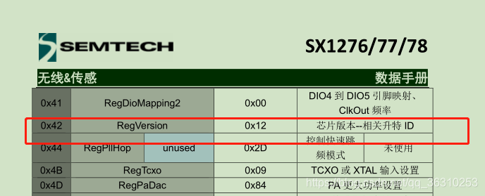
在第9节中的spi.c中定义了 get_vision_and_print() 函数,可以获取并打印版本号,可直接调用。如果打印出来的是 Lora init success 表示移植并接线成功。
10.1 main.c的实现
#include <stdio.h>

#include "platform.h"			// LoRa相关
#include "radio.h"				// LoRa相关
#include "sx1276-Hal.h"			// LoRa相关
#include "sx1276-LoRa.h"		// LoRa相关
#include "sx1276-LoRaMisc.h"	// LoRa相关

#include "stm8l15x.h"
#include "spi.h"
#include "uart.h"
#include "timer.h"

void main(void)
{
	uart_init();
	lora_dio_init();
	lora_spi_init();

	systic_init();

	get_vision_and_print();

	while(1)
	{

	}
}

// printf重定向到串口
int putchar (int c)
{
	/* Write a character to the USART */
	USART_SendData8(USART2, c);

	/* Loop until the end of transmission */
	while (USART_GetFlagStatus(USART2, USART_FLAG_TC) == RESET);

	return (c);
}
11. 总结
#emsp; LoRa移植过程步骤如下,最后直到整个工程编译没有错误并获取到版本号表示移植成功:


 648
648


 被折叠的 条评论
为什么被折叠?
被折叠的 条评论
为什么被折叠?
 到【灌水乐园】发言


