


VLAN
实验拓扑

实验需求
按如图将pc加入vlan
实验步骤
Switch(config)#vlan 10,20,30 #创建多个vlan
e0/0口加vlan
Switch(config)#int e0/0
Switch(config-if)#switchport mode access       #定义二层端口
Switch(config-if)#switchport access vlan 10    #将本端口加入vlan10中
e0/1口加vlan
Switch(config-if)#int e0/1
Switch(config-if)#switchport mode access
Switch(config-if)#switchport access vlan 20
将多个口加到vlan种
Switch(config)#int range e0/2-3
Switch(config-if-range)#switchport mode access
Switch(config-if-range)#switchport access vlan 30
Switch(config-if-range)#do show vlan  #查看vlan信息

VLAN Name                             Status    Ports
---- -------------------------------- --------- -------------------------------
1    default                          active
10   VLAN0010                         active    Et0/0
20   VLAN0020                         active    Et0/1
30   VLAN0030                         active    Et0/2, Et0/3
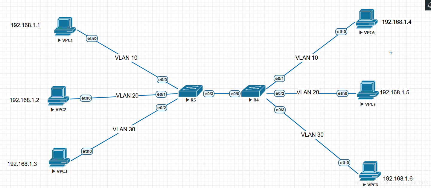
trunk
trunk:实现不同交换机的同一vlan通信
实验拓扑
VPCS> ip 192.168.1.1
2:交换机划vlan(省略)
3:两交换机相连之间配trunk
R4交换机配trunk
Switch(config-if)#int e0/0
Switch(config-if)#switchport trunk encapsulation dot1q  #选择封装协议为802.1q
Switch(config-if)#switchport mode trunk                         #将接口配置为trunk
R5交换机配trunk
Switch(config-if)#int e0/3
Switch(config-if)#switchport trunk encapsulation dot1q
Switch(config-if)#switchport mode trunk
测试
pc1 ping pc6
VPCS> ping 192.168.1.4

84 bytes from 192.168.1.4 icmp_seq=1 ttl=64 time=1.578 ms
84 bytes from 192.168.1.4 icmp_seq=2 ttl=64 time=2.181 ms
84 bytes from 192.168.1.4 icmp_seq=3 ttl=64 time=1.934 ms
84 bytes from 192.168.1.4 icmp_seq=4 ttl=64 time=0.701 ms
84 bytes from 192.168.1.4 icmp_seq=5 ttl=64 time=2.038 ms
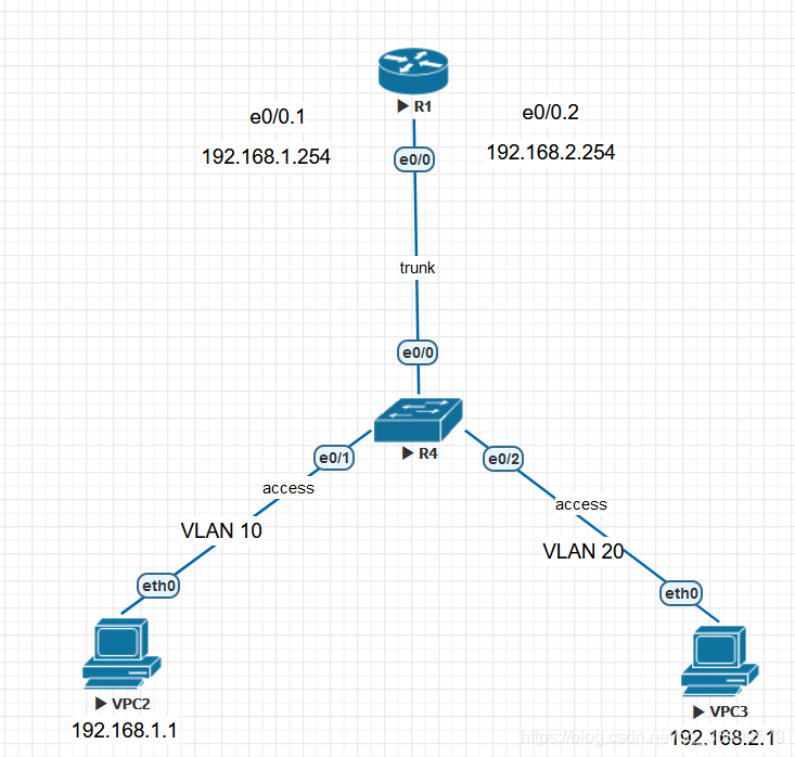
单臂路由
单臂路由:解决不同vlan之间的通信
实验拓扑
#vlan 10,20
Switch(config-vlan)#exit
2:把接口加到vlan中
Switch(config)#int e0/1
Switch(config-if)#switchport mode access
Switch(config-if)#switchport access vlan 10

Switch(config-if)#int e0/2
Switch(config-if)#switchport mode access
Switch(config-if)#switchport access vlan 20
3:配置trunk
Switch(config-if)#int e0/0
Switch(config-if)#switchport trunk encapsulation dot1q
Switch(config-if)#switchport mode trunk
Switch(config-if)#switchport trunk allowed vlan 10,20   #配置trunk口允许vlan 10和vlan20通过
路由器配置
1:将路由器开机
Router(config)#int e0/0
Router(config-if)#no shutdown
2:创建子接口,配置ip,并封装dot1q协议
 每个子接口必须封装dot1Q协议,并且标记相应的vlan id号,dot1Q协议主要是标记vlan的id号

Router(config-if)#int e0/0.1
Router(config-subif)#encapsulation dot1Q 10                #将vlan 10封装在子接口
Router(config-subif)#ip add 192.168.1.254 255.255.255.0    #子接口配置ip,作为vlan10的网关

Router(config-subif)#int e0/0.2
Router(config-subif)#encapsulation dot1Q 20
Router(config-subif)#ip add 192.168.2.254 255.255.255.0
PC配置
pc2配置
VPCS> ip 192.168.1.1 192.168.1.254
PC3配置
VPCS> ip 192.168.2.1 192.168.2.254
测试
pc3 ping pc2

VPCS> ping 192.168.1.1
84 bytes from 192.168.1.1 icmp_seq=1 ttl=63 time=5.581 ms
84 bytes from 192.168.1.1 icmp_seq=2 ttl=63 time=1.384 ms
84 bytes from 192.168.1.1 icmp_seq=3 ttl=63 time=2.158 ms
84 bytes from 192.168.1.1 icmp_seq=4 ttl=63 time=1.005 ms
84 bytes from 192.168.1.1 icmp_seq=5 ttl=63 time=1.968 ms
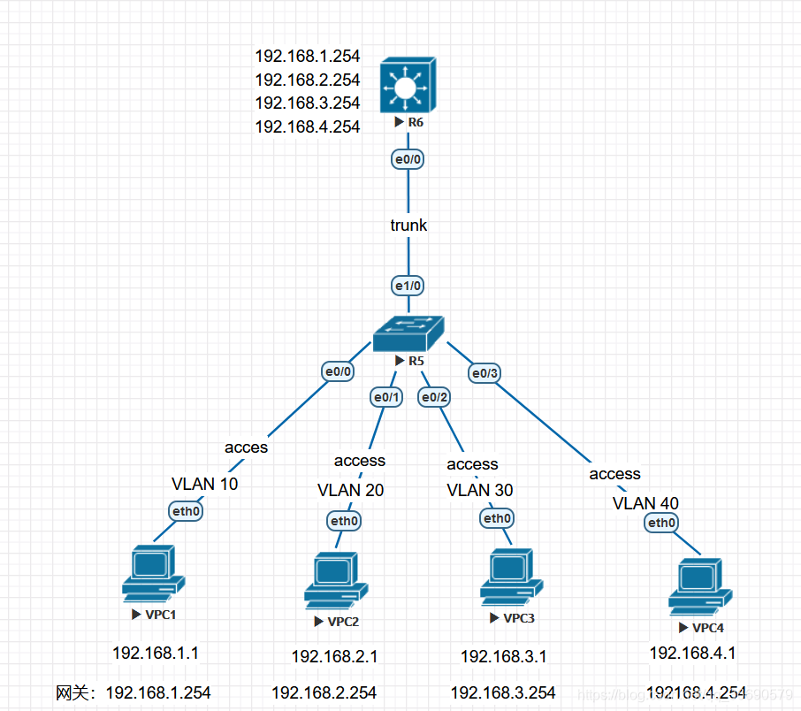
三层路由实现vlan间的通信
实验拓扑
2:二层交换机创建VLAN,将pc加入相应的VLAN中。(省略)
3:二层交换机在e1/0配置trunk(省略)
4:三层交换机创建VLAN(省略)
5:三层交换机在e1/0配置trunk
6:三层交换机配置虚接口
Switch(config)#interface vlan 10
Switch(config-if)#ip address 192.168.1.254 255.255.255.0
Switch(config-if)#no shutdown
Switch(config-if)#exit

Switch(config)#interface vlan 20
Switch(config-if)#ip address 192.168.2.254 255.255.255.0
Switch(config-if)#no shutdown
Switch(config-if)#exit

Switch(config)#interface vlan 30
Switch(config-if)#ip address 192.168.3.254 255.255.255.0
Switch(config-if)#no shutdown
Switch(config-if)#exit

Switch(config)#interface vlan 40
Switch(config-if)#ip address 192.168.4.254 255.255.255.0
Switch(config-if)#no shutdown
Switch(config-if)#exit
测试
PC1 ping pc4
PC>ping 192.168.4.1

Reply from 192.168.4.1: bytes=32 time=117ms TTL=128
Reply from 192.168.4.1: bytes=32 time=0ms TTL=128
Reply from 192.168.4.1: bytes=32 time=2ms TTL=128
Reply from 192.168.4.1: bytes=32 time=4ms TTL=128

Ping statistics for 192.168.4.1:
    Packets: Sent = 4, Received = 4, Lost = 0 (0% loss),
Approximate round trip times in milli-seconds:
    Minimum = 0ms, Maximum = 117ms, Average = 30ms
STP
mstp作用:从逻辑上断开链路,解决交换机之间的环路问题
实验拓扑

实验需求
配置mstp,
| 根端口 | 备份端口 | |
|---|---|---|
| sw1 | vlan 10 ,vlan 20 | vlan 30 |
| sw2 | vlan 30 | vlan 10,vlan20 |
实验步骤
1:交换机划vlan,交换机之间配置trunk
2:交换机与主机之间配置access
3:在r2配置三层交换
4:pc配置ip并将网关指向r2
5:配置rstp
RSTP
sw1(config)#spanning-tree vlan 10,20,30
sw1(config)#spanning-tree vlan 10,20 root primary #将10,20设置为根网桥
sw1(config)#spanning-tree vlan 30 root secondary #将30设置为默认网桥
sw2(config)#spanning-tree vlan 10,20,30
sw2(config)#spanning-tree vlan 30 root primary		 #将vlan30设置为根网桥
sw2(config)#spanning-tree vlan 10,20 root secondary  #将vlan10,20设置为默认网桥
测试
sw3(config)#do sh sp

VLAN0001
  Spanning tree enabled protocol rstp
  Root ID    Priority    32769
             Address     aabb.cc00.1000
             Cost        100
             Port        2 (Ethernet0/1)
             Hello Time   2 sec  Max Age 20 sec  Forward Delay 15 sec

  Bridge ID  Priority    32769  (priority 32768 sys-id-ext 1)
             Address     aabb.cc00.3000
             Hello Time   2 sec  Max Age 20 sec  Forward Delay 15 sec
             Aging Time  300 sec

Interface           Role Sts Cost      Prio.Nbr Type
------------------- ---- --- --------- -------- --------------------------------
Et0/0               Altn BLK 100       128.1    Shr
Et0/1               Root FWD 100       128.2    Shr
Et1/1               Desg FWD 100       128.6    Shr
Et1/2               Desg FWD 100       128.7    Shr
Et1/3               Desg FWD 100       128.8    Shr
Et2/0               Desg FWD 100       128.9    Shr
Et2/1               Desg FWD 100       128.10   Shr

Interface           Role Sts Cost      Prio.Nbr Type
------------------- ---- --- --------- -------- --------------------------------

Et2/2               Desg FWD 100       128.11   Shr
Et2/3               Desg FWD 100       128.12   Shr
Et3/0               Desg FWD 100       128.13   Shr
Et3/1               Desg FWD 100       128.14   Shr
Et3/2               Desg FWD 100       128.15   Shr
Et3/3               Desg FWD 100       128.16   Shr
Et4/0               Desg FWD 100       128.17   Shr
Et4/1               Desg FWD 100       128.18   Shr
Et4/2               Desg FWD 100       128.19   Shr
Et4/3               Desg FWD 100       128.20   Shr
Et5/0               Desg FWD 100       128.21   Shr
Et5/1               Desg FWD 100       128.22   Shr
Et5/2               Desg FWD 100       128.23   Shr
Et5/3               Desg FWD 100       128.24   Shr
Et6/0               Desg FWD 100       128.25   Shr
Et6/1               Desg FWD 100       128.26   Shr
Et6/2               Desg FWD 100       128.27   Shr
Et6/3               Desg FWD 100       128.28   Shr
Et7/0               Desg FWD 100       128.29   Shr
Et7/1               Desg FWD 100       128.30   Shr
Et7/2               Desg FWD 100       128.31   Shr
Et7/3               Desg FWD 100       128.32   Shr


VLAN0010
  Spanning tree enabled protocol rstp
  Root ID    Priority    24586
             Address     aabb.cc00.1000
             Cost        100
             Port        2 (Ethernet0/1)
             Hello Time   2 sec  Max Age 20 sec  Forward Delay 15 sec

  Bridge ID  Priority    32778  (priority 32768 sys-id-ext 10)
             Address     aabb.cc00.3000
             Hello Time   2 sec  Max Age 20 sec  Forward Delay 15 sec
             Aging Time  300 sec

Interface           Role Sts Cost      Prio.Nbr Type
------------------- ---- --- --------- -------- --------------------------------
Et0/0               Altn BLK 100       128.1    Shr
Et0/1               Root FWD 100       128.2    Shr
Et1/0               Desg FWD 100       128.5    Shr


VLAN0020
  Spanning tree enabled protocol rstp
  Root ID    Priority    20500
             Address     aabb.cc00.1000
             Cost        100
             Port        2 (Ethernet0/1)
             Hello Time   2 sec  Max Age 20 sec  Forward Delay 15 sec

  Bridge ID  Priority    32788  (priority 32768 sys-id-ext 20)
             Address     aabb.cc00.3000
             Hello Time   2 sec  Max Age 20 sec  Forward Delay 15 sec
             Aging Time  300 sec

Interface           Role Sts Cost      Prio.Nbr Type
------------------- ---- --- --------- -------- --------------------------------
Et0/0               Altn BLK 100       128.1    Shr
Et0/1               Root FWD 100       128.2    Shr
Et0/3               Desg FWD 100       128.4    Shr


VLAN0030
  Spanning tree enabled protocol rstp
  Root ID    Priority    20510
             Address     aabb.cc00.2000
             Cost        100
             Port        1 (Ethernet0/0)
             Hello Time   2 sec  Max Age 20 sec  Forward Delay 15 sec

  Bridge ID  Priority    32798  (priority 32768 sys-id-ext 30)
             Address     aabb.cc00.3000
             Hello Time   2 sec  Max Age 20 sec  Forward Delay 15 sec
             Aging Time  300 sec

Interface           Role Sts Cost      Prio.Nbr Type
------------------- ---- --- --------- -------- --------------------------------
Et0/0               Root FWD 100       128.1    Shr
Et0/1               Altn BLK 100       128.2    Shr
Et0/2               Desg FWD 100       128.3    Shr
| root | 根 |
|---|---|
| altn | 阻塞 |
| desg | 备份 |
配置mstp(重复前四个步骤)
MSTP
sw1(config)#spanning-tree mode mst
sw1(config)#spanning-tree mst configuration
sw1(config-mst)#revision 2
sw1(config-mst)#instance 1 vlan 10,20                  #把vlan10,20加入实例1
sw1(config-mst)#instance 2 vlan 30                     #把vlan30加入实例2
sw1(config-mst)#exit
sw1(config)#spanning-tree mst 1 root primary           #把实例1加入根网桥
sw1(config)#spanning-tree mst 2 root secondary         #把实例2加入备份网桥
sw2(config)#spanning-tree mode mst
sw2(config)#spanning-tree mst configuration
sw2(config-mst)#revision 2
sw2(config-mst)#instance 1 vlan 30                   #把vlan30加入实例1
sw2(config-mst)#instance 2 vlan 10,20                #把vklan 10,20加入实例2
sw2(config-mst)#exit
sw2(config)#spanning-tree mst 1 root primary         #把实例1加入根网桥
sw2(config)#spanning-tree mst 2 root secondary       #把实例2加入备份网桥
静态路由
RIP实验
实验拓扑:

实验需求
实现全网通
实验思路:
第一步:配置ip(省略)
第二步:宣告网段
实验步骤:
R1配置rip
Router(config)#ruoter rip
RouRouter(config-router)#version 2
Router(config-router)#no auto-summary    (关闭自动汇总)
Router(config-router)#network 12.12.12.0 (宣告与路由器直连的网段)
R2配置rip
Router(config)#router rip
Router(config-router)#version 2
Router(config-router)#no auto-summary
Router(config-router)#network 12.12.12.0
Router(config-router)#network 23.23.23.0
Router(config-router)#network 24.24.24.0
R3配置ip
Router(config)#router rip
Router(config-router)#version 2
Router(config-router)#no auto-summary
Router(config-router)#network 23.23.23.0
Router(config-router)#network 34.34.34.0
R4配置rip
Router(config)#router rip
Router(config-router)#version 2
Router(config-router)#no auto-summary
RRouter(config-router)#network 24.24.24.0
Router(config-router)#network 34.34.34.0
实验测试
R4 ping R1
Router(config-router)#do ping 12.12.12.1
Type escape sequence to abort.
Sending 5, 100-byte ICMP Echos to 12.12.12.1, timeout is 2 seconds:
!!!!!
Success rate is 100 percent (5/5), round-trip min/avg/max = 5/5/6 ms
实验成功
ospf实验
实验拓扑
 实验需求
实验需求
实现全网通
实验步骤
1:配置ip(省略)
2: 配置本地环回测试接口,并作为router id使用
R1(config)#int lo0
R1(config-if)#ip add 1.1.1.1 255.255.255.0
R2(config)#int lo0
R2(config-if)#ip add 2.2.2.2 255.255.255.0
R3(config)#int lo0
R3(config-if)#ip add 3.3.3.3 255.255.255.0
R4(config)#int lo0
R4(config-if)#ip add 4.4.4.4 255.255.255.0
3:配置ospf
R1(config)#router ospf 1
R1(config-router)#router-id 1.1.1.1
R1(config-router)#net 192.168.1.0 0.0.0.255 area 1 #宣告直连网段
R2(config)#router ospf 1
R2(config-router)#router-id 2.2.2.2
R2(config-router)#net 192.168.1.0 0.0.0.255 area 1
R2(config-router)#net 192.168.2.0 0.0.0.255 area 0
R3(config)#router ospf 1
R3(config-router)#router-id 3.3.3.3
R3(config-router)#net 192.168.2.0 0.0.0.255 area 0
R3(config-router)#net 192.168.3.0 0.0.0.255 area 2
R4(config)#router ospf 1
R4(config-router)#router-id 4.4.4.4
R4(config-router)#net 192.168.3.2 0.0.0.255 area 2
4:测试
R4#ping 192.168.1.1
Type escape sequence to abort.
Sending 5, 100-byte ICMP Echos to 192.168.1.1, timeout is 2 seconds:
!!!!!
Success rate is 100 percent (5/5), round-trip min/avg/max = 1/1/1 ms
实验结论
rip与ospf接入
实验拓扑

实验需求
如图配置rip与ospf并实现全网通
实验步骤
第一步:配置ip(省略)
第二步:配置rip和ospf(注意R1 e0/0口配ospf,e0/1口配置rip)(其他省略)
R1配置rip
R1(config)#router rip
R1(config-router)#version 2
R1(config-router)#net 192.168.4.0
R1(config-router)#no auto-summary
R1(config-router)#exit


R1配置ospf
R1(config)#router ospf 1
R1(config-router)#router-id 1.1.1.1
R1(config-router)#net 192.168.1.0 0.0.0.255 area 1
R1(config-router)#exit
第三步:引入路由
R1引入路由
R7(config)#router rip
R7(config-router)#redistribute ospf 1 metric 10
R7(config-router)#exit
R1引入路由
R7config)#router ospf 1
R7(config-router)#$ig-router)#redistribute rip metric 200 subnets
R7(config-router)#redistribute rip metric 200 subnets
第四步:测试网络连通性(用 R7 ping R4 )
R7(config)#do ping 192.168.3.2
Type escape sequence to abort.
Sending 5, 100-byte ICMP Echos to 192.168.3.2, timeout is 2 seconds:
!!!!!
Success rate is 100 percent (5/5), round-trip min/avg/max = 3/3/3 ms


 643
643

 被折叠的 条评论
为什么被折叠?
被折叠的 条评论
为什么被折叠?
 到【灌水乐园】发言


