


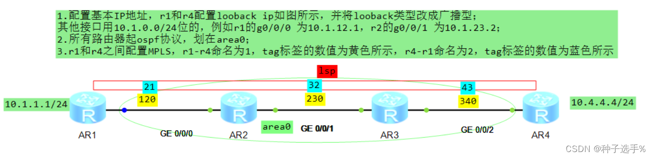
全部配置及注释
AR1配置
#
sysname r1
#
mpls lsr-id 1.1.1.1
mpls//在全局使能MPLS
#
//去往目的网络10.4.4.0 下一跳 10.1.12.2 出去时打上 120的tag标签
static-lsp ingress 1 destination 10.4.4.0 24 nexthop 10.1.12.2 out-label 120
//去往目的网络10.4.4.0 下一跳 10.1.12.2 出去时打上 120的tag标签
static-lsp egress 2 incoming-interface GigabitEthernet0/0/0 in-label 21
//边沿路由器LER,从g0/0/0接口进来的标签是21
#
interface GigabitEthernet0/0/0
ip address 10.1.12.1 255.255.255.0 //ip地址配置
ospf enable 1 area 0.0.0.0 //ospf端口线下使能,与network作用一致
mpls //在端口下使能MPLS
#
interface LoopBack0 //创建并进入looback 0接口
ip address 10.1.1.1 255.255.255.0
ospf network-type broadcast //将ospf连接类型改成广播型
#
ospf 1 router-id 1.1.1.1 //创建ospf进程1 id号为1.1.1.1
area 0.0.0.0 //创建并进入区域0
network 10.1.1.0 0.0.0.0.255//通告10.1.1.0网络
#
AR2配置
#
sysname r2
#
mpls lsr-id 2.2.2.2
mpls
#
interface GigabitEthernet0/0/0
ip address 10.1.12.2 255.255.255.0
ospf enable 1 area 0.0.0.0
mpls
#
interface GigabitEthernet0/0/1
ip address 10.1.23.2 255.255.255.0
ospf enable 1 area 0.0.0.0
mpls
#
ospf 1 router-id 2.2.2.2
area 0.0.0.0
#
static-lsp transit 1 incoming-interface GigabitEthernet0/0/0 in-label 120 nextho
p 10.1.23.3 out-label 230 //核心LSR,从g0/0/0进来的标签是120 出去的
时候拆掉旧的打上新的230,下一跳是10.1.23.3
static-lsp transit 2 incoming-interface GigabitEthernet0/0/1 in-label 32 nexthop
10.1.12.1 out-label 21
#
AR3配置
#
sysname r3
#
mpls lsr-id 3.3.3.3
mpls
#
interface GigabitEthernet0/0/1
ip address 10.1.23.3 255.255.255.0
ospf enable 1 area 0.0.0.0
mpls
#
interface GigabitEthernet0/0/2
ip address 10.1.34.3 255.255.255.0
ospf enable 1 area 0.0.0.0
mpls
#
static-lsp transit 1 incoming-interface GigabitEthernet0/0/1 in-label 230 nextho
p 10.1.34.4 out-label 340 //核心LSR,从g0/0/0进来的标签是230 出去的
时候拆掉旧的打上新的340,下一跳是10.1.34.4
static-lsp transit 2 incoming-interface GigabitEthernet0/0/2 in-label 43 nexthop
10.1.23.2 out-label 32
#
AR4配置
#
sysname r4
#
mpls lsr-id 4.4.4.4
mpls
#
interface GigabitEthernet0/0/2
ip address 10.1.34.4 255.255.255.0
ospf enable 1 area 0.0.0.0
mpls
#
interface LoopBack0
ip address 10.4.4.4 255.255.255.0
ospf network-type broadcast
#
ospf 1 router-id 4.4.4.4
area 0.0.0.0
network 10.4.4.4 0.0.0.0
#
static-lsp egress 1 incoming-interface GigabitEthernet0/0/2 in-label 340
//边沿路由器LER,从g0/0/0接口进来的标签是340
static-lsp ingress 2 destination 10.1.1.0 24 nexthop 10.1.34.3 out-label 43
#
下图为r4通过MPLS 标签ping r1上的10.1.1.0网络,显示如图则为lsp 1 建立成功

下图为在r1 ping 10.4.4.0网络后,在g0/0/0口抓的包,显示为优先选择标签转发(mpls)

详细请查看资源包


 729
729


 被折叠的 条评论
为什么被折叠?
被折叠的 条评论
为什么被折叠?
 到【灌水乐园】发言


