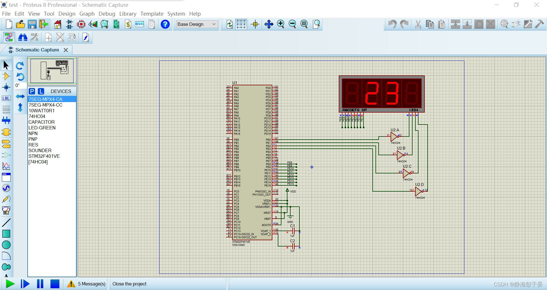
八位数码管 基于stm32

 引脚初始化

void SEG_Init(void)
{    	 
	GPIO_InitTypeDef  GPIO_InitStructure;

	RCC_AHB1PeriphClockCmd(RCC_AHB1Periph_GPIOE, ENABLE);//ʹÄÜGPIOEʱÖÓ
	
	GPIO_InitStructure.GPIO_Pin=GPIO_Pin_0 | GPIO_Pin_1 | GPIO_Pin_2 | GPIO_Pin_3 | GPIO_Pin_8 | GPIO_Pin_9 | GPIO_Pin_10 | GPIO_Pin_11 |  GPIO_Pin_12 | GPIO_Pin_13 | GPIO_Pin_14 | GPIO_Pin_15;
	GPIO_InitStructure.GPIO_Mode=GPIO_Mode_OUT;//ÆÕͨÊä³öģʽ
	GPIO_InitStructure.GPIO_PuPd=GPIO_PuPd_UP;//ÉÏÀ­
	GPIO_InitStructure.GPIO_OType=GPIO_OType_PP;//ÍÆÍìÊä³ö
	GPIO_InitStructure.GPIO_Speed=GPIO_Speed_100MHz;//100MHz
	GPIO_Init(GPIOE,&GPIO_InitStructure);//³õʼ»¯
	GPIO_SetBits(GPIOE,GPIO_Pin_0 | GPIO_Pin_1 |
  • 0
    点赞
  • 0
    收藏
    觉得还不错? 一键收藏
  • 打赏
    打赏
  • 0
    评论
stm32八位串行595数码管 #include "sys.h" //点击魔术棒加入对应的文件夹地址,FWLIB里加入相应的头文件 #include "delay.h" #include "usart.h" #include "led.h" #include "key.h" //////////////////////////////////////////////////////////////////////////// unsigned char fseg[]={0xc0,0xf9,0xa4,0xb0,0x99,0x92,0x82,0xf8,0x80,0x90}; unsigned char segbit[]={0x80,0x40,0x20,0x10,0x08,0x04,0x02,0x01}; unsigned char disbuf[8]={0,0,0,0,0,0,0,0}; #define uchar unsigned char #define DIO LED0//串行数据输入 #define RCLK LED1 //时钟脉冲信号——上升沿有效 #define SCLK LED2//打入信号————上升沿有效 void LED4_Display (void); // LED显示 void LED_OUT(uchar X); // LED单字节串行移位函数 void data_OUT(int data); unsigned char LED_0F[]; // LED字模表 //----------------------------------------------------------------------------- // 全局变量 uchar LED[8]; //用于LED的8位显示缓存 /////////////////////////////////////////////////////////////////////////////////// int main(void) { u8 t=0; delay_init(); //延时函数初始化 NVIC_Configuration(); //设置NVIC中断分组2:2位抢占优先级,2位响应优先级 uart_init(9600); //串口初始化为9600 LED_Init(); KEY_Init(); ////////////////////////////////////////////////////////// // LED[0]=0; // LED[1]=2; // LED[2]=3; // LED[3]=4; // LED[4]=5; // LED[5]=6; // LED[6]=7; // LED[7]=8; ///////////////////////////////////////////////////////////////// while(1) { LED4_Display ();//串口数码管 data_OUT(123456); // printf("love"); } } ///////////////////////////////////////////////////////////////// void LED4_Display (void) { unsigned char *led_table; // 查表指针 uchar i; //显示第1位 led_table = LED_0F + LED[0]; i = *led_table; LED_OUT(i); LED_OUT(0x01); RCLK = 0; RCLK = 1; //显示第2位 led_table = LED_0F + LED[1]; i = *led_table; LED_OUT(i); LED_OUT(0x02); RCLK = 0; RCLK = 1; //显示第3位 led_table = LED_0F + LED[2]; i = *led_table; LED_OUT(i); LED_OUT(0x04); RCLK = 0; RCLK = 1; //显示第4位 led_table = LED_0F + LED[3]; i = *led_table; LED_OUT(i); LED_OUT(0x08); RCLK = 0; RCLK = 1; //显示第5位 led_table = LED_0F + LED[4]; i = *led_table; LED_OUT(i); LED_OUT(0x10); RCLK = 0; RCLK = 1; //显示第6位 led_table = LED_0F + LED[5]; i = *led_table; LED_OUT(i); LED_OUT(0x20); RCLK = 0; RCLK = 1; //显示第7位 led_table = LED_0F + LED[6]; i = *led_table; LED_OUT(i); LED_OUT(0x40); RCLK = 0; RCLK = 1; //显示第8位 led_table = LED_0F + LED[7]; i = *led_table; LED_OUT(i); LED_OUT(0x80); RCLK = 0; RCLK = 1; } void LED_OUT(uchar X) { uchar i; for(i=8;i>=1;i--) { if (X&0x80) DIO=1; else DIO=0; X<<=1; SCLK = 0; SCLK = 1; } } void data_OUT(int data) { LED[7] = 0; LED[6] = 0; LED[5] = data % 1000000 / 100000; LED[4] = data % 100000 / 10000; // LED[3] = data % 10000 / 1000; LED[2] = data % 1000 / 100; LED[1] = data % 100 / 10; LED[0] = data % 10; } unsigned char LED_0F[] = {// 0 1 2 3 4 5 6 7 8 9 A b C d E F - 0xC0,0xF9,0xA4,0xB0,0x99,0x92,0x82,0xF8,0x80,0x90,0x8C,0xBF,0xC6,0xA1,0x86,0xFF,0xbf }; ///////////////////////////////////////////////////////////////////////////////////////////////
要控制八位数码管,你需要了解以下几个方面: 1. 数码管的工作原理:数码管是由多个LED组成,每个LED代表不同的数字或字符。通过对不同的LED进行亮灭控制,可以显示不同的数字或字符。 2. 数码管的接口:通常,数码管的接口包括8个控制引脚和1个共阴或共阳引脚。其中,8个控制引脚分别对应8个LED,用于控制它们的亮灭;共阴或共阳引脚则用于控制所有LED的共性端。 3. 控制方法:控制数码管的方法有很多种,常见的方式包括直接控制、定时器控制和中断控制等。在这里,我们以直接控制为例。 下面是一个简单的用STM32C8T6控制8位数码管的代码示例,假设使用的是共阴数码管: ```c #include "stm32f10x.h" #define GPIO_LED_PORT GPIOA #define GPIO_LED_PIN_0 GPIO_Pin_0 #define GPIO_LED_PIN_1 GPIO_Pin_1 #define GPIO_LED_PIN_2 GPIO_Pin_2 #define GPIO_LED_PIN_3 GPIO_Pin_3 #define GPIO_LED_PIN_4 GPIO_Pin_4 #define GPIO_LED_PIN_5 GPIO_Pin_5 #define GPIO_LED_PIN_6 GPIO_Pin_6 #define GPIO_LED_PIN_7 GPIO_Pin_7 void delay(uint32_t count) { for(uint32_t i=0;i<count;i++); } int main(void) { GPIO_InitTypeDef GPIO_InitStructure; RCC_APB2PeriphClockCmd(RCC_APB2Periph_GPIOA, ENABLE); GPIO_InitStructure.GPIO_Pin = GPIO_LED_PIN_0 | GPIO_LED_PIN_1 | GPIO_LED_PIN_2 | GPIO_LED_PIN_3 | GPIO_LED_PIN_4 | GPIO_LED_PIN_5 | GPIO_LED_PIN_6 | GPIO_LED_PIN_7; GPIO_InitStructure.GPIO_Mode = GPIO_Mode_Out_PP; GPIO_InitStructure.GPIO_Speed = GPIO_Speed_50MHz; GPIO_Init(GPIO_LED_PORT, &GPIO_InitStructure); while(1) { GPIO_SetBits(GPIO_LED_PORT, GPIO_LED_PIN_0 | GPIO_LED_PIN_1 | GPIO_LED_PIN_2 | GPIO_LED_PIN_3 | GPIO_LED_PIN_4 | GPIO_LED_PIN_5 | GPIO_LED_PIN_6 | GPIO_LED_PIN_7); // 显示数字0 GPIO_ResetBits(GPIO_LED_PORT, GPIO_LED_PIN_0 | GPIO_LED_PIN_1 | GPIO_LED_PIN_2 | GPIO_LED_PIN_3 | GPIO_LED_PIN_4 | GPIO_LED_PIN_5); delay(1000); // 显示数字1 GPIO_ResetBits(GPIO_LED_PORT, GPIO_LED_PIN_1 | GPIO_LED_PIN_2); delay(1000); // 显示数字2 GPIO_ResetBits(GPIO_LED_PORT, GPIO_LED_PIN_0 | GPIO_LED_PIN_1 | GPIO_LED_PIN_3 | GPIO_LED_PIN_4 | GPIO_LED_PIN_6); delay(1000); // 显示数字3 GPIO_ResetBits(GPIO_LED_PORT, GPIO_LED_PIN_0 | GPIO_LED_PIN_1 | GPIO_LED_PIN_2 | GPIO_LED_PIN_3 | GPIO_LED_PIN_6); delay(1000); // 显示数字4 GPIO_ResetBits(GPIO_LED_PORT, GPIO_LED_PIN_1 | GPIO_LED_PIN_2 | GPIO_LED_PIN_5 | GPIO_LED_PIN_6); delay(1000); // 显示数字5 GPIO_ResetBits(GPIO_LED_PORT, GPIO_LED_PIN_0 | GPIO_LED_PIN_2 | GPIO_LED_PIN_3 | GPIO_LED_PIN_5 | GPIO_LED_PIN_6); delay(1000); // 显示数字6 GPIO_ResetBits(GPIO_LED_PORT, GPIO_LED_PIN_0 | GPIO_LED_PIN_2 | GPIO_LED_PIN_3 | GPIO_LED_PIN_4 | GPIO_LED_PIN_5 | GPIO_LED_PIN_6); delay(1000); // 显示数字7 GPIO_ResetBits(GPIO_LED_PORT, GPIO_LED_PIN_0 | GPIO_LED_PIN_1 | GPIO_LED_PIN_2); delay(1000); // 显示数字8 GPIO_ResetBits(GPIO_LED_PORT, GPIO_LED_PIN_0 | GPIO_LED_PIN_1 | GPIO_LED_PIN_2 | GPIO_LED_PIN_3 | GPIO_LED_PIN_4 | GPIO_LED_PIN_5 | GPIO_LED_PIN_6); delay(1000); // 显示数字9 GPIO_ResetBits(GPIO_LED_PORT, GPIO_LED_PIN_0 | GPIO_LED_PIN_1 | GPIO_LED_PIN_2 | GPIO_LED_PIN_3 | GPIO_LED_PIN_5 | GPIO_LED_PIN_6); delay(1000); } } ``` 这个示例代码中,GPIO_LED_PORT对应的是数码管的8个控制引脚,GPIO_LED_PIN_0至GPIO_LED_PIN_7分别对应8个LED。在while循环中,通过依次控制每个LED的亮灭,来实现8位数码管的显示。

“相关推荐”对你有帮助么?

  • 非常没帮助
  • 没帮助
  • 一般
  • 有帮助
  • 非常有帮助
提交
评论
添加红包

请填写红包祝福语或标题

红包个数最小为10个

红包金额最低5元

当前余额3.43前往充值 >
需支付:10.00
成就一亿技术人!
领取后你会自动成为博主和红包主的粉丝 规则
hope_wisdom
发出的红包

打赏作者

静海彭于晏

你的鼓励将是我创作的最大动力

¥1 ¥2 ¥4 ¥6 ¥10 ¥20
扫码支付:¥1
获取中
扫码支付

您的余额不足,请更换扫码支付或充值

打赏作者

实付
使用余额支付
点击重新获取
扫码支付
钱包余额 0

抵扣说明:

1.余额是钱包充值的虚拟货币,按照1:1的比例进行支付金额的抵扣。
2.余额无法直接购买下载,可以购买VIP、付费专栏及课程。

余额充值