


实验 - 配置基本的单区域 OSPFv2
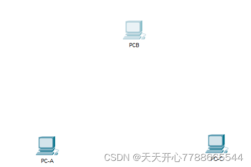
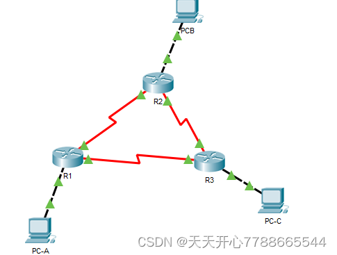
拓扑
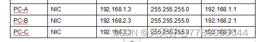
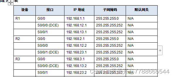
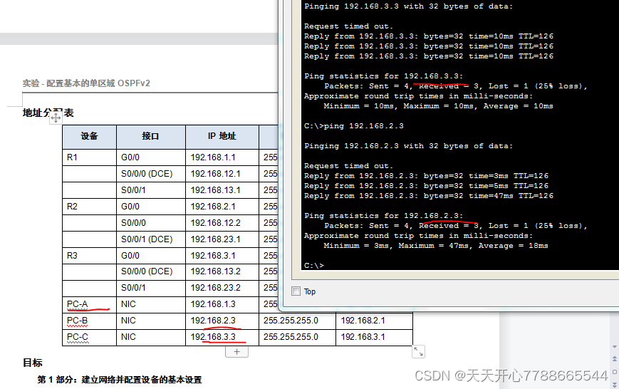
地址分配表
设备 接口 IP 地址 子网掩码 默认网关
R1 G0/0 192.168.1.1 255.255.255.0 N/A
S0/0/0 (DCE) 192.168.12.1 255.255.255.252 N/A
S0/0/1 192.168.13.1 255.255.255.252 N/A
R2 G0/0 192.168.2.1 255.255.255.0 N/A
S0/0/0 192.168.12.2 255.255.255.252 N/A
S0/0/1 (DCE) 192.168.23.1 255.255.255.252 N/A
R3 G0/0 192.168.3.1 255.255.255.0 N/A
S0/0/0 (DCE) 192.168.13.2 255.255.255.252 N/A
S0/0/1 192.168.23.2 255.255.255.252 N/A
PC-A NIC 192.168.1.3 255.255.255.0 192.168.1.1
PC-B NIC 192.168.2.3 255.255.255.0 192.168.2.1
PC-C NIC 192.168.3.3 255.255.255.0 192.168.3.1
目标
第 1 部分:建立网络并配置设备的基本设置
第 2 部分:配置并检验 OSPF 路由
第 3 部分:更改路由器 ID 分配
第 4 部分:配置 OSPF 被动接口
第 5 部分:更改 OSPF 度量
背景/场景
开放最短路径优先 (OSPF) 是用于 IP 网络的链路状态路由协议。OSPFv2 适用于 IPv4 网络,而 OSPFv3 适用于 IPv6 网络。OSPF 能够检测拓扑变化(例如链路故障),并且能在新的无环路由结构上快速收敛。它使用 Dijkstra 算法(即最短路径优先算法)来计算每个路由。
在本实验中,您将使用 OSPFv2 路由配置网络拓扑、更改路由器 ID 分配、配置被动接口、调整 OSPF 度量,并使用大量的 CLI 命令显示和检验 OSPF 路由信息。
注意:CCNA 动手实验所用的路由器是采用 Cisco IOS Release 15.2(4)M3(universalk9 映像)的 Cisco 1941 集成多业务路由器 (ISR)。也可使用其他路由器以及 Cisco IOS 版本。根据型号以及 Cisco IOS 版本不同,可用命令和产生的输出可能与实验显示的不一样。请参考本实验末尾的“路由器接口摘要表”以了解正确的接口标识符。
注意:请确保已经清除路由器的启动配置。如果不确定,请联系教师。
所需资源
3 台路由器(支持 Cisco IOS 15.2(4)M3 版通用映像的 Cisco 1941 或同类路由器)
3 台 PC(采用 Windows 7、Vista 或 XP 且支持终端模拟程序,比如 Tera Term)
用于通过控制台电缆配置 Cisco IOS 设备的控制台端口
如拓扑所示的以太网电缆和串行电缆
第 1 部分:建立网络并配置设备的基本设置
在第 1 部分,您需要建立网络拓扑并配置 PC 主机和路由器的基本设置。
第 1 步:建立如拓扑图所示的网络。
第 2 步:根据需要初始化并重新加载路由器。
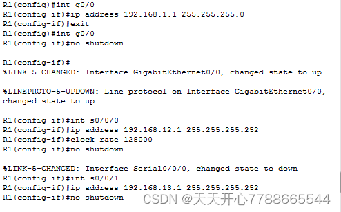
第 3 步:配置每个路由器的基本设置。
a.禁用 DNS 查找。
b.如拓扑所示配置设备名称。
c.指定 class 为特权 EXEC 密码。
d.指定 cisco 为控制台密码和 vty 密码。
e.配置一个向用户发出警告的当日消息 (MOTD) 标语:未经授权,禁止访问。
f.为控制台线路配置 logging synchronous。
g.在所有接口上配置地址分配表中列出的地址。
h.将所有 DCE 串行接口的时钟频率设置为 128000。
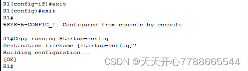
i.将运行配置复制到启动配置。
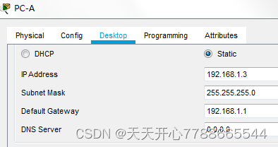
第 4 步:配置 PC 主机。
第 5 步:测试连通性。
路由器应该能够相互执行 ping 操作,并且每台 PC 都应该能对其默认网关执行 ping 操作。如果不配置 OSPF 路由,PC 就无法对其他 PC 执行 ping 操作。如果需要,请检验并排除故障。
第 2 部分:配置并检验 OSPF 路由
在第 2 部分,您将为网络中的所有路由器配置 OSPFv2 路由,然后检验路由表是否正确更新。检验 OSPF 之后,您需要在链路上配置 OSPF 身份验证以增强安全性。
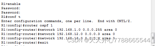
第 1 步:在 R1 上配置 OSPF。
a.在 R1 上,在全局配置模式下使用 router ospf 命令启用 OSPF。
R1(config)# router ospf 1
注意:OSPF 进程 ID 具有本地意义,对网络中的其他路由器没有任何意义。
b.为 R1 上的网络配置 network 语句。使用区域 ID 0。
R1(config-router)# network 192.168.1.0 0.0.0.255 area 0
R1(config-router)# network 192.168.12.0 0.0.0.3 area 0
R1(config-router)# network 192.168.13.0 0.0.0.3 area 0
第 2 步:在 R2 和 R3 上配置 OSPF。
在 R2 和 R3 上使用 router ospf 命令并添加 network 语句。当 R2 和 R3 上配置了 OSPF 路由时,R1 上会显示邻居邻接消息。
R1#
00:22:29: %OSPF-5-ADJCHG: Process 1, Nbr 192.168.23.1 on Serial0/0/0 from LOADING to FULL, Loading Done
R1#
00:23:14: %OSPF-5-ADJCHG: Process 1, Nbr 192.168.23.2 on Serial0/0/1 from LOADING to FULL, Loading Done
R1#
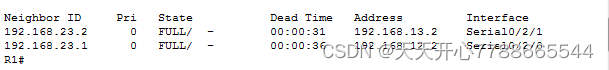
第 3 步:检验 OSPF 邻居和路由信息。
a.发出 show ip ospf neighbor 命令,以检验每台路由器是否将网络中的其他路由器列为邻居。
R1# show ip ospf neighbor
Neighbor ID Pri State Dead Time Address Interface
192.168.23.2 0 FULL/ - 00:00:33 192.168.13.2 Serial0/0/1
192.168.23.1 0 FULL/ - 00:00:30 192.168.12.2 Serial0/0/0
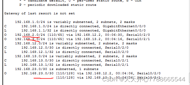
b.发出 show ip route 命令,以检验所有路由器的路由表中是否显示所有网络。
R1# show ip route
Codes: L - local, C - connected, S - static, R - RIP, M - mobile, B - BGP
D - EIGRP, EX - EIGRP external, O - OSPF, IA - OSPF inter area
N1 - OSPF NSSA external type 1, N2 - OSPF NSSA external type 2
E1 - OSPF external type 1, E2 - OSPF external type 2, E - EGP
i - IS-IS, L1 - IS-IS level-1, L2 - IS-IS level-2, ia - IS-IS inter area
* - candidate default, U - per-user static route, o - ODR
P - periodic downloaded static route
Gateway of last resort is not set
192.168.1.0/24 is variably subnetted, 2 subnets, 2 masks
C 192.168.1.0/24 is directly connected, GigabitEthernet0/0
L 192.168.1.1/32 is directly connected, GigabitEthernet0/0
O 192.168.2.0/24 [110/65] via 192.168.12.2, 00:32:33, Serial0/0/0
O 192.168.3.0/24 [110/65] via 192.168.13.2, 00:31:48, Serial0/0/1
192.168.12.0/24 is variably subnetted, 2 subnets, 2 masks
C 192.168.12.0/30 is directly connected, Serial0/0/0
L 192.168.12.1/32 is directly connected, Serial0/0/0
192.168.13.0/24 is variably subnetted, 2 subnets, 2 masks
C 192.168.13.0/30 is directly connected, Serial0/0/1
L 192.168.13.1/32 is directly connected, Serial0/0/1
192.168.23.0/30 is subnetted, 1 subnets
O 192.168.23.0/30 [110/128] via 192.168.12.2, 00:31:38, Serial0/0/0
[110/128] via 192.168.13.2, 00:31:38, Serial0/0/1
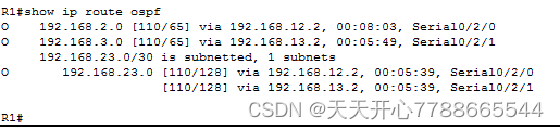
使用什么命令可以只查看路由表中的 OSPF 路由?
show ip route ospf
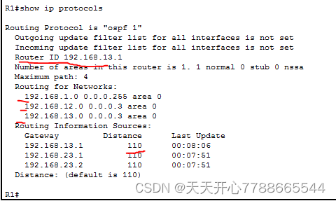
第 4 步:检验 OSPF 协议设置。
show ip protocols 命令可用于快速检验关键的 OSPF 配置信息。信息包括 OSPF 进程 ID、路由器 ID、路由器通告的网络、路由器接收更新的邻居、默认管理距离(OSPF 中为 110)。
R1# show ip protocols
*** IP Routing is NSF aware ***
Routing Protocol is “ospf 1”
Outgoing update filter list for all interfaces is not set
Incoming update filter list for all interfaces is not set
Router ID 192.168.13.1
Number of areas in this router is 1. 1 normal 0 stub 0 nssa
Maximum path: 4
Routing for Networks:
192.168.1.0 0.0.0.255 area 0
192.168.12.0 0.0.0.3 area 0
192.168.13.0 0.0.0.3 area 0
Routing Information Sources:
Gateway Distance Last Update
192.168.23.2 110 00:19:16
192.168.23.1 110 00:20:03
Distance: (default is 110)
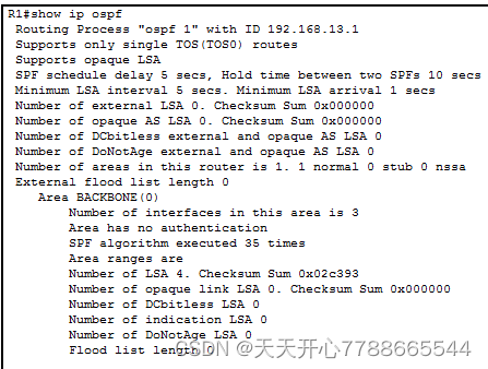
第 5 步:检验 OSPF 进程信息。
使用 show ip ospf 命令可以检查 OSPF 进程 ID 和路由器 ID。此命令显示 OSPF 区域信息以及上次计算 SPF 算法的时间。
R1# show ip ospf
Routing Process “ospf 1” with ID 192.168.13.1
Start time: 00:20:23.260, Time elapsed: 00:25:08.296
Supports only single TOS(TOS0) routes
Supports opaque LSA
Supports Link-local Signaling (LLS)
Supports area transit capability
Supports NSSA (compatible with RFC 3101)
Event-log enabled, Maximum number of events: 1000, Mode: cyclic
Router is not originating router-LSAs with maximum metric
Initial SPF schedule delay 5000 msecs
Minimum hold time between two consecutive SPFs 10000 msecs
Maximum wait time between two consecutive SPFs 10000 msecs
Incremental-SPF disabled
Minimum LSA interval 5 secs
Minimum LSA arrival 1000 msecs
LSA group pacing timer 240 secs
Interface flood pacing timer 33 msecs
Retransmission pacing timer 66 msecs
Number of external LSA 0. Checksum Sum 0x000000
Number of opaque AS LSA 0. Checksum Sum 0x000000
Number of DCbitless external and opaque AS LSA 0
Number of DoNotAge external and opaque AS LSA 0
Number of areas in this router is 1. 1 normal 0 stub 0 nssa
Number of areas transit capable is 0
External flood list length 0
IETF NSF helper support enabled
Cisco NSF helper support enabled
Reference bandwidth unit is 100 mbps
Area BACKBONE(0)
Number of interfaces in this area is 3
Area has no authentication
SPF algorithm last executed 00:22:53.756 ago
SPF algorithm executed 7 times
Area ranges are
Number of LSA 3. Checksum Sum 0x019A61
Number of opaque link LSA 0. Checksum Sum 0x000000
Number of DCbitless LSA 0
Number of indication LSA 0
Number of DoNotAge LSA 0
Flood list length 0
第 6 步:检验 OSPF 接口设置。
a.发出 show ip ospf interface brief 命令,以显示启用了 OSPF 的接口的摘要信息。
R1# show ip ospf interface brief
Interface PID Area IP Address/Mask Cost State Nbrs F/C
Se0/0/1 1 0 192.168.13.1/30 64 P2P 1/1
Se0/0/0 1 0 192.168.12.1/30 64 P2P 1/1
Gi0/0 1 0 192.168.1.1/24 1 DR 0/0
b.要显示每个启用了 OSPF 的接口的详细列表
c.
d.,则发出 show ip ospf interface 命令。
R1# show ip ospf interface
Serial0/0/1 is up, line protocol is up
Internet Address 192.168.13.1/30, Area 0, Attached via Network Statement
Process ID 1, Router ID 192.168.13.1, Network Type POINT_TO_POINT, Cost: 64
Topology-MTID Cost Disabled Shutdown Topology Name
0 64 no no Base
Transmit Delay is 1 sec, State POINT_TO_POINT
Timer intervals configured, Hello 10, Dead 40, Wait 40, Retransmit 5
oob-resync timeout 40
Hello due in 00:00:01
Supports Link-local Signaling (LLS)
Cisco NSF helper support enabled
IETF NSF helper support enabled
Index 3/3, flood queue length 0
Next 0x0(0)/0x0(0)
Last flood scan length is 1, maximum is 1
Last flood scan time is 0 msec, maximum is 0 msec
Neighbor Count is 1, Adjacent neighbor count is 1
Adjacent with neighbor 192.168.23.2
Suppress hello for 0 neighbor(s)
Serial0/0/0 is up, line protocol is up
Internet Address 192.168.12.1/30, Area 0, Attached via Network Statement
Process ID 1, Router ID 192.168.13.1, Network Type POINT_TO_POINT, Cost: 64
Topology-MTID Cost Disabled Shutdown Topology Name
0 64 no no Base
Transmit Delay is 1 sec, State POINT_TO_POINT
Timer intervals configured, Hello 10, Dead 40, Wait 40, Retransmit 5
oob-resync timeout 40
Hello due in 00:00:03
Supports Link-local Signaling (LLS)
Cisco NSF helper support enabled
IETF NSF helper support enabled
Index 2/2, flood queue length 0
Next 0x0(0)/0x0(0)
Last flood scan length is 1, maximum is 1
Last flood scan time is 0 msec, maximum is 0 msec
Neighbor Count is 1, Adjacent neighbor count is 1
Adjacent with neighbor 192.168.23.1
Suppress hello for 0 neighbor(s)
GigabitEthernet0/0 is up, line protocol is up
Internet Address 192.168.1.1/24, Area 0, Attached via Network Statement
Process ID 1, Router ID 192.168.13.1, Network Type BROADCAST, Cost: 1
Topology-MTID Cost Disabled Shutdown Topology Name
0 1 no no Base
Transmit Delay is 1 sec, State DR, Priority 1
Designated Router (ID) 192.168.13.1, Interface address 192.168.1.1
No backup designated router on this network
Timer intervals configured, Hello 10, Dead 40, Wait 40, Retransmit 5
oob-resync timeout 40
Hello due in 00:00:01
Supports Link-local Signaling (LLS)
Cisco NSF helper support enabled
IETF NSF helper support enabled
Index 1/1, flood queue length 0
Next 0x0(0)/0x0(0)
Last flood scan length is 0, maximum is 0
Last flood scan time is 0 msec, maximum is 0 msec
Neighbor Count is 0, Adjacent neighbor count is 0
Suppress hello for 0 neighbor(s)
第 7 步:检验端到端连通性。
每台 PC 都应能够对拓扑中的其他 PC 执行 ping 操作。如果需要,请检验并排除故障。
注意:PC 之间执行 ping 操作可能需要禁用 PC 防火墙。
第 3 部分:更改路由器 ID 分配
OSPF 路由器 ID 用于在 OSPF 路由域内唯一标识每台路由器。思科路由器按下列顺序根据下列三个条件得出路由器 ID:
通过 OSPF router-id 命令配置的 IP 地址(如果存在)
路由器的环回地址中的最高 IP 地址(如果存在)
路由器的所有物理接口的最高活动 IP 地址
因为三台路由器未配置路由器 ID 或环回接口,所以每台路由器的路由器 ID 都由其所有活动接口中的最大 IP 地址决定。
在第 3 部分,您将使用环回地址更改 OSPF 路由器 ID 分配。您还将使用 router-id 命令更改路由器 ID。
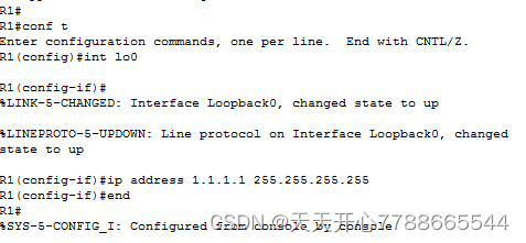
第 1 步:使用环回地址更改路由器 ID。
a.为 R1 上的 loopback 0 分配 IP 地址。
R1(config)# interface lo0
R1(config-if)# ip address 1.1.1.1 255.255.255.255
R1(config-if)# end
b.为 R2 和 R3 上的 Loopback 0 分配 IP 地址。R2 使用 IP 地址 2.2.2.2/32,R3 使用 3.3.3.3/32。
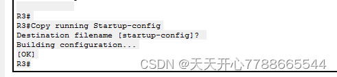
c.将运行配置保存到三台路由器的启动配置中。
d.您必须重新加载路由器,才能将路由器 ID 重置为环回地址。在三台路由器上发出 reload 命令。按 Enter 确认重新加载。
教师注意事项:clear ip ospf process 命令不能将路由器 ID 重置为环回地址。重新加载路由器会将路由器 ID 重置为环回地址。
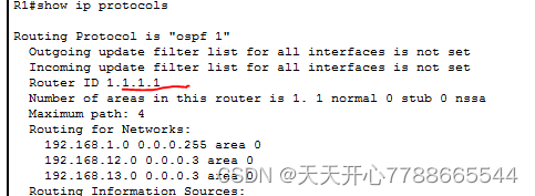
e.路由器完成重新加载过程后,发出 show ip protocols 命令查看新的路由器 ID。
R1# show ip protocols
*** IP Routing is NSF aware ***
Routing Protocol is “ospf 1”
Outgoing update filter list for all interfaces is not set
Incoming update filter list for all interfaces is not set
Router ID 1.1.1.1
Number of areas in this router is 1. 1 normal 0 stub 0 nssa
Maximum path: 4
Routing for Networks:
192.168.1.0 0.0.0.255 area 0
192.168.12.0 0.0.0.3 area 0
192.168.13.0 0.0.0.3 area 0
Routing Information Sources:
Gateway Distance Last Update
3.3.3.3 110 00:01:00
2.2.2.2 110 00:01:14
Distance: (default is 110)
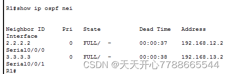
f.发出 show ip ospf neighbor 命令,以显示邻居路由器的路由器 ID 变化。
R1# show ip ospf neighbor
Neighbor ID Pri State Dead Time Address Interface
3.3.3.3 0 FULL/ - 00:00:35 192.168.13.2 Serial0/0/1
2.2.2.2 0 FULL/ - 00:00:32 192.168.12.2 Serial0/0/0
R1#
第 2 步:使用 router-id 命令更改 R1 的路由器 ID。
设置路由器 ID 的首选方法是使用 router-id 命令。
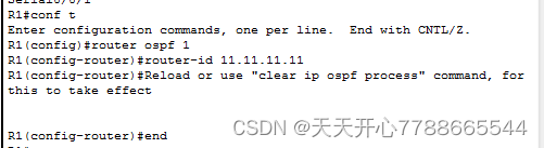
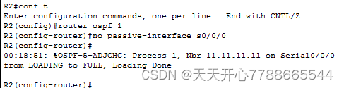
a.在 R1 上发出 router-id 11.11.11.11 命令,以重新分配路由器 ID。注意发出 router-id 命令时出现的信息性消息。
R1(config)# router ospf 1
R1(config-router)# router-id 11.11.11.11
Reload or use “clear ip ospf process” command, for this to take effect
R1(config)# end
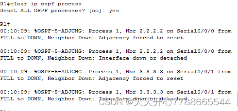
b.您将收到一条信息性消息,通知您必须重新加载路由器或使用 clear ip ospf process 命令以使更改生效。在三台路由器上发出 clear ip ospf process 命令。键入 yes 以响应重置验证消息,然后按 Enter。
c.将 R2 的路由器 ID 设置为 22.22.22.22,将 R3 的路由器 ID 设置为 33.33.33.33。然后使用 clear ip ospf process 命令重置 OSPF 路由进程。
d.发出 show ip protocols 命令,以检验 R1 的路由器 ID 是否更改。
R1# show ip protocols
*** IP Routing is NSF aware ***
Routing Protocol is “ospf 1”
Outgoing update filter list for all interfaces is not set
Incoming update filter list for all interfaces is not set
Router ID 11.11.11.11
Number of areas in this router is 1. 1 normal 0 stub 0 nssa
Maximum path: 4
Routing for Networks:
192.168.1.0 0.0.0.255 area 0
192.168.12.0 0.0.0.3 area 0
192.168.13.0 0.0.0.3 area 0
Passive Interface(s):
GigabitEthernet0/1
Routing Information Sources:
Gateway Distance Last Update
33.33.33.33 110 00:00:19
22.22.22.22 110 00:00:31
3.3.3.3 110 00:00:41
2.2.2.2 110 00:00:41
Distance: (default is 110)
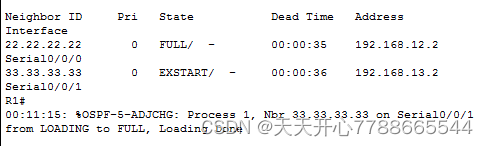
e.在 R1 上发出 show ip ospf neighbor 命令,以检验是否列出 R2 和 R3 的新路由器 ID。
R1# show ip ospf neighbor
Neighbor ID Pri State Dead Time Address Interface
33.33.33.33 0 FULL/ - 00:00:36 192.168.13.2 Serial0/0/1
22.22.22.22 0 FULL/ - 00:00:32 192.168.12.2 Serial0/0/0
第 4 部分:配置 OSPF 被动接口
passive-interface 命令用于防止路由更新通过指定路由器端口发送。因为它们不需要接收动态路由协议通信,这样做通常是为了减少 LAN 的流量。在第 4 部分,您将使用 passive-interface 命令将单个接口配置为被动接口。您还将配置 OSPF,以便路由器的所有接口在默认情况下是被动接口,然后启用选定接口的 OSPF 路由通告。
第 1 步:配置被动接口。
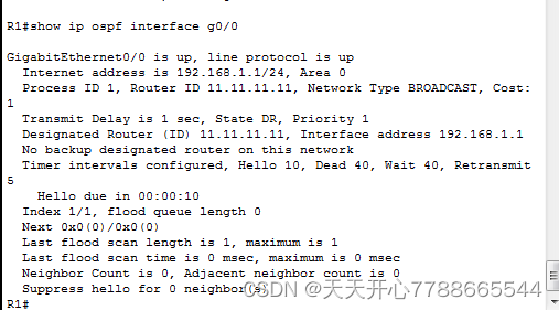
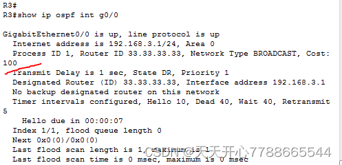
a.在 R1 上发出 show ip ospf interface g0/0 命令。请注意计时器指示下一个 hello 数据包的预期时间。Hello 数据包每 10 秒发送一次,用于在 OSPF 路由器之间检验其邻居是否已启用。
R1# show ip ospf interface g0/0
GigabitEthernet0/0 is up, line protocol is up
Internet Address 192.168.1.1/24, Area 0, Attached via Network Statement
Process ID 1, Router ID 11.11.11.11, Network Type BROADCAST, Cost: 1
Topology-MTID Cost Disabled Shutdown Topology Name
0 1 no no Base
Transmit Delay is 1 sec, State DR, Priority 1
Designated Router (ID) 11.11.11.11, Interface address 192.168.1.1
No backup designated router on this network
Timer intervals configured, Hello 10, Dead 40, Wait 40, Retransmit 5
oob-resync timeout 40
Hello due in 00:00:02
Supports Link-local Signaling (LLS)
Cisco NSF helper support enabled
IETF NSF helper support enabled
Index 1/1, flood queue length 0
Next 0x0(0)/0x0(0)
Last flood scan length is 0, maximum is 0
Last flood scan time is 0 msec, maximum is 0 msec
Neighbor Count is 0, Adjacent neighbor count is 0
Suppress hello for 0 neighbor(s)
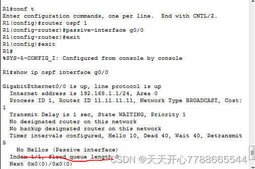
b.发出 passive-interface 命令可将 R1 上的接口 G0/0 该为被动。
R1(config)# router ospf 1
R1(config-router)# passive-interface g0/0
c.再次发出 show ip ospf interface g0/0 命令,以检验 G0/0 当前是否为被动。
R1# show ip ospf interface g0/0
GigabitEthernet0/0 is up, line protocol is up
Internet Address 192.168.1.1/24, Area 0, Attached via Network Statement
Process ID 1, Router ID 11.11.11.11, Network Type BROADCAST, Cost: 1
Topology-MTID Cost Disabled Shutdown Topology Name
0 1 no no Base
Transmit Delay is 1 sec, State DR, Priority 1
Designated Router (ID) 11.11.11.11, Interface address 192.168.1.1
No backup designated router on this network
Timer intervals configured, Hello 10, Dead 40, Wait 40, Retransmit 5
oob-resync timeout 40
No Hellos (Passive interface)
Supports Link-local Signaling (LLS)
Cisco NSF helper support enabled
IETF NSF helper support enabled
Index 1/1, flood queue length 0
Next 0x0(0)/0x0(0)
Last flood scan length is 0, maximum is 0
Last flood scan time is 0 msec, maximum is 0 msec
Neighbor Count is 0, Adjacent neighbor count is 0
Suppress hello for 0 neighbor(s)
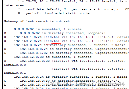
d.在 R2 和 R3 上发出 show ip route 命令,以检验到 192.168.1.0/24 网络的路由是否仍然可用。
R2# show ip route
Codes: L - local, C - connected, S - static, R - RIP, M - mobile, B - BGP
D - EIGRP, EX - EIGRP external, O - OSPF, IA - OSPF inter area
N1 - OSPF NSSA external type 1, N2 - OSPF NSSA external type 2
E1 - OSPF external type 1, E2 - OSPF external type 2
i - IS-IS, su - IS-IS summary, L1 - IS-IS level-1, L2 - IS-IS level-2
ia - IS-IS inter area, * - candidate default, U - per-user static route
o - ODR, P - periodic downloaded static route, H - NHRP, l - LISP
+ - replicated route, % - next hop override
Gateway of last resort is not set
2.0.0.0/32 is subnetted, 1 subnets
C 2.2.2.2 is directly connected, Loopback0
O 192.168.1.0/24 [110/65] via 192.168.12.1, 00:58:32, Serial0/0/0
192.168.2.0/24 is variably subnetted, 2 subnets, 2 masks
C 192.168.2.0/24 is directly connected, GigabitEthernet0/0
L 192.168.2.1/32 is directly connected, GigabitEthernet0/0
O 192.168.3.0/24 [110/65] via 192.168.23.2, 00:58:19, Serial0/0/1
192.168.12.0/24 is variably subnetted, 2 subnets, 2 masks
C 192.168.12.0/30 is directly connected, Serial0/0/0
L 192.168.12.2/32 is directly connected, Serial0/0/0
192.168.13.0/30 is subnetted, 1 subnets
O 192.168.13.0 [110/128] via 192.168.23.2, 00:58:19, Serial0/0/1
[110/128] via 192.168.12.1, 00:58:32, Serial0/0/0
192.168.23.0/24 is variably subnetted, 2 subnets, 2 masks
C 192.168.23.0/30 is directly connected, Serial0/0/1
L 192.168.23.1/32 is directly connected, Serial0/0/1
第 2 步:将被动接口设置为路由器的默认设置。
a.在 R1 上发出 show ip ospf neighbor 命令,以检验 R2 是否列为 OSPF 邻居。
R1# show ip ospf neighbor
Neighbor ID Pri State Dead Time Address Interface
33.33.33.33 0 FULL/ - 00:00:31 192.168.13.2 Serial0/0/1
22.22.22.22 0 FULL/ - 00:00:32 192.168.12.2 Serial0/0/0
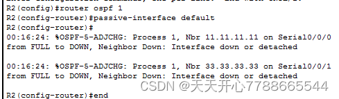
b.在 R2 上发出 passive-interface default 命令,以将所有 OSPF 接口的默认设置设为被动。
R2(config)# router ospf 1
R2(config-router)# passive-interface default
R2(config-router)#
*Apr 3 00:03:00.979: %OSPF-5-ADJCHG: Process 1, Nbr 11.11.11.11 on Serial0/0/0 from FULL to DOWN, Neighbor Down: Interface down or detached
*Apr 3 00:03:00.979: %OSPF-5-ADJCHG: Process 1, Nbr 33.33.33.33 on Serial0/0/1 from FULL to DOWN, Neighbor Down: Interface down or detached
c.在 R1 上再次发出 show ip ospf neighbor 命令。在 dead 计时器超时后,R2 不再列为 OSPF 邻居。
R1# show ip ospf neighbor
Neighbor ID Pri State Dead Time Address Interface
33.33.33.33 0 FULL/ - 00:00:34 192.168.13.2 Serial0/0/1
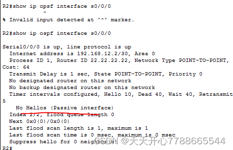
d.在 R2 上发出 show ip ospf interface S0/0/0 命令,以查看接口 S0/0/0 的 OSPF 状态。
R2# show ip ospf interface s0/0/0
Serial0/0/0 is up, line protocol is up
Internet Address 192.168.12.2/30, Area 0, Attached via Network Statement
Process ID 1, Router ID 22.22.22.22, Network Type POINT_TO_POINT, Cost: 64
Topology-MTID Cost Disabled Shutdown Topology Name
0 64 no no Base
Transmit Delay is 1 sec, State POINT_TO_POINT
Timer intervals configured, Hello 10, Dead 40, Wait 40, Retransmit 5
oob-resync timeout 40
No Hellos (Passive interface)
Supports Link-local Signaling (LLS)
Cisco NSF helper support enabled
IETF NSF helper support enabled
Index 2/2, flood queue length 0
Next 0x0(0)/0x0(0)
Last flood scan length is 0, maximum is 0
Last flood scan time is 0 msec, maximum is 0 msec
Neighbor Count is 0, Adjacent neighbor count is 0
Suppress hello for 0 neighbor(s)
e.如果 R2 上的所有接口都是被动接口,则不通告任何路由信息。在此例中,R1 和 R3 应该不再存在通向 192.168.2.0/24 网络的路由。使用 show ip route 命令可以检验这一点。
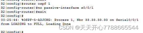
f.在 R2 上发出 no passive-interface 命令,这样路由器将发送和接收 OSPF 路由更新。输入该命令后,您将看到一条信息性消息,指示已与 R1 建立邻接关系。
R2(config)# router ospf 1
R2(config-router)# no passive-interface s0/0/0
R2(config-router)#
*Apr 3 00:18:03.463: %OSPF-5-ADJCHG: Process 1, Nbr 11.11.11.11 on Serial0/0/0 from LOADING to FULL, Loading Done
g.在 R1 和 R3 上再次发出 show ip route 和 show ipv6 ospf neighbor 命令,并查找通往 192.168.2.0/24 网络的路由。
O 192.168.2.0/24 [110/129] via 192.168.13.1, 00:00:04, Serial0/0/0
R3 使用哪个接口路由到 192.168.2.0/24 网络?Serial0/0/0
R3 上 192.168.2.0/24 网络的累计开销度量是多少?129
R2 是否显示为 R1 的 OSPF 邻居?是
R2 是否显示为 R3 的 OSPF 邻居?不是
此信息说明什么?
走度量值近的路由
h.更改 R2 上的接口 S0/0/1,以允许它通告 OSPF 路由。在下面记录使用的命令。
R2(config)# router ospf 1
R2(config-router)# no passive-interface s0/0/1
i.在 R3 上再次发出 show ip route 命令。
O 192.168.2.0/24 [110/65] via 192.168.23.1, 00:00:00, Serial0/0/1
R3 使用哪个接口路由到 192.168.2.0/24 网络?S0/0/1
现在 R3 上 192.168.2.0/24 网络的累计开销度量是多少?如何计算?
R2 是否列为 R3 的 OSPF 邻居?是
第 5 部分:更改 OSPF 度量
在第 3 部分,您将使用 auto-cost reference-bandwidth 命令、bandwidth 命令和 ip ospf cost 命令更改 OSPF 度量。
注意:所有 DCE 接口的时钟速率应在第 1 部分设置为 128000。
第 1 步:更改路由器的参考带宽。
OSPF 的默认参考带宽为 100Mb/s(快速以太网速度)。但是,大部分现代基础架构设备的链路速度超过 100Mb/s。由于 OSPF 开销度量必须是一个整数,因此传输速度等于或大于 100Mb/s 的链路的开销均为 1。这会使快速以太网、千兆以太网及 10 千兆以太网接口具有相同的开销。因此,参考带宽必须更改为更高的值,才能容纳链路速度大于 100Mb/s 的网络。
a.在 R1 上发出 show interface 命令,以查看 G0/0 接口的默认带宽设置。
R1# show interface g0/0
GigabitEthernet0/0 is up, line protocol is up
Hardware is CN Gigabit Ethernet, address is c471.fe45.7520 (bia c471.fe45.7520)
MTU 1500 bytes, BW 1000000 Kbit/sec, DLY 100 usec,
reliability 255/255, txload 1/255, rxload 1/255
Encapsulation ARPA, loopback not set
Keepalive set (10 sec)
Full Duplex, 100Mbps, media type is RJ45
output flow-control is unsupported, input flow-control is unsupported
ARP type: ARPA, ARP Timeout 04:00:00
Last input never, output 00:17:31, output hang never
Last clearing of “show interface” counters never
Input queue: 0/75/0/0 (size/max/drops/flushes); Total output drops: 0
Queueing strategy: fifo
Output queue: 0/40 (size/max)
5 minute input rate 0 bits/sec, 0 packets/sec
5 minute output rate 0 bits/sec, 0 packets/sec
0 packets input, 0 bytes, 0 no buffer
Received 0 broadcasts (0 IP multicasts)
0 runts, 0 giants, 0 throttles
0 input errors, 0 CRC, 0 frame, 0 overrun, 0 ignored
0 watchdog, 0 multicast, 0 pause input
279 packets output, 89865 bytes, 0 underruns
0 output errors, 0 collisions, 1 interface resets
0 unknown protocol drops
0 babbles, 0 late collision, 0 deferred
1 lost carrier, 0 no carrier, 0 pause output
0 output buffer failures, 0 output buffers swapped out
注意:如果 PC 主机接口只能支持快速以太网速度,G0/0 的带宽设置可能与如上所示有所差异。如果 PC 主机接口不支持千兆速度,则带宽很可能会显示为 100000 Kbit/sec。
b.在 R1 上发出 show ip route ospf 命令,以确定到 192.168.3.0/24 网络的路由。
R1# show ip route ospf
Codes: L - local, C - connected, S - static, R - RIP, M - mobile, B - BGP
D - EIGRP, EX - EIGRP external, O - OSPF, IA - OSPF inter area
N1 - OSPF NSSA external type 1, N2 - OSPF NSSA external type 2
E1 - OSPF external type 1, E2 - OSPF external type 2
i - IS-IS, su - IS-IS summary, L1 - IS-IS level-1, L2 - IS-IS level-2
ia - IS-IS inter area, * - candidate default, U - per-user static route
o - ODR, P - periodic downloaded static route, H - NHRP, l - LISP
+ - replicated route, % - next hop override
Gateway of last resort is not set
O 192.168.3.0/24 [110/65] via 192.168.13.2, 00:00:57, Serial0/0/1
192.168.23.0/30 is subnetted, 1 subnets
O 192.168.23.0 [110/128] via 192.168.13.2, 00:00:57, Serial0/0/1
[110/128] via 192.168.12.2, 00:01:08, Serial0/0/0
注意:从 R1 到 192.168.3.0/24 网络的累计开销为 65。
c.在 R3 上发出 show ip ospf interface 命令,以确定 G0/0 的路由开销。
R3# show ip ospf interface g0/0
GigabitEthernet0/0 is up, line protocol is up
Internet Address 192.168.3.1/24, Area 0, Attached via Network Statement
Process ID 1, Router ID 3.3.3.3, Network Type BROADCAST, Cost: 1
Topology-MTID Cost Disabled Shutdown Topology Name
0 1 no no Base
Transmit Delay is 1 sec, State DR, Priority 1
Designated Router (ID) 192.168.23.2, Interface address 192.168.3.1
No backup designated router on this network
Timer intervals configured, Hello 10, Dead 40, Wait 40, Retransmit 5
oob-resync timeout 40
Hello due in 00:00:05
Supports Link-local Signaling (LLS)
Cisco NSF helper support enabled
IETF NSF helper support enabled
Index 1/1, flood queue length 0
Next 0x0(0)/0x0(0)
Last flood scan length is 0, maximum is 0
Last flood scan time is 0 msec, maximum is 0 msec
Neighbor Count is 0, Adjacent neighbor count is 0
Suppress hello for 0 neighbor(s)
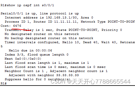
d.在 R1 上发出 show ip ospf interface s0/0/1 命令,以查看 S0/0/1 的路由开销。
R1# show ip ospf interface s0/0/1
Serial0/0/1 is up, line protocol is up
Internet Address 192.168.13.1/30, Area 0, Attached via Network Statement
Process ID 1, Router ID 1.1.1.1, Network Type POINT_TO_POINT, Cost: 64
Topology-MTID Cost Disabled Shutdown Topology Name
0 64 no no Base
Transmit Delay is 1 sec, State POINT_TO_POINT
Timer intervals configured, Hello 10, Dead 40, Wait 40, Retransmit 5
oob-resync timeout 40
Hello due in 00:00:04
Supports Link-local Signaling (LLS)
Cisco NSF helper support enabled
IETF NSF helper support enabled
Index 3/3, flood queue length 0
Next 0x0(0)/0x0(0)
Last flood scan length is 1, maximum is 1
Last flood scan time is 0 msec, maximum is 0 msec
Neighbor Count is 1, Adjacent neighbor count is 1
Adjacent with neighbor 192.168.23.2
Suppress hello for 0 neighbor(s)
从 show ip route 命令的输出可以看出,这两个接口的开销总和是 R3 上到 192.168.3.0/24 网络的路由的累计开销 (1 + 64 = 65)。
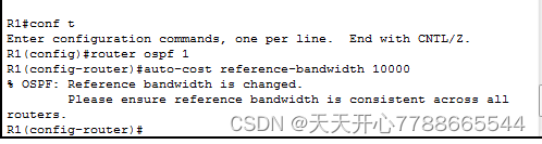
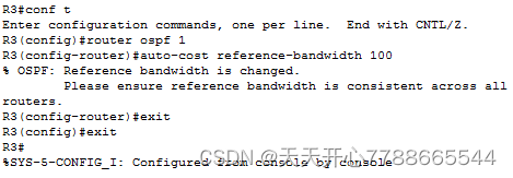
e.在 R1 上发出 auto-cost reference-bandwidth 10000 命令,以更改默认的参考带宽设置。通过这样设置,10Gb/s 接口的开销为 1,1Gb/s 接口的开销为 10,100Mb/s 接口的开销为 100。
R1(config)# router ospf 1
R1(config-router)# auto-cost reference-bandwidth 10000
% OSPF: Reference bandwidth is changed.
Please ensure reference bandwidth is consistent across all routers.
f.在路由器 R2 和 R3 上发出 auto-cost reference-bandwidth 10000 命令。
g.再次发出 show ip ospf interface 命令,以查看 R3 上 G0/0 的新开销和 R1 上 S0/0/1 的新开销。
R3# show ip ospf interface g0/0
GigabitEthernet0/0 is up, line protocol is up
Internet Address 192.168.3.1/24, Area 0, Attached via Network Statement
Process ID 1, Router ID 3.3.3.3, Network Type BROADCAST, Cost: 10
Topology-MTID Cost Disabled Shutdown Topology Name
0 10 no no Base
Transmit Delay is 1 sec, State DR, Priority 1
Designated Router (ID) 192.168.23.2, Interface address 192.168.3.1
No backup designated router on this network
Timer intervals configured, Hello 10, Dead 40, Wait 40, Retransmit 5
oob-resync timeout 40
Hello due in 00:00:02
Supports Link-local Signaling (LLS)
Cisco NSF helper support enabled
IETF NSF helper support enabled
Index 1/1, flood queue length 0
Next 0x0(0)/0x0(0)
Last flood scan length is 0, maximum is 0
Last flood scan time is 0 msec, maximum is 0 msec
Neighbor Count is 0, Adjacent neighbor count is 0
Suppress hello for 0 neighbor(s)
注意:如果连接到 G0/0 接口的设备不支持千兆以太网速度,则开销与输出显示不同。例如,快速以太网速度 (100Mb/s) 的开销为 100。
R1# show ip ospf interface s0/0/1
Serial0/0/1 is up, line protocol is up
Internet Address 192.168.13.1/30, Area 0, Attached via Network Statement
Process ID 1, Router ID 1.1.1.1, Network Type POINT_TO_POINT, Cost: 6476
Topology-MTID Cost Disabled Shutdown Topology Name
0 6476 no no Base
Transmit Delay is 1 sec, State POINT_TO_POINT
Timer intervals configured, Hello 10, Dead 40, Wait 40, Retransmit 5
oob-resync timeout 40
Hello due in 00:00:05
Supports Link-local Signaling (LLS)
Cisco NSF helper support enabled
IETF NSF helper support enabled
Index 3/3, flood queue length 0
Next 0x0(0)/0x0(0)
Last flood scan length is 1, maximum is 1
Last flood scan time is 0 msec, maximum is 0 msec
Neighbor Count is 1, Adjacent neighbor count is 1
Adjacent with neighbor 192.168.23.2
Suppress hello for 0 neighbor(s)
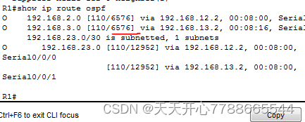
h.再次发出 show ip route ospf 命令,以查看 192.168.3.0/24 路由的新累计开销 (10 + 6476 = 6486)。
注意:如果连接到 G0/0 接口的设备不支持千兆以太网速度,则总开销与输出显示不同。例如,如果 G0/0 以快速以太网速度 (100Mb/s) 运行,则累计开销为 6576。
R1# show ip route ospf
Codes: L - local, C - connected, S - static, R - RIP, M - mobile, B - BGP
D - EIGRP, EX - EIGRP external, O - OSPF, IA - OSPF inter area
N1 - OSPF NSSA external type 1, N2 - OSPF NSSA external type 2
E1 - OSPF external type 1, E2 - OSPF external type 2
i - IS-IS, su - IS-IS summary, L1 - IS-IS level-1, L2 - IS-IS level-2
ia - IS-IS inter area, * - candidate default, U - per-user static route
o - ODR, P - periodic downloaded static route, H - NHRP, l - LISP
+ - replicated route, % - next hop override
Gateway of last resort is not set
O 192.168.2.0/24 [110/6486] via 192.168.12.2, 00:05:40, Serial0/0/0
O 192.168.3.0/24 [110/6486] via 192.168.13.2, 00:01:08, Serial0/0/1
192.168.23.0/30 is subnetted, 1 subnets
O 192.168.23.0 [110/12952] via 192.168.13.2, 00:05:17, Serial0/0/1
[110/12952] via 192.168.12.2, 00:05:17, Serial0/0/
注意:将路由器的默认参考带宽从 100 更改为 10,000 实际是以 100 为系数更改了所有路由的累计开销,但是现在能够更准确地反映每个接口的链路和路由开销。
i.要将参考带宽重置为其默认值,则在三台路由器上发出 auto-cost reference-bandwidth 100 命令。
R1(config)# router ospf 1
R1(config-router)# auto-cost reference-bandwidth 100
% OSPF: Reference bandwidth is changed.
Please ensure reference bandwidth is consistent across all routers.
为什么要更改 OSPF 默认参考带宽?
为了准确反映每个忌口的链路和路由开销
第 2 步:更改接口的带宽。
在大多数串行链路上,带宽度量将默认为 1544 Kbit(T1 的设置)。如果这不是串行链路的实际速度,则需要更改带宽设置以匹配实际速度,从而在 OSPF 中正确计算路由成本。使用 bandwidth 命令调整接口的带宽设置。
注意:人们通常误解 bandwidth 命令会更改链路的物理带宽或速度。该命令会修改 OSPF 计算路由开销所用的带宽度量,但不更改链路的实际带宽(速度)。
a.在 R1 上发出 show interface s0/0/0 命令,以查看 S0/0/0 的当前带宽设置。尽管该接口的时钟频率和链路速度已设置为 128Kb/s,但是带宽仍显示 1544Kb/s。
R1# show interface s0/0/0
Serial0/0/0 is up, line protocol is up
Hardware is WIC MBRD Serial
Internet address is 192.168.12.1/30
MTU 1500 bytes, BW 1544 Kbit/sec, DLY 20000 usec,
reliability 255/255, txload 1/255, rxload 1/255
Encapsulation HDLC, loopback not set
Keepalive set (10 sec)
<省略部分输出>
b.在 R1 上发出 show ip route ospf 命令,以查看使用 S0/0/0 到网络 192.168.23.0/24 的路由的累计开销。注意,到 192.168.23.0/24 网络有两个等价 (128) 路由,一个通过 S0/0/0 而另一个通过 S0/0/1。
R1# show ip route ospf
Codes: L - local, C - connected, S - static, R - RIP, M - mobile, B - BGP
D - EIGRP, EX - EIGRP external, O - OSPF, IA - OSPF inter area
N1 - OSPF NSSA external type 1, N2 - OSPF NSSA external type 2
E1 - OSPF external type 1, E2 - OSPF external type 2
i - IS-IS, su - IS-IS summary, L1 - IS-IS level-1, L2 - IS-IS level-2
ia - IS-IS inter area, * - candidate default, U - per-user static route
o - ODR, P - periodic downloaded static route, H - NHRP, l - LISP
+ - replicated route, % - next hop override
Gateway of last resort is not set
O 192.168.3.0/24 [110/65] via 192.168.13.2, 00:00:26, Serial0/0/1
192.168.23.0/30 is subnetted, 1 subnets
O 192.168.23.0 [110/128] via 192.168.13.2, 00:00:26, Serial0/0/1
[110/128] via 192.168.12.2, 00:00:42, Serial0/0/0
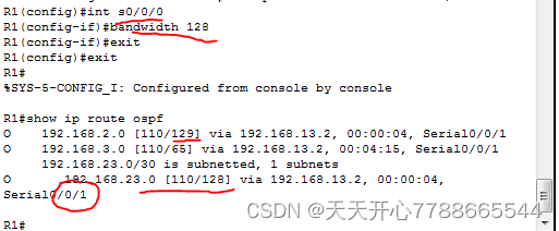
c.发出 bandwidth 128 命令,以将 S0/0/0 接口的带宽设置为 128Kb/s。
R1(config)# interface s0/0/0
R1(config-if)# bandwidth 128
d.再次发出 show ip route ospf 命令。路由表不再显示通过 S0/0/0 接口到达 192.168.23.0/24 网络的路由。这是因为最佳路由(即开销最低的路由)现在是通过 S0/0/1。
R1# show ip route ospf
Codes: L - local, C - connected, S - static, R - RIP, M - mobile, B - BGP
D - EIGRP, EX - EIGRP external, O - OSPF, IA - OSPF inter area
N1 - OSPF NSSA external type 1, N2 - OSPF NSSA external type 2
E1 - OSPF external type 1, E2 - OSPF external type 2
i - IS-IS, su - IS-IS summary, L1 - IS-IS level-1, L2 - IS-IS level-2
ia - IS-IS inter area, * - candidate default, U - per-user static route
o - ODR, P - periodic downloaded static route, H - NHRP, l - LISP
+ - replicated route, % - next hop override
Gateway of last resort is not set
O 192.168.3.0/24 [110/65] via 192.168.13.2, 00:04:51, Serial0/0/1
192.168.23.0/30 is subnetted, 1 subnets
O 192.168.23.0 [110/128] via 192.168.13.2, 00:04:51, Serial0/0/1
e.发出 show ip ospf interface brief 命令。S0/0/0 的开销从 64 更改为 781,它表示链路速度的准确开销。
R1# show ip ospf interface brief
Interface PID Area IP Address/Mask Cost State Nbrs F/C
Se0/0/1 1 0 192.168.13.1/30 64 P2P 1/1
Se0/0/0 1 0 192.168.12.1/30 781 P2P 1/1
Gi0/0 1 0 192.168.1.1/24 1 DR 0/0
f.将接口 S0/0/1 的带宽设置为与 R1 上 S0/0/0 相同的设置。
R1(config)# interface s0/0/1
R1(config-if)# bandwidth 128
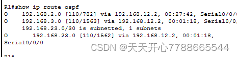
g.再次发出 show ip route ospf 命令,以查看两条路由到 192.168.23.0/24 网络的累计开销。注意,到 192.168.23.0/24 网络仍有两个等价 (845) 路由,一个通过 S0/0/0 而另一个通过 S0/0/1。
R1# show ip route ospf
Codes: L - local, C - connected, S - static, R - RIP, M - mobile, B - BGP
D - EIGRP, EX - EIGRP external, O - OSPF, IA - OSPF inter area
N1 - OSPF NSSA external type 1, N2 - OSPF NSSA external type 2
E1 - OSPF external type 1, E2 - OSPF external type 2
i - IS-IS, su - IS-IS summary, L1 - IS-IS level-1, L2 - IS-IS level-2
ia - IS-IS inter area, * - candidate default, U - per-user static route
o - ODR, P - periodic downloaded static route, H - NHRP, l - LISP
+ - replicated route, % - next hop override
Gateway of last resort is not set
O 192.168.3.0/24 [110/782] via 192.168.13.2, 00:00:09, Serial0/0/1
192.168.23.0/30 is subnetted, 1 subnets
O 192.168.23.0 [110/845] via 192.168.13.2, 00:00:09, Serial0/0/1
[110/845] via 192.168.12.2, 00:00:09, Serial0/0/0
解释如何计算从 R1 到 192.168.3.0/24 和 192.168.23.0/30 网络的开销。
、
192.168.3.0/24 _的开销782= costg0/0+costs0/0/1=1+781
_192.168.23.0/30的开销为R3 costs0/0/1+R1s0/0/1=781+64=845
h.在 R3 上发出 show ip route ospf 命令。192.168.1.0/24 的累计开销仍显示为 65。不同于 clock rate 命令,bandwidth 命令要应用于串行链路的两端。
R3# show ip route ospf
Codes: L - local, C - connected, S - static, R - RIP, M - mobile, B - BGP
D - EIGRP, EX - EIGRP external, O - OSPF, IA - OSPF inter area
N1 - OSPF NSSA external type 1, N2 - OSPF NSSA external type 2
E1 - OSPF external type 1, E2 - OSPF external type 2
i - IS-IS, su - IS-IS summary, L1 - IS-IS level-1, L2 - IS-IS level-2
ia - IS-IS inter area, * - candidate default, U - per-user static route
o - ODR, P - periodic downloaded static route, H - NHRP, l - LISP
+ - replicated route, % - next hop override
Gateway of last resort is not set
O 192.168.1.0/24 [110/65] via 192.168.13.1, 00:30:58, Serial0/0/0
192.168.12.0/30 is subnetted, 1 subnets
O 192.168.12.0 [110/128] via 192.168.23.1, 00:30:58, Serial0/0/1
[110/128] via 192.168.13.1, 00:30:58, Serial0/0/0
i.对拓扑结构中的所有其余串行接口发出 bandwidth 128 命令。
R1 上 192.168.23.0/24 网络的新累计开销是多少?为什么?
1562=781+781
第 3 步:更改路由开销。
默认情况下,OSPF 使用带宽设置计算链路的开销。但是,您可以使用 ip ospf cost 命令手动设置链路开销来覆盖该计算。和 bandwidth 命令一样,ip ospf cost 命令只影响应用了命令的链路端。
a.在 R1 上发出 show ip route ospf 命令。
R1# show ip route ospf
Codes: L - local, C - connected, S - static, R - RIP, M - mobile, B - BGP
D - EIGRP, EX - EIGRP external, O - OSPF, IA - OSPF inter area
N1 - OSPF NSSA external type 1, N2 - OSPF NSSA external type 2
E1 - OSPF external type 1, E2 - OSPF external type 2
i - IS-IS, su - IS-IS summary, L1 - IS-IS level-1, L2 - IS-IS level-2
ia - IS-IS inter area, * - candidate default, U - per-user static route
o - ODR, P - periodic downloaded static route, H - NHRP, l - LISP
+ - replicated route, % - next hop override
Gateway of last resort is not set
O 192.168.2.0/24 [110/782] via 192.168.12.2, 00:00:26, Serial0/0/0
O 192.168.3.0/24 [110/782] via 192.168.13.2, 00:02:50, Serial0/0/1
192.168.23.0/30 is subnetted, 1 subnets
O 192.168.23.0 [110/1562] via 192.168.13.2, 00:02:40, Serial0/0/1
[110/1562] via 192.168.12.2, 00:02:40, Serial0/0/0
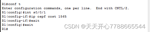
b.对 R1 上的 S0/0/1 接口应用 ip ospf cost 1565 命令。开销 1565 高于通过 R2 的累计路由开销 1562。
R1(config)# int s0/0/1
R1(config-if)# ip ospf cost 1565
c.在 R1 上再次发出 show ip route ospf 命令,以显示此更改对路由表的作用。R1 的所有 OSPF 路由现在将通过 R2 路由。
R1# show ip route ospf
Codes: L - local, C - connected, S - static, R - RIP, M - mobile, B - BGP
D - EIGRP, EX - EIGRP external, O - OSPF, IA - OSPF inter area
N1 - OSPF NSSA external type 1, N2 - OSPF NSSA external type 2
E1 - OSPF external type 1, E2 - OSPF external type 2
i - IS-IS, su - IS-IS summary, L1 - IS-IS level-1, L2 - IS-IS level-2
ia - IS-IS inter area, * - candidate default, U - per-user static route
o - ODR, P - periodic downloaded static route, H - NHRP, l - LISP
+ - replicated route, % - next hop override
Gateway of last resort is not set
O 192.168.2.0/24 [110/782] via 192.168.12.2, 00:02:06, Serial0/0/0
O 192.168.3.0/24 [110/1563] via 192.168.12.2, 00:05:31, Serial0/0/0
192.168.23.0/30 is subnetted, 1 subnets
O 192.168.23.0 [110/1562] via 192.168.12.2, 01:14:02, Serial0/0/0
注意:使用 ip ospf cost 命令控制链路开销是更改 OSPF 路由开销最容易的首选方式。除了根据带宽更改开销之外,网络管理员可能还会出于其他原因更改路由开销,例如对特定服务提供商的偏好,或者链路或路由的实际资金成本等。
解释 R1 上到 192.168.3.0/24 网络的路由为什么现在通过 R2 路由?
之前的开销被设置为1563比走r21562开销大,所以不走了
思考
1.在使用 OSPF 协议时,为什么控制路由器 ID 分配很重要?
域内唯一标识,没有这个无法区分是否在同意区域内
2.为什么本实验不考虑 DR/BDR 选举过程?
只有广播才会选举DR,DR是针对某个文段的概念,对于路由器接口而言,一个接口是DR.另一个是BDR DR Other 若选择完毕后,加入一台新路由器即使dr优先级最大也不会立即称为该网段中的dr,dr不一定就是dr优先足底啊的路由器,同理,bdr也并不一定是DR优先级第二的路由器
3.为什么要将 OSPF 接口设置为被动?
防止路由更新通过指定路由器端口发送,他们用不到接收动态路由协议通信,减少LAN的流量,使用passive-interface 命令配置为被动接口 然后配置OSPF,以便路由器的所有接口在默认情况下是被动接口,然后启用在选定接口的ospf路由通告
路由器接口摘要表
路由器接口摘要
路由器型号 Ethernet Interface #1 Ethernet Interface #2 Serial Interface #1 Serial Interface #2
1800 Fast Ethernet 0/0 (F0/0) Fast Ethernet 0/1 (F0/1) Serial 0/0/0 (S0/0/0) Serial 0/0/1 (S0/0/1)
1900 Gigabit Ethernet 0/0 (G0/0) Gigabit Ethernet 0/1 (G0/1) Serial 0/0/0 (S0/0/0) Serial 0/0/1 (S0/0/1)
2801 Fast Ethernet 0/0 (F0/0) Fast Ethernet 0/1 (F0/1) Serial 0/1/0 (S0/1/0) Serial 0/1/1 (S0/1/1)
2811 Fast Ethernet 0/0 (F0/0) Fast Ethernet 0/1 (F0/1) Serial 0/0/0 (S0/0/0) Serial 0/0/1 (S0/0/1)
2900 Gigabit Ethernet 0/0 (G0/0) Gigabit Ethernet 0/1 (G0/1) Serial 0/0/0 (S0/0/0) Serial 0/0/1 (S0/0/1)
注意:若要了解如何配置路由器,请查看接口来确定路由器类型以及路由器拥有的接口数量。我们无法为每类路由器列出所有的配置组合。下表列出了设备中以太网和串行接口组合的标识符。此表中未包含任何其他类型的接口,但实际的路由器可能会含有其他接口。例如 ISDN BRI 接口。括号中的字符串是约定缩写,可在 Cisco IOS 命令中用来代表接口。
设备配置 - 最后部分
路由器 R1
R1#sh run
Building configuration…
Current configuration : 1794 bytes
!
version 15.2
service timestamps debug datetime msec
service timestamps log datetime msec
no service password-encryption
!
hostname R1
!
boot-start-marker
boot-end-marker
!
!
enable secret 4 06YFDUHH61wAE/kLkDq9BGho1QM5EnRtoyr8cHAUg.2
!
no aaa new-model
memory-size iomem 15
!
no ip domain lookup
ip cef
no ipv6 cef
multilink bundle-name authenticated
!
interface Loopback0
ip address 1.1.1.1 255.255.255.255
!
interface Embedded-Service-Engine0/0
no ip address
shutdown
!
interface GigabitEthernet0/0
ip address 192.168.1.1 255.255.255.0
duplex auto
speed auto
!
interface GigabitEthernet0/1
no ip address
shutdown
duplex auto
speed auto
!
interface Serial0/0/0
bandwidth 128
ip address 192.168.12.1 255.255.255.252
clock rate 128000
!
interface Serial0/0/1
bandwidth 128
ip address 192.168.13.1 255.255.255.252
ip ospf cost 1565
!
router ospf 1
router-id 11.11.11.11
passive-interface GigabitEthernet0/0
network 192.168.1.0 0.0.0.255 area 0
network 192.168.12.0 0.0.0.3 area 0
network 192.168.13.0 0.0.0.3 area 0
!
ip forward-protocol nd
!
no ip http server
no ip http secure-server
!
control-plane
!
!
banner motd ^C
Unauthorized Access is Prohibited!
^C
!
line con 0
password cisco
logging synchronous
login
line aux 0
line 2
no activation-character
no exec
transport preferred none
transport input all
transport output pad telnet rlogin lapb-ta mop udptn v120 ssh
stopbits 1
line vty 0
password cisco
login
transport input all
line vty 1 4
login
transport input all
!
scheduler allocate 20000 1000
!
end
路由器 R2
R2#sh run
Building configuration…
Current configuration : 1912 bytes
!
version 15.2
service timestamps debug datetime msec
service timestamps log datetime msec
no service password-encryption
!
hostname R2
!
boot-start-marker
boot-end-marker
!
enable secret 4 06YFDUHH61wAE/kLkDq9BGho1QM5EnRtoyr8cHAUg.2
!
no aaa new-model
memory-size iomem 15
!
no ip domain lookup
ip cef
no ipv6 cef
multilink bundle-name authenticated
!
interface Loopback0
ip address 2.2.2.2 255.255.255.255
!
interface Embedded-Service-Engine0/0
no ip address
shutdown
!
interface GigabitEthernet0/0
ip address 192.168.2.1 255.255.255.0
duplex auto
speed auto
!
interface GigabitEthernet0/1
no ip address
shutdown
duplex auto
speed auto
!
interface Serial0/0/0
bandwidth 128
ip address 192.168.12.2 255.255.255.252
!
interface Serial0/0/1
bandwidth 128
ip address 192.168.23.1 255.255.255.252
clock rate 128000
!
router ospf 1
router-id 22.22.22.22
passive-interface default
no passive-interface Serial0/0/0
no passive-interface Serial0/0/1
network 192.168.2.0 0.0.0.255 area 0
network 192.168.12.0 0.0.0.3 area 0
network 192.168.23.0 0.0.0.3 area 0
!
ip forward-protocol nd
!
no ip http server
no ip http secure-server
!
control-plane
!
banner motd ^C
Unauthorized Access is Prohibited!
^C
!
line con 0
password cisco
logging synchronous
login
line aux 0
line 2
no activation-character
no exec
transport preferred none
transport input all
transport output pad telnet rlogin lapb-ta mop udptn v120 ssh
stopbits 1
line vty 0
password cisco
login
transport input all
line vty 1 4
login
transport input all
!
scheduler allocate 20000 1000
!
end
路由器 R3
R3#sh run
Building configuration…
Current configuration : 1674 bytes
!
version 15.2
service timestamps debug datetime msec
service timestamps log datetime msec
no service password-encryption
!
hostname R3
!
boot-start-marker
boot-end-marker
!
enable secret 4 06YFDUHH61wAE/kLkDq9BGho1QM5EnRtoyr8cHAUg.2
!
no aaa new-model
memory-size iomem 10
!
no ip domain lookup
ip cef
no ipv6 cef
multilink bundle-name authenticated
!
interface Loopback0
ip address 3.3.3.3 255.255.255.255
!
interface Embedded-Service-Engine0/0
no ip address
shutdown
!
interface GigabitEthernet0/0
ip address 192.168.3.1 255.255.255.0
duplex auto
speed auto
!
interface GigabitEthernet0/1
no ip address
shutdown
duplex auto
speed auto
!
interface Serial0/0/0
bandwidth 128
ip address 192.168.13.2 255.255.255.252
clock rate 128000
!
interface Serial0/0/1
bandwidth 128
ip address 192.168.23.2 255.255.255.252
!
router ospf 1
router-id 33.33.33.33
network 192.168.3.0 0.0.0.255 area 0
network 192.168.13.0 0.0.0.3 area 0
network 192.168.23.0 0.0.0.3 area 0
!
ip forward-protocol nd
!
no ip http server
no ip http secure-server
!
control-plane
!
banner motd ^C
Unauthorized Access is Prohibited!
^C
!
line con 0
password cisco
logging synchronous
login
line aux 0
line 2
no activation-character
no exec
transport preferred none
transport input all
transport output pad telnet rlogin lapb-ta mop udptn v120 ssh
stopbits 1
line vty 0 4
password cisco
login
transport input all
!
scheduler allocate 20000 1000
!
end
步骤图
第一步:配置pc机的ip地址和网关
(配置一个,其余两个一样)
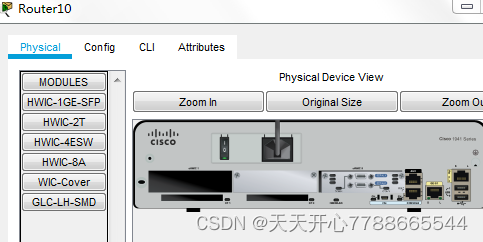
第二步:配置路由器的串口,关闭电源,放入串口,再打开电源,三个一样,并且连接如图二所示

第三步:配置路由器(只配一个,剩余的两个自己重复)
a.禁用 DNS 查找。
b.如拓扑所示配置设备名称。
c.指定 class 为特权 EXEC 密码。
d.指定 cisco 为控制台密码和 vty 密码。
e.配置一个向用户发出警告的当日消息 (MOTD) 标语:未经授权,禁止访问。
f.为控制台线路配置 logging synchronous。
g.在所有接口上配置地址分配表中列出的地址。
h.将所有 DCE 串行接口的时钟频率设置为 128000。
i.将运行配置复制到启动配置。

完成后的拓扑图如下:
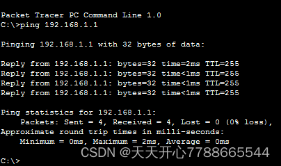
第四步:测试连通性
pc机与直连路由器之间互相ping
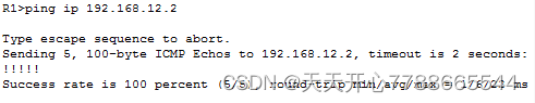
R1路由器与R2路由器之间互相ping
第五步:在R1 R2 R3配置opsf路由(其他两个自己重复,network只是把对应接口ip地址的最后一位改成0就好 且子网掩码为反码 且一个路由器设置一个area)
第六步:检验OSPF 的邻居信息 show ip ospf neighbor
第七步:show ip route 检查路由表中的信息是否全
(只查看ospf路由是 show ip route ospf)
第八步:检验ospf协议设置show ip protocols
第九步:检验ospf进程信息show ip ospf
第十步:
pca检测能否pingbc
第十一步:使用换回地址更改路由器id(三个都要做,只做一个)
保存设置
输入reload重置环回地址
第十二步:show ip protocols 命令查看新的路由器 ID
发出 show ip ospf neighbor 命令,以显示邻居路由器的路由器 ID 变化
第十三步:使用 router-id 命令更改 R1 2 3 的路由器 ID(只做一个)
第十四步:展示邻居路由
第十五步:配置ospf被动接口
第十六步:b.在 R2 上发出 passive-interface default 命令,以将所有 OSPF 接口的默认设置设为被动。
第十七步:在 R2 上发出 no passive-interface 命令,这样路由器将发送和接收 OSPF 路由更新。输入该命令后,您将看到一条信息性消息,指示已与 R1 建立邻接关系
第十八步:g.在 R1 和 R3 上再次发出 show ip route 命令,并查找通往 192.168.2.0/24 网络的路由。
R1: 192.168.2.0/24 [110/65] via 192.168.12.2, 00:01:20, Serial0/0/0
R:3:192.168.2.0/24 [110/129] via 192.168.13.1, 00:02:25, Serial0/0/0
第十九步:更改 R2 上的接口 S0/0/1,以允许它通告 OSPF 路由
r3的路由表到该网络视是0/0/1 这个度量值是65,ospf起作用了走度量值小的路线
第二十步:分别查看r1和r3 show ip route ospf 发现度量值都是65
单独对接口查看是64 说明接口占1个度量值
第二十一步:在 R1 2 3上发出 auto-cost reference-bandwidth 10000 命令,以更改默认的参考带宽设置(操作一样只做一个)
第二十二步:查看r3的g0/0接口
第二十三步:查看r3的s0/0/1接口和总路由
第二十四步:要将三个路由器参考带宽重置为其默认值(重复操作,只做一个)
第二十五步:修改r1 s/0/0/0接口的带宽,此时到达192.168.23.0的最小开销是128走 s0/0/1 了
第二十六步:f.将接口 S0/0/1 的带宽设置为与 R1 上 S0/0/0 相同的设置(与上图相同 不做了)
第二十七步:讲R2 3 串行接口两端都设置为最小开销128,不重复了
第二十八步:对 R1 上的 S0/0/1 接口应用 ip ospf cost 1565,在 R1 上再次发出 show ip route ospf 命令,以显示此更改对路由表的作用


 3901
3901


 被折叠的 条评论
为什么被折叠?
被折叠的 条评论
为什么被折叠?
 到【灌水乐园】发言


