


基于STM32的健康监测系统设计
摘要
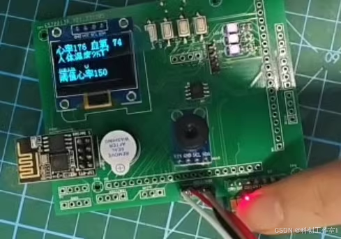
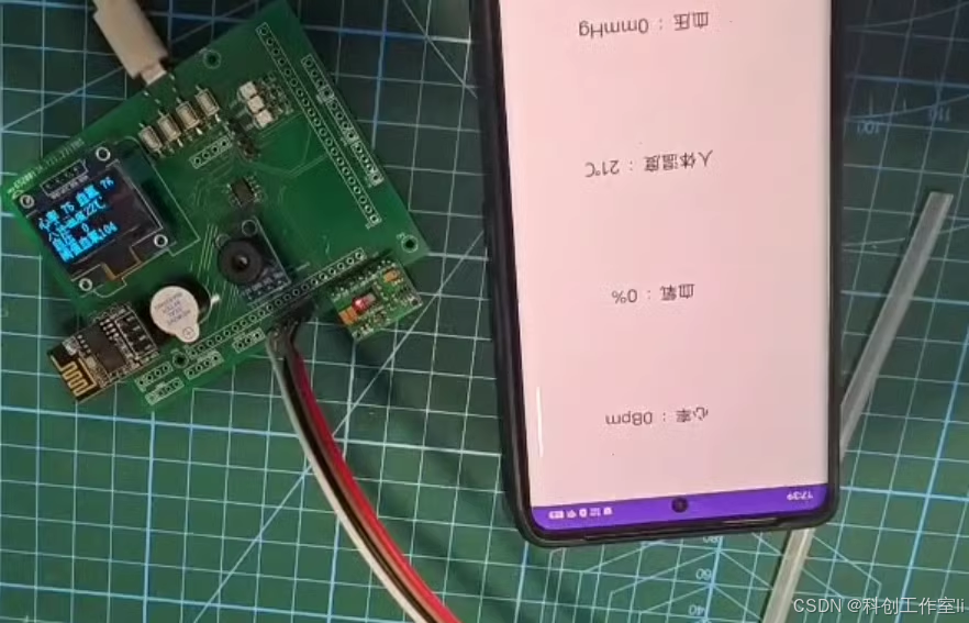
随着现代生活节奏的加快,个人健康管理已成为人们关注的焦点。传统的健康监测方式依赖于医疗设备或定期体检,存在监测周期长、数据不连续等问题。本文设计了一款基于STM32的智能健康监测系统,该系统采用STM32F103C8T6作为主控芯片,结合MAX30102心率血氧传感器、GY-906红外温度传感器、XGZP6847A气压传感器以及OLED显示屏等模块,实现了对人体心率/脉搏、血氧、体温及模拟血压的实时监测,并通过WiFi将数据实时传送到手机APP中进行远程监测。系统还具备按键调整阈值及声光报警功能,为用户提供了全面的健康管理方案。
关键词
STM32;健康监测;MAX30102心率血氧传感器;GY-906红外温度传感器;XGZP6847A气压传感器;OLED显示屏;WiFi远程监测
引言
随着科技的飞速发展,个人健康管理已经逐渐从传统的医疗设备监测转向智能化、便携化的方向。智能化健康监测系统通过实时监测人体各项生理参数,能够为用户提供及时的健康预警和数据分析,从而帮助用户更好地了解自己的健康状况。基于STM32的微控制器因其高性能、低功耗和易于开发等特点,在智能化健康监测系统中得到了广泛应用。
本文旨在设计一款基于STM32的智能健康监测系统,该系统能够实时监测人体的心率/脉搏、血氧、体温及模拟血压等关键生理参数,并通过OLED显示屏进行直观显示。同时,系统还支持WiFi远程监测功能,用户可以通过手机APP实时查看各项监测数据。此外,系统还具备按键调整阈值及声光报警功能,当监测数据超出设定阈值时,系统将自动报警,提醒用户注意。
一、系统设计
1.1 系统架构
本系统以STM32F103C8T6单片机为核心,结合多种传感器模块、显示模块、无线通信模块及按键模块,构建了完整的智能健康监测系统。系统架构如图1所示。
图1 系统架构图
1.2 主控芯片
STM32F103C8T6是一款基于ARM Cortex-M3内核的32位微控制器,具有高性能、低功耗、易于开发等优点。本系统采用STM32F103C8T6作为主控芯片,负责系统的数据处理和控制逻辑。该芯片具有丰富的外设接口,包括USART、I2C、SPI等,方便与其他模块进行通信。
1.3 传感器模块
1.3.1 MAX30102心率血氧传感器
MAX30102是一款高性能的生物传感器模块,能够实时、准确地测量人体的血氧饱和度和心率等重要生理参数。该模块采用光电容积脉搏波描记法(PPG)原理工作,通过发射特定波长的红光和红外光,照射人体组织,然后检测经过人体组织反射或透射后的光信号强度变化,从而计算出血氧饱和度和心率。本系统采用MAX30102心率血氧传感器采集用户的心率/脉搏和血氧数据。
1.3.2 GY-906红外温度传感器
GY-906是一款非接触式红外温度传感器,具有高灵敏度、高精度和快速响应等特点。该传感器通过测量人体表面辐射的红外线能量,将其转换为电信号,从而计算出体温。本系统采用GY-906红外温度传感器实现非接触式测温功能,为用户提供便捷的体温监测服务。
1.3.3 XGZP6847A气压传感器
XGZP6847A是一款高精度气压传感器,能够实时测量环境气压值。在健康监测系统中,气压传感器可以用于模拟血压测量。虽然气压传感器不能直接测量血压,但可以通过测量人体在特定动作下的气压变化,间接推算出血压值。本系统采用XGZP6847A气压传感器模拟血压测量功能,为用户提供血压监测服务。
1.4 显示模块
本系统采用OLED显示屏作为显示模块,用于直观显示用户的健康监测数据。OLED显示屏具有高对比度、快速响应时间和低功耗等优点,适合用于显示系统状态和信息。本系统通过OLED显示屏显示用户的血压、体温、心率/脉搏和血氧等数据,方便用户随时了解自己的健康状况。
1.5 无线通信模块
本系统采用WiFi模块实现远程通信功能。WiFi模块支持STA/AP/STA+AP三种工作模式,方便用户通过手机APP远程查看和控制健康监测系统。用户可以通过WiFi模块将手机与健康监测系统连接起来,实时查看各项监测数据,并接收异常报警信息。
1.6 按键模块
本系统设置了按键模块,用于调整各监测值的阈值。用户可以通过按键设置心率、血氧、体温和血压等数据的报警阈值。当监测数据超出设定阈值时,系统将自动触发声光报警功能,提醒用户注意。
二、硬件设计
2.1 主控芯片电路
主控芯片STM32F103C8T6的电路设计如图2所示。该电路包括电源电路、时钟电路、复位电路及调试接口等部分。电源电路采用5V直流供电,通过稳压芯片转换为3.3V供主控芯片使用。时钟电路采用外部晶振提供稳定的时钟信号。复位电路用于实现系统的复位功能。调试接口采用JTAG或SWD接口,方便用户对系统进行调试和编程。
图2 主控芯片电路图
2.2 传感器模块电路
2.2.1 MAX30102心率血氧传感器电路
MAX30102心率血氧传感器的电路设计如图3所示。该电路包括电源电路、I2C通信接口及LED驱动电路等部分。电源电路采用3.3V供电。I2C通信接口用于与主控芯片进行数据传输。LED驱动电路用于驱动发光二极管发射红光和红外光。
图3 MAX30102心率血氧传感器电路图
2.2.2 GY-906红外温度传感器电路
GY-906红外温度传感器的电路设计如图4所示。该电路包括电源电路、模拟信号输出接口及数字信号输出接口等部分。电源电路采用3.3V供电。模拟信号输出接口输出经过放大的红外信号电压值,数字信号输出接口输出经过AD转换后的温度值。本系统采用数字信号输出接口与主控芯片进行通信。
图4 GY-906红外温度传感器电路图
2.2.3 XGZP6847A气压传感器电路
XGZP6847A气压传感器的电路设计如图5所示。该电路包括电源电路、I2C通信接口及气压测量接口等部分。电源电路采用3.3V供电。I2C通信接口用于与主控芯片进行数据传输。气压测量接口用于测量环境气压值。
图5 XGZP6847A气压传感器电路图
2.3 显示模块电路
OLED显示屏的电路设计如图6所示。该电路包括电源电路、SPI通信接口及显示驱动电路等部分。电源电路采用3.3V供电。SPI通信接口用于与主控芯片进行数据传输。显示驱动电路用于驱动OLED显示屏显示图像和文字信息。
图6 OLED显示屏电路图
2.4 无线通信模块电路
WiFi模块的电路设计如图7所示。该电路包括电源电路、UART通信接口及天线接口等部分。电源电路采用3.3V供电。UART通信接口用于与主控芯片进行数据传输。天线接口用于连接WiFi天线,增强信号接收能力。
图7 WiFi模块电路图
2.5 按键模块电路
按键模块的电路设计如图8所示。该电路包括电源电路、按键输入接口及去抖电路等部分。电源电路采用3.3V供电。按键输入接口用于接收用户按键操作。去抖电路用于消除按键抖动带来的误操作。
图8 按键模块电路图
三、软件设计
3.1 主程序设计
本系统主程序采用C语言编写,主要包括初始化、数据采集、数据处理、显示控制、远程通信和报警等功能。主程序流程图如图9所示。
图9 主程序流程图
在主程序中,首先进行系统初始化,包括时钟配置、外设初始化、变量初始化等。然后,系统进入数据采集阶段,通过传感器模块采集用户的健康监测数据。采集到的数据经过处理后,根据控制逻辑判断是否需要调整显示内容或触发报警功能。如果需要调整显示内容,则通过OLED显示屏显示实时监测数据。如果需要触发报警功能,则通过声光报警模块发出报警信号。同时,系统还通过WiFi模块将实时监测数据上传到手机APP中,实现远程监测功能。
3.2 数据采集与处理
3.2.1 心率血氧数据采集与处理
MAX30102心率血氧传感器通过I2C通信接口与主控芯片进行数据传输。主控芯片通过发送指令控制传感器采集心率和血氧数据。采集到的数据经过滤波、去噪等处理后,通过算法计算出血氧饱和度和心率值。具体采集与处理流程如图10所示。
图10 心率血氧数据采集与处理流程图
3.2.2 体温数据采集与处理
GY-906红外温度传感器通过模拟信号输出接口或数字信号输出接口与主控芯片进行数据传输。本系统采用数字信号输出接口进行数据传输。主控芯片通过ADC模块采集传感器的数字信号,并将其转换为温度值。具体采集与处理流程如图11所示。
图11 体温数据采集与处理流程图
3.2.3 血压模拟数据采集与处理
XGZP6847A气压传感器通过I2C通信接口与主控芯片进行数据传输。虽然气压传感器不能直接测量血压,但本系统采用了一种基于气压变化的血压模拟测量方法。用户在进行特定动作(如握紧拳头)时,气压传感器会检测到气压的变化,系统根据气压变化幅度和速率等参数,通过算法间接推算出血压值。具体采集与处理流程如图12所示。
图12 血压模拟数据采集与处理流程图
3.3 显示控制
OLED显示屏通过SPI通信接口与主控芯片进行数据传输。系统根据控制逻辑,将实时监测数据(如血压、体温、心率/脉搏、血氧等)格式化后发送到OLED显示屏进行显示。显示内容可以根据用户需求进行调整,如显示格式、刷新频率等。
3.4 远程通信
WiFi模块通过UART通信接口与主控芯片进行数据传输。系统通过WiFi模块将手机APP与健康监测系统连接起来,实现远程通信功能。用户可以通过手机APP实时查看各项监测数据,并接收异常报警信息。同时,系统还支持将数据上传到云端服务器,方便用户进行历史数据查询和分析。
3.5 报警功能
系统通过按键模块设置各监测值的阈值。当监测数据超出设定阈值时,系统将自动触发声光报警功能。声光报警模块包括蜂鸣器和LED指示灯等部分,用于发出报警信号提醒用户注意。同时,系统还将通过WiFi模块将报警信息发送到手机APP中,方便用户及时处理异常情况。
四、系统测试与优化
4.1 系统测试
在系统开发完成后,进行了全面的测试工作。测试内容包括硬件电路测试、软件功能测试、系统稳定性测试等部分。硬件电路测试主要检查各模块电路的连接是否正确、电源供电是否稳定等;软件功能测试主要检查数据采集、处理、显示、远程通信和报警等功能是否正常;系统稳定性测试主要检查系统在长时间运行过程中的稳定性和可靠性。
4.2 系统优化
根据测试结果,对系统进行了相应的优化工作。硬件方面,对电路进行了优化和改进,提高了系统的稳定性和抗干扰能力;软件方面,对算法进行了优化和改进,提高了数据采集和处理的准确性和效率;系统稳定性方面,增加了异常处理机制和数据校验机制等,提高了系统的可靠性和稳定性。
五、结论与展望
本文设计了一款基于STM32的智能健康监测系统,该系统能够实时监测人体的心率/脉搏、血氧、体温及模拟血压等关键生理参数,并通过OLED显示屏进行直观显示。同时,系统还支持WiFi远程监测功能,用户可以通过手机APP实时查看各项监测数据。此外,系统还具备按键调整阈值及声光报警功能,当监测数据超出设定阈值时,系统将自动报警提醒用户注意。
通过系统测试与优化工作,验证了系统的可靠性和稳定性。未来可以进一步拓展系统的功能和应用范围,如增加更多的生理参数监测功能、提高数据采集和处理的准确性和效率、优化用户界面和交互体验等。同时,还可以将系统与医疗机构的信息系统进行对接,实现健康数据的共享和管理,为用户提供更加全面和个性化的健康管理服务。
参考文献
[此处列出相关参考文献]
/**
******************************************************************************
* @file stm32f10x_gpio.c
* @author MCD Application Team
* @version V3.5.0
* @date 11-March-2011
* @brief This file provides all the GPIO firmware functions.
******************************************************************************
* @attention
*
* THE PRESENT FIRMWARE WHICH IS FOR GUIDANCE ONLY AIMS AT PROVIDING CUSTOMERS
* WITH CODING INFORMATION REGARDING THEIR PRODUCTS IN ORDER FOR THEM TO SAVE
* TIME. AS A RESULT, STMICROELECTRONICS SHALL NOT BE HELD LIABLE FOR ANY
* DIRECT, INDIRECT OR CONSEQUENTIAL DAMAGES WITH RESPECT TO ANY CLAIMS ARISING
* FROM THE CONTENT OF SUCH FIRMWARE AND/OR THE USE MADE BY CUSTOMERS OF THE
* CODING INFORMATION CONTAINED HEREIN IN CONNECTION WITH THEIR PRODUCTS.
*
* <h2><center>© COPYRIGHT 2011 STMicroelectronics</center></h2>
******************************************************************************
*/
/* Includes ------------------------------------------------------------------*/
#include "stm32f10x_gpio.h"
#include "stm32f10x_rcc.h"
/** @addtogroup STM32F10x_StdPeriph_Driver
* @{
*/
/** @defgroup GPIO
* @brief GPIO driver modules
* @{
*/
/** @defgroup GPIO_Private_TypesDefinitions
* @{
*/
/**
* @}
*/
/** @defgroup GPIO_Private_Defines
* @{
*/
/* ------------ RCC registers bit address in the alias region ----------------*/
#define AFIO_OFFSET (AFIO_BASE - PERIPH_BASE)
/* --- EVENTCR Register -----*/
/* Alias word address of EVOE bit */
#define EVCR_OFFSET (AFIO_OFFSET + 0x00)
#define EVOE_BitNumber ((uint8_t)0x07)
#define EVCR_EVOE_BB (PERIPH_BB_BASE + (EVCR_OFFSET * 32) + (EVOE_BitNumber * 4))
/* --- MAPR Register ---*/
/* Alias word address of MII_RMII_SEL bit */
#define MAPR_OFFSET (AFIO_OFFSET + 0x04)
#define MII_RMII_SEL_BitNumber ((u8)0x17)
#define MAPR_MII_RMII_SEL_BB (PERIPH_BB_BASE + (MAPR_OFFSET * 32) + (MII_RMII_SEL_BitNumber * 4))
#define EVCR_PORTPINCONFIG_MASK ((uint16_t)0xFF80)
#define LSB_MASK ((uint16_t)0xFFFF)
#define DBGAFR_POSITION_MASK ((uint32_t)0x000F0000)
#define DBGAFR_SWJCFG_MASK ((uint32_t)0xF0FFFFFF)
#define DBGAFR_LOCATION_MASK ((uint32_t)0x00200000)
#define DBGAFR_NUMBITS_MASK ((uint32_t)0x00100000)
/**
* @}
*/
/** @defgroup GPIO_Private_Macros
* @{
*/
/**
* @}
*/
/** @defgroup GPIO_Private_Variables
* @{
*/
/**
* @}
*/
/** @defgroup GPIO_Private_FunctionPrototypes
* @{
*/
/**
* @}
*/
/** @defgroup GPIO_Private_Functions
* @{
*/
/**
* @brief Deinitializes the GPIOx peripheral registers to their default reset values.
* @param GPIOx: where x can be (A..G) to select the GPIO peripheral.
* @retval None
*/
void GPIO_DeInit(GPIO_TypeDef* GPIOx)
{
/* Check the parameters */
assert_param(IS_GPIO_ALL_PERIPH(GPIOx));
if (GPIOx == GPIOA)
{
RCC_APB2PeriphResetCmd(RCC_APB2Periph_GPIOA, ENABLE);
RCC_APB2PeriphResetCmd(RCC_APB2Periph_GPIOA, DISABLE);
}
else if (GPIOx == GPIOB)
{
RCC_APB2PeriphResetCmd(RCC_APB2Periph_GPIOB, ENABLE);
RCC_APB2PeriphResetCmd(RCC_APB2Periph_GPIOB, DISABLE);
}
else if (GPIOx == GPIOC)
{
RCC_APB2PeriphResetCmd(RCC_APB2Periph_GPIOC, ENABLE);
RCC_APB2PeriphResetCmd(RCC_APB2Periph_GPIOC, DISABLE);
}
else if (GPIOx == GPIOD)
{
RCC_APB2PeriphResetCmd(RCC_APB2Periph_GPIOD, ENABLE);
RCC_APB2PeriphResetCmd(RCC_APB2Periph_GPIOD, DISABLE);
}
else if (GPIOx == GPIOE)
{
RCC_APB2PeriphResetCmd(RCC_APB2Periph_GPIOE, ENABLE);
RCC_APB2PeriphResetCmd(RCC_APB2Periph_GPIOE, DISABLE);
}
else if (GPIOx == GPIOF)
{
RCC_APB2PeriphResetCmd(RCC_APB2Periph_GPIOF, ENABLE);
RCC_APB2PeriphResetCmd(RCC_APB2Periph_GPIOF, DISABLE);
}
else
{
if (GPIOx == GPIOG)
{
RCC_APB2PeriphResetCmd(RCC_APB2Periph_GPIOG, ENABLE);
RCC_APB2PeriphResetCmd(RCC_APB2Periph_GPIOG, DISABLE);
}
}
}
/**
* @brief Deinitializes the Alternate Functions (remap, event control
* and EXTI configuration) registers to their default reset values.
* @param None
* @retval None
*/
void GPIO_AFIODeInit(void)
{
RCC_APB2PeriphResetCmd(RCC_APB2Periph_AFIO, ENABLE);
RCC_APB2PeriphResetCmd(RCC_APB2Periph_AFIO, DISABLE);
}
/**
* @brief Initializes the GPIOx peripheral according to the specified
* parameters in the GPIO_InitStruct.
* @param GPIOx: where x can be (A..G) to select the GPIO peripheral.
* @param GPIO_InitStruct: pointer to a GPIO_InitTypeDef structure that
* contains the configuration information for the specified GPIO peripheral.
* @retval None
*/
void GPIO_Init(GPIO_TypeDef* GPIOx, GPIO_InitTypeDef* GPIO_InitStruct)
{
uint32_t currentmode = 0x00, currentpin = 0x00, pinpos = 0x00, pos = 0x00;
uint32_t tmpreg = 0x00, pinmask = 0x00;
/* Check the parameters */
assert_param(IS_GPIO_ALL_PERIPH(GPIOx));
assert_param(IS_GPIO_MODE(GPIO_InitStruct->GPIO_Mode));
assert_param(IS_GPIO_PIN(GPIO_InitStruct->GPIO_Pin));
/*---------------------------- GPIO Mode Configuration -----------------------*/
currentmode = ((uint32_t)GPIO_InitStruct->GPIO_Mode) & ((uint32_t)0x0F);
if ((((uint32_t)GPIO_InitStruct->GPIO_Mode) & ((uint32_t)0x10)) != 0x00)
{
/* Check the parameters */
assert_param(IS_GPIO_SPEED(GPIO_InitStruct->GPIO_Speed));
/* Output mode */
currentmode |= (uint32_t)GPIO_InitStruct->GPIO_Speed;
}
/*---------------------------- GPIO CRL Configuration ------------------------*/
/* Configure the eight low port pins */
if (((uint32_t)GPIO_InitStruct->GPIO_Pin & ((uint32_t)0x00FF)) != 0x00)
{
tmpreg = GPIOx->CRL;
for (pinpos = 0x00; pinpos < 0x08; pinpos++)
{
pos = ((uint32_t)0x01) << pinpos;
/* Get the port pins position */
currentpin = (GPIO_InitStruct->GPIO_Pin) & pos;
if (currentpin == pos)
{
pos = pinpos << 2;
/* Clear the corresponding low control register bits */
pinmask = ((uint32_t)0x0F) << pos;
tmpreg &= ~pinmask;
/* Write the mode configuration in the corresponding bits */
tmpreg |= (currentmode << pos);
/* Reset the corresponding ODR bit */
if (GPIO_InitStruct->GPIO_Mode == GPIO_Mode_IPD)
{
GPIOx->BRR = (((uint32_t)0x01) << pinpos);
}
else
{
/* Set the corresponding ODR bit */
if (GPIO_InitStruct->GPIO_Mode == GPIO_Mode_IPU)
{
GPIOx->BSRR = (((uint32_t)0x01) << pinpos);
}
}
}
}
GPIOx->CRL = tmpreg;
}
/*---------------------------- GPIO CRH Configuration ------------------------*/
/* Configure the eight high port pins */
if (GPIO_InitStruct->GPIO_Pin > 0x00FF)
{
tmpreg = GPIOx->CRH;
for (pinpos = 0x00; pinpos < 0x08; pinpos++)
{
pos = (((uint32_t)0x01) << (pinpos + 0x08));
/* Get the port pins position */
currentpin = ((GPIO_InitStruct->GPIO_Pin) & pos);
if (currentpin == pos)
{
pos = pinpos << 2;
/* Clear the corresponding high control register bits */
pinmask = ((uint32_t)0x0F) << pos;
tmpreg &= ~pinmask;
/* Write the mode configuration in the corresponding bits */
tmpreg |= (currentmode << pos);
/* Reset the corresponding ODR bit */
if (GPIO_InitStruct->GPIO_Mode == GPIO_Mode_IPD)
{
GPIOx->BRR = (((uint32_t)0x01) << (pinpos + 0x08));
}
/* Set the corresponding ODR bit */
if (GPIO_InitStruct->GPIO_Mode == GPIO_Mode_IPU)
{
GPIOx->BSRR = (((uint32_t)0x01) << (pinpos + 0x08));
}
}
}
GPIOx->CRH = tmpreg;
}
}
/**
* @brief Fills each GPIO_InitStruct member with its default value.
* @param GPIO_InitStruct : pointer to a GPIO_InitTypeDef structure which will
* be initialized.
* @retval None
*/
void GPIO_StructInit(GPIO_InitTypeDef* GPIO_InitStruct)
{
/* Reset GPIO init structure parameters values */
GPIO_InitStruct->GPIO_Pin = GPIO_Pin_All;
GPIO_InitStruct->GPIO_Speed = GPIO_Speed_2MHz;
GPIO_InitStruct->GPIO_Mode = GPIO_Mode_IN_FLOATING;
}
/**
* @brief Reads the specified input port pin.
* @param GPIOx: where x can be (A..G) to select the GPIO peripheral.
* @param GPIO_Pin: specifies the port bit to read.
* This parameter can be GPIO_Pin_x where x can be (0..15).
* @retval The input port pin value.
*/
uint8_t GPIO_ReadInputDataBit(GPIO_TypeDef* GPIOx, uint16_t GPIO_Pin)
{
uint8_t bitstatus = 0x00;
/* Check the parameters */
assert_param(IS_GPIO_ALL_PERIPH(GPIOx));
assert_param(IS_GET_GPIO_PIN(GPIO_Pin));
if ((GPIOx->IDR & GPIO_Pin) != (uint32_t)Bit_RESET)
{
bitstatus = (uint8_t)Bit_SET;
}
else
{
bitstatus = (uint8_t)Bit_RESET;
}
return bitstatus;
}
/**
* @brief Reads the specified GPIO input data port.
* @param GPIOx: where x can be (A..G) to select the GPIO peripheral.
* @retval GPIO input data port value.
*/
uint16_t GPIO_ReadInputData(GPIO_TypeDef* GPIOx)
{
/* Check the parameters */
assert_param(IS_GPIO_ALL_PERIPH(GPIOx));
return ((uint16_t)GPIOx->IDR);
}
/**
* @brief Reads the specified output data port bit.
* @param GPIOx: where x can be (A..G) to select the GPIO peripheral.
* @param GPIO_Pin: specifies the port bit to read.
* This parameter can be GPIO_Pin_x where x can be (0..15).
* @retval The output port pin value.
*/
uint8_t GPIO_ReadOutputDataBit(GPIO_TypeDef* GPIOx, uint16_t GPIO_Pin)
{
uint8_t bitstatus = 0x00;
/* Check the parameters */
assert_param(IS_GPIO_ALL_PERIPH(GPIOx));
assert_param(IS_GET_GPIO_PIN(GPIO_Pin));
if ((GPIOx->ODR & GPIO_Pin) != (uint32_t)Bit_RESET)
{
bitstatus = (uint8_t)Bit_SET;
}
else
{
bitstatus = (uint8_t)Bit_RESET;
}
return bitstatus;
}
/**
* @brief Reads the specified GPIO output data port.
* @param GPIOx: where x can be (A..G) to select the GPIO peripheral.
* @retval GPIO output data port value.
*/
uint16_t GPIO_ReadOutputData(GPIO_TypeDef* GPIOx)
{
/* Check the parameters */
assert_param(IS_GPIO_ALL_PERIPH(GPIOx));
return ((uint16_t)GPIOx->ODR);
}
/**
* @brief Sets the selected data port bits.
* @param GPIOx: where x can be (A..G) to select the GPIO peripheral.
* @param GPIO_Pin: specifies the port bits to be written.
* This parameter can be any combination of GPIO_Pin_x where x can be (0..15).
* @retval None
*/
void GPIO_SetBits(GPIO_TypeDef* GPIOx, uint16_t GPIO_Pin)
{
/* Check the parameters */
assert_param(IS_GPIO_ALL_PERIPH(GPIOx));
assert_param(IS_GPIO_PIN(GPIO_Pin));
GPIOx->BSRR = GPIO_Pin;
}
/**
* @brief Clears the selected data port bits.
* @param GPIOx: where x can be (A..G) to select the GPIO peripheral.
* @param GPIO_Pin: specifies the port bits to be written.
* This parameter can be any combination of GPIO_Pin_x where x can be (0..15).
* @retval None
*/
void GPIO_ResetBits(GPIO_TypeDef* GPIOx, uint16_t GPIO_Pin)
{
/* Check the parameters */
assert_param(IS_GPIO_ALL_PERIPH(GPIOx));
assert_param(IS_GPIO_PIN(GPIO_Pin));
GPIOx->BRR = GPIO_Pin;
}
/**
* @brief Sets or clears the selected data port bit.
* @param GPIOx: where x can be (A..G) to select the GPIO peripheral.
* @param GPIO_Pin: specifies the port bit to be written.
* This parameter can be one of GPIO_Pin_x where x can be (0..15).
* @param BitVal: specifies the value to be written to the selected bit.
* This parameter can be one of the BitAction enum values:
* @arg Bit_RESET: to clear the port pin
* @arg Bit_SET: to set the port pin
* @retval None
*/
void GPIO_WriteBit(GPIO_TypeDef* GPIOx, uint16_t GPIO_Pin, BitAction BitVal)
{
/* Check the parameters */
assert_param(IS_GPIO_ALL_PERIPH(GPIOx));
assert_param(IS_GET_GPIO_PIN(GPIO_Pin));
assert_param(IS_GPIO_BIT_ACTION(BitVal));
if (BitVal != Bit_RESET)
{
GPIOx->BSRR = GPIO_Pin;
}
else
{
GPIOx->BRR = GPIO_Pin;
}
}
/**
* @brief Writes data to the specified GPIO data port.
* @param GPIOx: where x can be (A..G) to select the GPIO peripheral.
* @param PortVal: specifies the value to be written to the port output data register.
* @retval None
*/
void GPIO_Write(GPIO_TypeDef* GPIOx, uint16_t PortVal)
{
/* Check the parameters */
assert_param(IS_GPIO_ALL_PERIPH(GPIOx));
GPIOx->ODR = PortVal;
}
/**
* @brief Locks GPIO Pins configuration registers.
* @param GPIOx: where x can be (A..G) to select the GPIO peripheral.
* @param GPIO_Pin: specifies the port bit to be written.
* This parameter can be any combination of GPIO_Pin_x where x can be (0..15).
* @retval None
*/
void GPIO_PinLockConfig(GPIO_TypeDef* GPIOx, uint16_t GPIO_Pin)
{
uint32_t tmp = 0x00010000;
/* Check the parameters */
assert_param(IS_GPIO_ALL_PERIPH(GPIOx));
assert_param(IS_GPIO_PIN(GPIO_Pin));
tmp |= GPIO_Pin;
/* Set LCKK bit */
GPIOx->LCKR = tmp;
/* Reset LCKK bit */
GPIOx->LCKR = GPIO_Pin;
/* Set LCKK bit */
GPIOx->LCKR = tmp;
/* Read LCKK bit*/
tmp = GPIOx->LCKR;
/* Read LCKK bit*/
tmp = GPIOx->LCKR;
}
/**
* @brief Selects the GPIO pin used as Event output.
* @param GPIO_PortSource: selects the GPIO port to be used as source
* for Event output.
* This parameter can be GPIO_PortSourceGPIOx where x can be (A..E).
* @param GPIO_PinSource: specifies the pin for the Event output.
* This parameter can be GPIO_PinSourcex where x can be (0..15).
* @retval None
*/
void GPIO_EventOutputConfig(uint8_t GPIO_PortSource, uint8_t GPIO_PinSource)
{
uint32_t tmpreg = 0x00;
/* Check the parameters */
assert_param(IS_GPIO_EVENTOUT_PORT_SOURCE(GPIO_PortSource));
assert_param(IS_GPIO_PIN_SOURCE(GPIO_PinSource));
tmpreg = AFIO->EVCR;
/* Clear the PORT[6:4] and PIN[3:0] bits */
tmpreg &= EVCR_PORTPINCONFIG_MASK;
tmpreg |= (uint32_t)GPIO_PortSource << 0x04;
tmpreg |= GPIO_PinSource;
AFIO->EVCR = tmpreg;
}
/**
* @brief Enables or disables the Event Output.
* @param NewState: new state of the Event output.
* This parameter can be: ENABLE or DISABLE.
* @retval None
*/
void GPIO_EventOutputCmd(FunctionalState NewState)
{
/* Check the parameters */
assert_param(IS_FUNCTIONAL_STATE(NewState));
*(__IO uint32_t *) EVCR_EVOE_BB = (uint32_t)NewState;
}
/**
* @brief Changes the mapping of the specified pin.
* @param GPIO_Remap: selects the pin to remap.
* This parameter can be one of the following values:
* @arg GPIO_Remap_SPI1 : SPI1 Alternate Function mapping
* @arg GPIO_Remap_I2C1 : I2C1 Alternate Function mapping
* @arg GPIO_Remap_USART1 : USART1 Alternate Function mapping
* @arg GPIO_Remap_USART2 : USART2 Alternate Function mapping
* @arg GPIO_PartialRemap_USART3 : USART3 Partial Alternate Function mapping
* @arg GPIO_FullRemap_USART3 : USART3 Full Alternate Function mapping
* @arg GPIO_PartialRemap_TIM1 : TIM1 Partial Alternate Function mapping
* @arg GPIO_FullRemap_TIM1 : TIM1 Full Alternate Function mapping
* @arg GPIO_PartialRemap1_TIM2 : TIM2 Partial1 Alternate Function mapping
* @arg GPIO_PartialRemap2_TIM2 : TIM2 Partial2 Alternate Function mapping
* @arg GPIO_FullRemap_TIM2 : TIM2 Full Alternate Function mapping
* @arg GPIO_PartialRemap_TIM3 : TIM3 Partial Alternate Function mapping
* @arg GPIO_FullRemap_TIM3 : TIM3 Full Alternate Function mapping
* @arg GPIO_Remap_TIM4 : TIM4 Alternate Function mapping
* @arg GPIO_Remap1_CAN1 : CAN1 Alternate Function mapping
* @arg GPIO_Remap2_CAN1 : CAN1 Alternate Function mapping
* @arg GPIO_Remap_PD01 : PD01 Alternate Function mapping
* @arg GPIO_Remap_TIM5CH4_LSI : LSI connected to TIM5 Channel4 input capture for calibration
* @arg GPIO_Remap_ADC1_ETRGINJ : ADC1 External Trigger Injected Conversion remapping
* @arg GPIO_Remap_ADC1_ETRGREG : ADC1 External Trigger Regular Conversion remapping
* @arg GPIO_Remap_ADC2_ETRGINJ : ADC2 External Trigger Injected Conversion remapping
* @arg GPIO_Remap_ADC2_ETRGREG : ADC2 External Trigger Regular Conversion remapping
* @arg GPIO_Remap_ETH : Ethernet remapping (only for Connectivity line devices)
* @arg GPIO_Remap_CAN2 : CAN2 remapping (only for Connectivity line devices)
* @arg GPIO_Remap_SWJ_NoJTRST : Full SWJ Enabled (JTAG-DP + SW-DP) but without JTRST
* @arg GPIO_Remap_SWJ_JTAGDisable : JTAG-DP Disabled and SW-DP Enabled
* @arg GPIO_Remap_SWJ_Disable : Full SWJ Disabled (JTAG-DP + SW-DP)
* @arg GPIO_Remap_SPI3 : SPI3/I2S3 Alternate Function mapping (only for Connectivity line devices)
* When the SPI3/I2S3 is remapped using this function, the SWJ is configured
* to Full SWJ Enabled (JTAG-DP + SW-DP) but without JTRST.
* @arg GPIO_Remap_TIM2ITR1_PTP_SOF : Ethernet PTP output or USB OTG SOF (Start of Frame) connected
* to TIM2 Internal Trigger 1 for calibration (only for Connectivity line devices)
* If the GPIO_Remap_TIM2ITR1_PTP_SOF is enabled the TIM2 ITR1 is connected to
* Ethernet PTP output. When Reset TIM2 ITR1 is connected to USB OTG SOF output.
* @arg GPIO_Remap_PTP_PPS : Ethernet MAC PPS_PTS output on PB05 (only for Connectivity line devices)
* @arg GPIO_Remap_TIM15 : TIM15 Alternate Function mapping (only for Value line devices)
* @arg GPIO_Remap_TIM16 : TIM16 Alternate Function mapping (only for Value line devices)
* @arg GPIO_Remap_TIM17 : TIM17 Alternate Function mapping (only for Value line devices)
* @arg GPIO_Remap_CEC : CEC Alternate Function mapping (only for Value line devices)
* @arg GPIO_Remap_TIM1_DMA : TIM1 DMA requests mapping (only for Value line devices)
* @arg GPIO_Remap_TIM9 : TIM9 Alternate Function mapping (only for XL-density devices)
* @arg GPIO_Remap_TIM10 : TIM10 Alternate Function mapping (only for XL-density devices)
* @arg GPIO_Remap_TIM11 : TIM11 Alternate Function mapping (only for XL-density devices)
* @arg GPIO_Remap_TIM13 : TIM13 Alternate Function mapping (only for High density Value line and XL-density devices)
* @arg GPIO_Remap_TIM14 : TIM14 Alternate Function mapping (only for High density Value line and XL-density devices)
* @arg GPIO_Remap_FSMC_NADV : FSMC_NADV Alternate Function mapping (only for High density Value line and XL-density devices)
* @arg GPIO_Remap_TIM67_DAC_DMA : TIM6/TIM7 and DAC DMA requests remapping (only for High density Value line devices)
* @arg GPIO_Remap_TIM12 : TIM12 Alternate Function mapping (only for High density Value line devices)
* @arg GPIO_Remap_MISC : Miscellaneous Remap (DMA2 Channel5 Position and DAC Trigger remapping,
* only for High density Value line devices)
* @param NewState: new state of the port pin remapping.
* This parameter can be: ENABLE or DISABLE.
* @retval None
*/
void GPIO_PinRemapConfig(uint32_t GPIO_Remap, FunctionalState NewState)
{
uint32_t tmp = 0x00, tmp1 = 0x00, tmpreg = 0x00, tmpmask = 0x00;
/* Check the parameters */
assert_param(IS_GPIO_REMAP(GPIO_Remap));
assert_param(IS_FUNCTIONAL_STATE(NewState));
if((GPIO_Remap & 0x80000000) == 0x80000000)
{
tmpreg = AFIO->MAPR2;
}
else
{
tmpreg = AFIO->MAPR;
}
tmpmask = (GPIO_Remap & DBGAFR_POSITION_MASK) >> 0x10;
tmp = GPIO_Remap & LSB_MASK;
if ((GPIO_Remap & (DBGAFR_LOCATION_MASK | DBGAFR_NUMBITS_MASK)) == (DBGAFR_LOCATION_MASK | DBGAFR_NUMBITS_MASK))
{
tmpreg &= DBGAFR_SWJCFG_MASK;
AFIO->MAPR &= DBGAFR_SWJCFG_MASK;
}
else if ((GPIO_Remap & DBGAFR_NUMBITS_MASK) == DBGAFR_NUMBITS_MASK)
{
tmp1 = ((uint32_t)0x03) << tmpmask;
tmpreg &= ~tmp1;
tmpreg |= ~DBGAFR_SWJCFG_MASK;
}
else
{
tmpreg &= ~(tmp << ((GPIO_Remap >> 0x15)*0x10));
tmpreg |= ~DBGAFR_SWJCFG_MASK;
}
if (NewState != DISABLE)
{
tmpreg |= (tmp << ((GPIO_Remap >> 0x15)*0x10));
}
if((GPIO_Remap & 0x80000000) == 0x80000000)
{
AFIO->MAPR2 = tmpreg;
}
else
{
AFIO->MAPR = tmpreg;
}
}
/**
* @brief Selects the GPIO pin used as EXTI Line.
* @param GPIO_PortSource: selects the GPIO port to be used as source for EXTI lines.
* This parameter can be GPIO_PortSourceGPIOx where x can be (A..G).
* @param GPIO_PinSource: specifies the EXTI line to be configured.
* This parameter can be GPIO_PinSourcex where x can be (0..15).
* @retval None
*/
void GPIO_EXTILineConfig(uint8_t GPIO_PortSource, uint8_t GPIO_PinSource)
{
uint32_t tmp = 0x00;
/* Check the parameters */
assert_param(IS_GPIO_EXTI_PORT_SOURCE(GPIO_PortSource));
assert_param(IS_GPIO_PIN_SOURCE(GPIO_PinSource));
tmp = ((uint32_t)0x0F) << (0x04 * (GPIO_PinSource & (uint8_t)0x03));
AFIO->EXTICR[GPIO_PinSource >> 0x02] &= ~tmp;
AFIO->EXTICR[GPIO_PinSource >> 0x02] |= (((uint32_t)GPIO_PortSource) << (0x04 * (GPIO_PinSource & (uint8_t)0x03)));
}
/**
* @brief Selects the Ethernet media interface.
* @note This function applies only to STM32 Connectivity line devices.
* @param GPIO_ETH_MediaInterface: specifies the Media Interface mode.
* This parameter can be one of the following values:
* @arg GPIO_ETH_MediaInterface_MII: MII mode
* @arg GPIO_ETH_MediaInterface_RMII: RMII mode
* @retval None
*/
void GPIO_ETH_MediaInterfaceConfig(uint32_t GPIO_ETH_MediaInterface)
{
assert_param(IS_GPIO_ETH_MEDIA_INTERFACE(GPIO_ETH_MediaInterface));
/* Configure MII_RMII selection bit */
*(__IO uint32_t *) MAPR_MII_RMII_SEL_BB = GPIO_ETH_MediaInterface;
}
/**
* @}
*/
/**
* @}
*/
/**
* @}
*/
/******************* (C) COPYRIGHT 2011 STMicroelectronics *****END OF FILE****/


 4654
4654

 被折叠的 条评论
为什么被折叠?
被折叠的 条评论
为什么被折叠?
 到【灌水乐园】发言


