


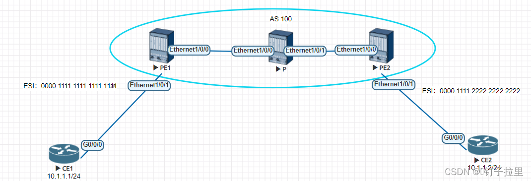
实验拓扑:
实验目的:
通过BGP EVPN 作为控制层面,MPLS LDP作为转发层面,实现2层跨广域网转发流量;
配置思路:
- 建立承载的广域网底层IGP协议;
- 配置MPLS LDP建立MPLS LSP隧道(构建数据层面);
- 配置物理接口ESI,创建EVPN实例并关联在BD中,子接口绑定BD。
- 配置广域网PE之间建立BGP EVPN(构建转发层面)
配置步骤:
一、建立承载的广域网底层IGP协议;
3台广域网设备创建OSPF进程并创建区域0,互联地址与环路口接口下宣告OSPF;
PE1:
ospf 1 router-id 1.1.1.1
 area 0.0.0.0

interface Ethernet1/0/0
 undo shutdown
 ip address 10.1.13.1 255.255.255.0
 ospf enable 1 area 0.0.0.0

 interface LoopBack0
 ip address 1.1.1.1 255.255.255.255
 ospf enable 1 area 0.0.0.0
P:
ospf 1 router-id 1.1.1.1
 area 0.0.0.0

 interface Ethernet1/0/0
 undo shutdown
 ip address 10.1.13.3 255.255.255.0
 ospf enable 1 area 0.0.0.0

 interface Ethernet1/0/1
 undo shutdown
 ip address 10.1.23.3 255.255.255.0
 ospf enable 1 area 0.0.0.0
PE2:
ospf 1 router-id 1.1.1.1
 area 0.0.0.0

interface Ethernet1/0/0
 undo shutdown
 ip address 10.1.13.1 255.255.255.0
 ospf enable 1 area 0.0.0.0

 interface LoopBack0
 ip address 1.1.1.1 255.255.255.255
 ospf enable 1 area 0.0.0.0
验证:
在P设备上查看OSPF邻居的建立情况,并在PE1测pingPE2的Loopback地址
P:
[P]dis ospf peer brief


          OSPF Process 1 with Router ID 3.3.3.3
                   Peer Statistic Information
Total number of peer(s): 2
 Peer(s) in full state: 2
-----------------------------------------------------------------------------
 Area Id         Interface                  Neighbor id          State
 0.0.0.0         Eth1/0/0                   1.1.1.1              Full
 0.0.0.0         Eth1/0/1                   2.2.2.2              Full
-----------------------------------------------------------------------------
PE1:
[PE1]ping -a 1.1.1.1 2.2.2.2
  PING 2.2.2.2: 56  data bytes, press CTRL_C to break
    Reply from 2.2.2.2: bytes=56 Sequence=1 ttl=254 time=25 ms
    Reply from 2.2.2.2: bytes=56 Sequence=2 ttl=254 time=2 ms
    Reply from 2.2.2.2: bytes=56 Sequence=3 ttl=254 time=2 ms
    Reply from 2.2.2.2: bytes=56 Sequence=4 ttl=254 time=2 ms
    Reply from 2.2.2.2: bytes=56 Sequence=5 ttl=254 time=2 ms

  --- 2.2.2.2 ping statistics ---
    5 packet(s) transmitted
    5 packet(s) received
    0.00% packet loss
    round-trip min/avg/max = 2/6/25 ms
二、配置MPLS LDP建立MPLS LSP隧道(构建数据层面);
全局配置mpls ldp,接口下使能mpls ldp
PE1:
mpls lsr-id 1.1.1.1
mpls
 mpls ldp

interface Ethernet1/0/0

 mpls
 mpls ldp
P1:
mpls lsr-id 3.3.3.3
mpls
 mpls ldp

interface Ethernet1/0/0

 mpls
 mpls ldp
 interface Ethernet1/0/1

 mpls
 mpls ldp
PE2:
mpls lsr-id 2.2.2.2
mpls
 mpls ldp

interface Ethernet1/0/0

 mpls
 mpls ldp
验证:
验证LSP隧道建立是否成功,并且验证标签可达性;
PE1:
[PE1]dis mpls lsp
Flag after Out IF: (I) - RLFA Iterated LSP, (I*) - Normal and RLFA Iterated LSP
Flag after LDP FRR: (L) - Logic FRR LSP
-------------------------------------------------------------------------------
                 LSP Information: LDP LSP
-------------------------------------------------------------------------------
FEC                In/Out Label    In/Out IF                      Vrf Name
1.1.1.1/32         3/NULL          -/-
2.2.2.2/32         NULL/48121      -/Eth1/0/0
2.2.2.2/32         48121/48121     -/Eth1/0/0
3.3.3.3/32         NULL/3          -/Eth1/0/0
3.3.3.3/32         48120/3         -/Eth1/0/0

//单向
[PE1]ping lsp ip 2.2.2.2 32
  LSP PING FEC: IPV4 PREFIX 2.2.2.2/32/ : 100  data bytes, press CTRL_C to break
    Reply from 2.2.2.2: bytes=100 Sequence=1 time=9 ms
    Reply from 2.2.2.2: bytes=100 Sequence=2 time=2 ms
    Reply from 2.2.2.2: bytes=100 Sequence=3 time=2 ms

  --- FEC: IPV4 PREFIX 2.2.2.2/32 ping statistics ---
    3 packet(s) transmitted
    3 packet(s) received
    0.00% packet loss
    round-trip min/avg/max = 2/4/9 ms
PE2:
[PE2]ping lsp ip 1.1.1.1 32
  LSP PING FEC: IPV4 PREFIX 1.1.1.1/32/ : 100  data bytes, press CTRL_C to break
    Reply from 1.1.1.1: bytes=100 Sequence=1 time=13 ms
    Reply from 1.1.1.1: bytes=100 Sequence=2 time=2 ms
    Reply from 1.1.1.1: bytes=100 Sequence=3 time=2 ms

  --- FEC: IPV4 PREFIX 1.1.1.1/32 ping statistics ---
    3 packet(s) transmitted
    3 packet(s) received
    0.00% packet loss
    round-trip min/avg/max = 2/5/13 ms
三、配置物理接口ESI,创建EVPN实例并关联在BD中,子接口绑定BD。
S系列的交换机和NE设备的EVPN实例配置如下(和CE系列的配置不一样)
PE1:
evpn vpn-instance Ender bd-mode
 route-distinguisher 10:10
 vpn-target 10:10 export-extcommunity
 vpn-target 10:10 import-extcommunity

 //在桥接域下调用EVPN实例
 bridge-domain 10
 evpn binding vpn-instance Ender

 //定义对接CE设备物理线路的ESI;
 interface Ethernet1/0/1

 esi 0000.1111.1111.1111.1111       //配置自定义的全网唯一10字节的ESI信息,通过物理接口为ESI,

 //在子接口下绑定BD;
 interface Ethernet1/0/1.10 mode l2
 encapsulation untag                    //对端为三层设备路由,发过来的数据包不携带tag,所以"允许不带标签的数据进入隧道"
 bridge-domain 10
PE2:
//创建EVPN实例名称为Ender,模式选择为bd-mode
evpn vpn-instance Ender bd-mode
 route-distinguisher 10:10
 vpn-target 10:10 export-extcommunity
 vpn-target 10:10 import-extcommunity

 //在桥接域下调用EVPN实例
 bridge-domain 10
 evpn binding vpn-instance Ender

 //定义对接CE设备物理线路的ESI;
 interface Ethernet1/0/1

 esi 0000.1111.2222.2222.2222       //配置自定义的全网唯一10字节的ESI信息,通过物理接口为ESI,

 //在子接口下绑定BD;
 interface Ethernet1/0/1.10 mode l2
 encapsulation untag                    //对端为三层设备路由,发过来的数据包不携带tag,所以"允许不带标签的数据进入隧道"
 bridge-domain 10
四、配置广域网PE之间建立BGP EVPN(构建转发层面)
通过PE之间建立BGP EVPN传递交互EVPN路由,通过EVPN2类路由携带的MAC地址实现同网段可达;
PE1:
bgp 100
 peer 2.2.2.2 as-number 100
 peer 2.2.2.2 connect-interface LoopBack0
 #
 ipv4-family unicast
  undo synchronization
  peer 2.2.2.2 enable
 #
 l2vpn-family evpn
  undo policy vpn-target
  peer 2.2.2.2 enable
PE2:
bgp 100
 peer 1.1.1.1 as-number 100
 peer 1.1.1.1 connect-interface LoopBack0
 #
 ipv4-family unicast
  undo synchronization
  peer 1.1.1.1 enable
 #
 l2vpn-family evpn
  undo policy vpn-target
  peer 1.1.1.1 enable
验证:
BGP EVPN邻居状态为Established,并且收到了5条前缀路由;
[PE2]dis bgp evpn peer

 BGP local router ID : 2.2.2.2
 Local AS number : 100
 Total number of peers : 1                 Peers in established state : 1

  Peer            V          AS  MsgRcvd  MsgSent  OutQ  Up/Down       State  PrefRcv
  1.1.1.1         4         100     1012     1015     0 14:36:49 Established        5
实验验证:
Ping测试验证:
CE1:
[CE1]ping -a 10.1.1.1 10.1.1.2
  PING 10.1.1.2: 56  data bytes, press CTRL_C to break
    Reply from 10.1.1.2: bytes=56 Sequence=1 ttl=255 time=2 ms
    Reply from 10.1.1.2: bytes=56 Sequence=2 ttl=255 time=3 ms
    Reply from 10.1.1.2: bytes=56 Sequence=3 ttl=255 time=2 ms

  --- 10.1.1.2 ping statistics ---
    3 packet(s) transmitted
    3 packet(s) received
    0.00% packet loss
    round-trip min/avg/max = 2/2/3 ms
EVPN路由验证:查看EVPN 一类二类三类的路由;
PE1:
[PE1]dis bgp evpn all routing-table


 Local AS number : 100

 BGP Local router ID is 1.1.1.1
 Status codes: * - valid, > - best, d - damped, x - best external, a - add path,
               h - history,  i - internal, s - suppressed, S - Stale
               Origin : i - IGP, e - EGP, ? - incomplete


 EVPN address family:              //A-D路由代表了类型1的路由,包含了通告了ESI标签
 Number of A-D Routes: 4
 Route Distinguisher: 10:10
       Network(ESI/EthTagId)                                  NextHop
 *>    0000.1111.1111.1111.1111:0                             127.0.0.1
 *>i   0000.1111.2222.2222.2222:0                             2.2.2.2
 Route Distinguisher: 1.1.1.1:0
       Network(ESI/EthTagId)                                  NextHop
 *>    0000.1111.1111.1111.1111:4294967295                    127.0.0.1
 Route Distinguisher: 2.2.2.2:0
       Network(ESI/EthTagId)                                  NextHop
 *>i   0000.1111.2222.2222.2222:4294967295                    2.2.2.2


 EVPN-Instance Ender:
 Number of A-D Routes: 3
       Network(ESI/EthTagId)                                  NextHop
 *>    0000.1111.1111.1111.1111:0                             127.0.0.1
 *>i   0000.1111.2222.2222.2222:0                             2.2.2.2
 *>i   0000.1111.2222.2222.2222:4294967295                    2.2.2.2

 EVPN address family:                //evpn地址簇下总的2类路由信息
 Number of Mac Routes: 2             //类型2的路由携带了mac信息,5000-0004-0000为CE1的接口MAC、5000-0005-0000为CE2的接口MAC、由2.2.2.2学习过来的
 Route Distinguisher: 10:10
       Network(EthTagId/MacAddrLen/MacAddr/IpAddrLen/IpAddr)  NextHop
 *>    0:48:5000-0004-0000:0:0.0.0.0                          0.0.0.0
 *>i   0:48:5000-0005-0000:0:0.0.0.0                          2.2.2.2


 EVPN-Instance Ender:               //EPVN实例Ender下的信息
 Number of Mac Routes: 2
       Network(EthTagId/MacAddrLen/MacAddr/IpAddrLen/IpAddr)  NextHop
 *>    0:48:5000-0004-0000:0:0.0.0.0                          0.0.0.0
 *>i   0:48:5000-0005-0000:0:0.0.0.0                          2.2.2.2

 EVPN address family:
 Number of Inclusive Multicast Routes: 2
 Route Distinguisher: 10:10
       Network(EthTagId/IpAddrLen/OriginalIp)                 NextHop
 *>    0:32:1.1.1.1                                           127.0.0.1
 *>i   0:32:2.2.2.2                                           2.2.2.2


 EVPN-Instance Ender:                //类型三的路由经典的通告了更新源地址
 Number of Inclusive Multicast Routes: 2
       Network(EthTagId/IpAddrLen/OriginalIp)                 NextHop
 *>    0:32:1.1.1.1                                           127.0.0.1
 *>i   0:32:2.2.2.2                                           2.2.2.2

 EVPN address family:
 Number of ES Routes: 2
 Route Distinguisher: 1.1.1.1:0
       Network(ESI)                                           NextHop
 *>    0000.1111.1111.1111.1111                               127.0.0.1
 Route Distinguisher: 2.2.2.2:0
       Network(ESI)                                           NextHop
 *>i   0000.1111.2222.2222.2222                               2.2.2.2


 EVPN-Instance Ender:
 Number of ES Routes: 1
       Network(ESI)                                           NextHop
 *>    0000.1111.1111.1111.1111                               127.0.0.1


 451
451

 被折叠的 条评论
为什么被折叠?
被折叠的 条评论
为什么被折叠?
 到【灌水乐园】发言


