


数字调制技术之正交调制
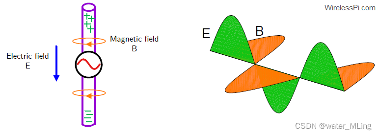
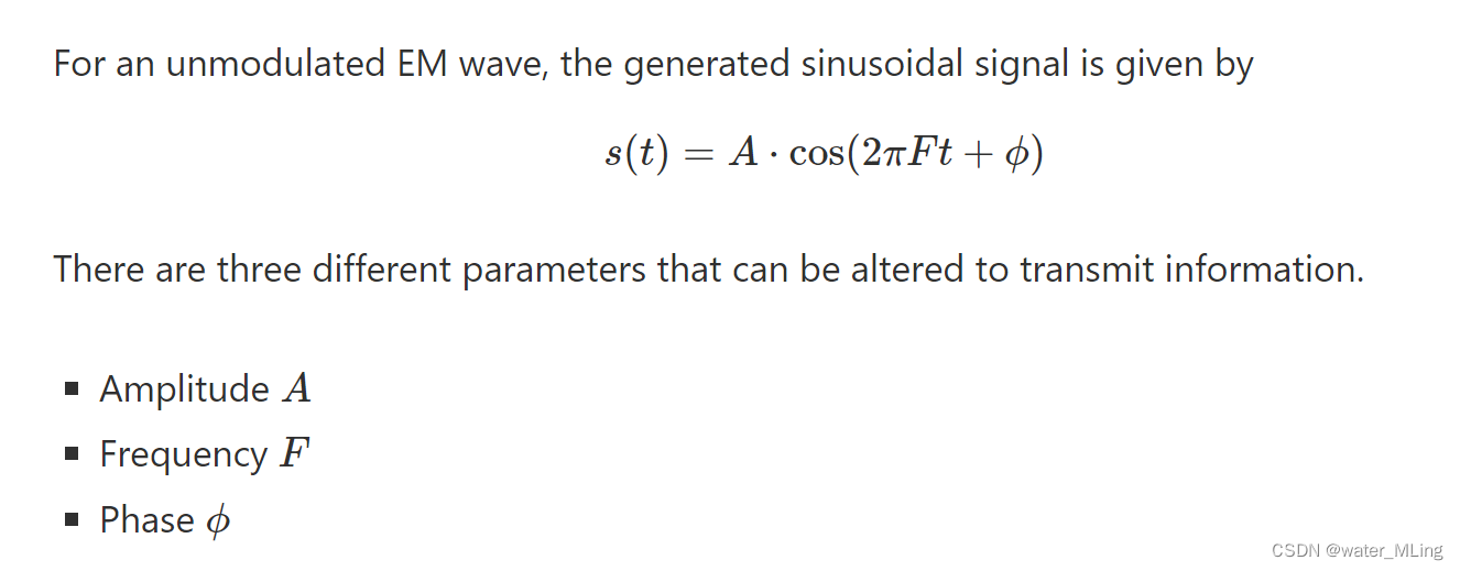
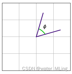
- 正弦波的表示
- 键控调制解调原理(ASK、FSK、PSK)
- 高阶调制原理
- IQ调制原理(MASK、MFSK、MPSK)
一、. An Electromagnetic Wave
二、 键控调制解调原理(ASK、FSK、PSK)
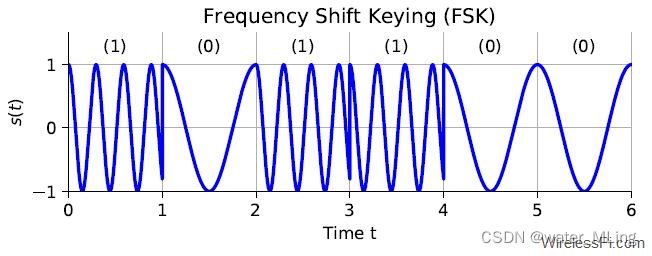
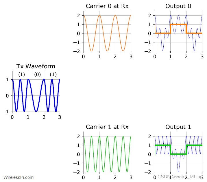
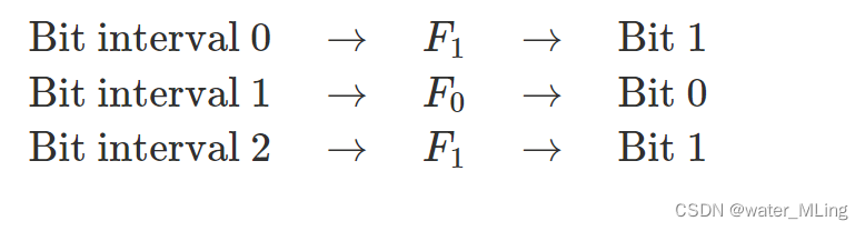
- Frequency Shift Keying (FSK)
_FSK modualtion
_FSK Demodulation
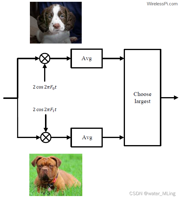
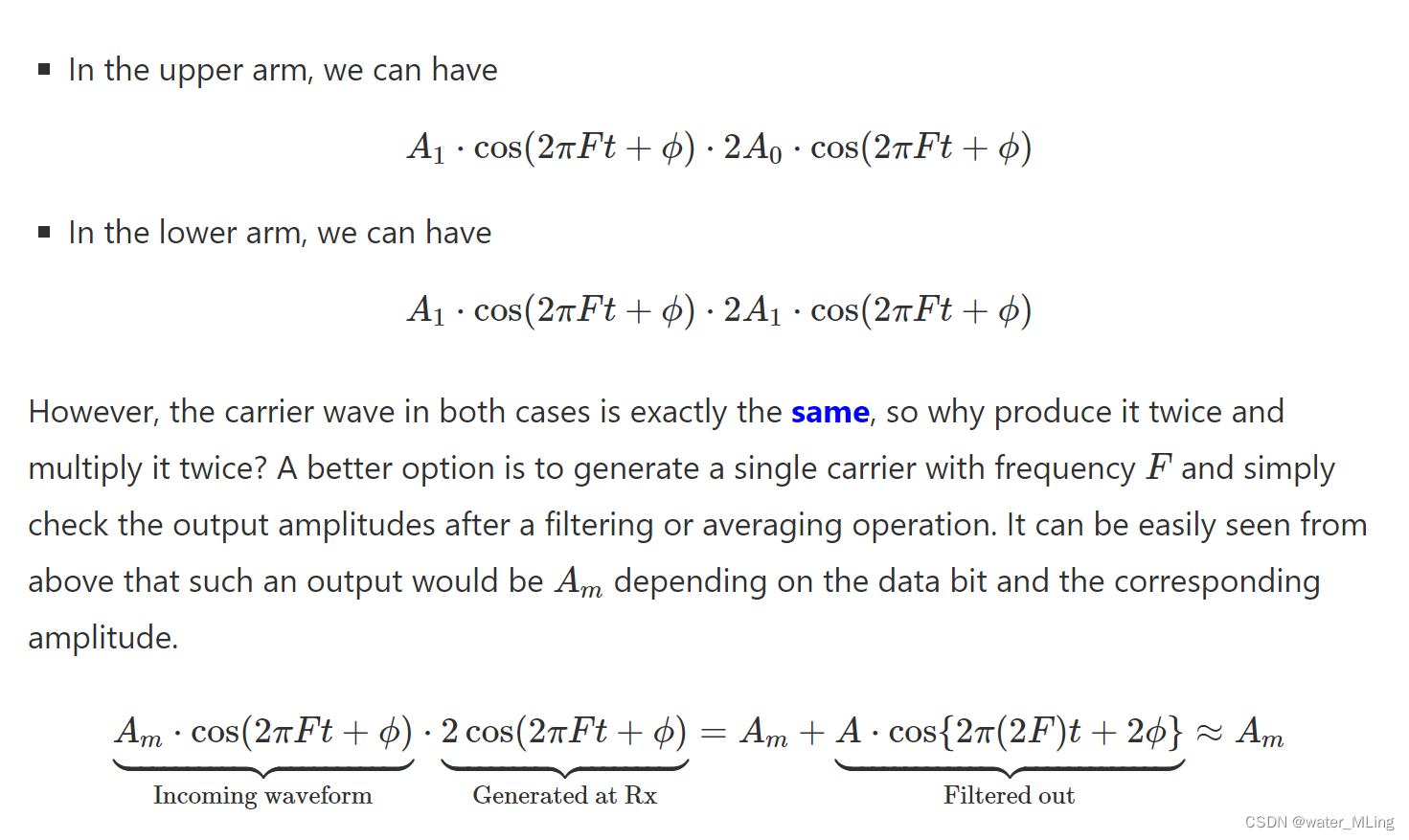
In the upper arm, the product of cross-terms is a sum of two cosine waves, one at the difference frequency while the other at the sum frequency.
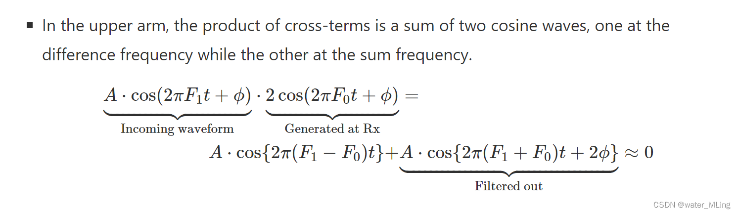
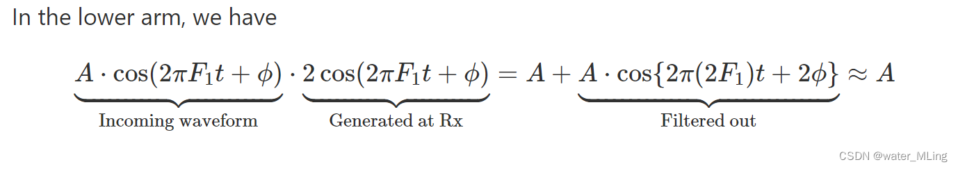
After the averaging or filtering operation, only the DC term A remains (under ideal conditions).
2.Amplitude Shift Keying (ASK)
_ASK Modulation
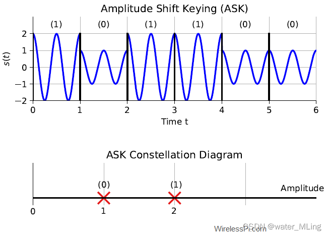
_ASK Demodulation

三、.Higher-Order Modulations
Digital electronics are constrained to work on only two levels by electronic switches which in the simplest case are either on or off. Actual digital communication systems require quite complicated signal processing workload both at the Tx and Rx ends that can be performed only by a device more intelligent than an electronic switch, such as an Application Specific Integrated Circuit (ASIC), Field Programmable Gate Array (FPGA), Digital Signal Processor (DSP) or a General Purpose Processor (GPP).(硬件技术的发展,可以表示的符号数表多了,所以可以在物理上实现IQ调制)
In the case of 4-FSK for instance, this implies that four different carrier frequencies can be utilized where each of them represents a set of two bits.
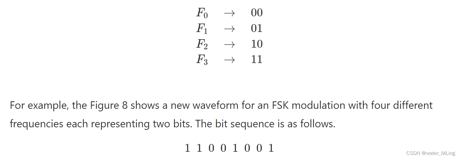
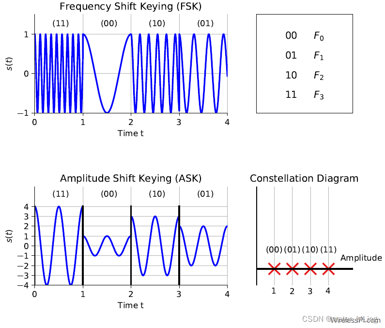
In conclusion, a higher granularity of more than two modulation levels are required for higher-rate schemes.
四、IQ调制原理(MASK、MFSK、MPSK)
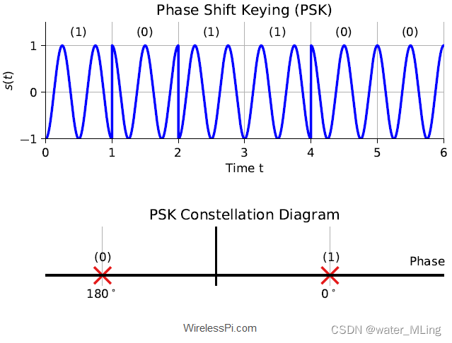
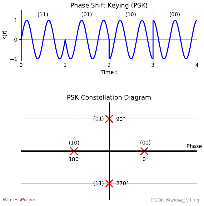
1.Phase Shift Keying (PSK)
Phase Shift Keying (PSK), the data is transmitted by changing the phase of a constant frequency carrier wave at each signaling interval.
_PSK Modulation
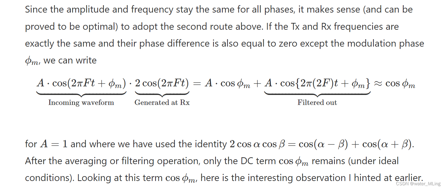
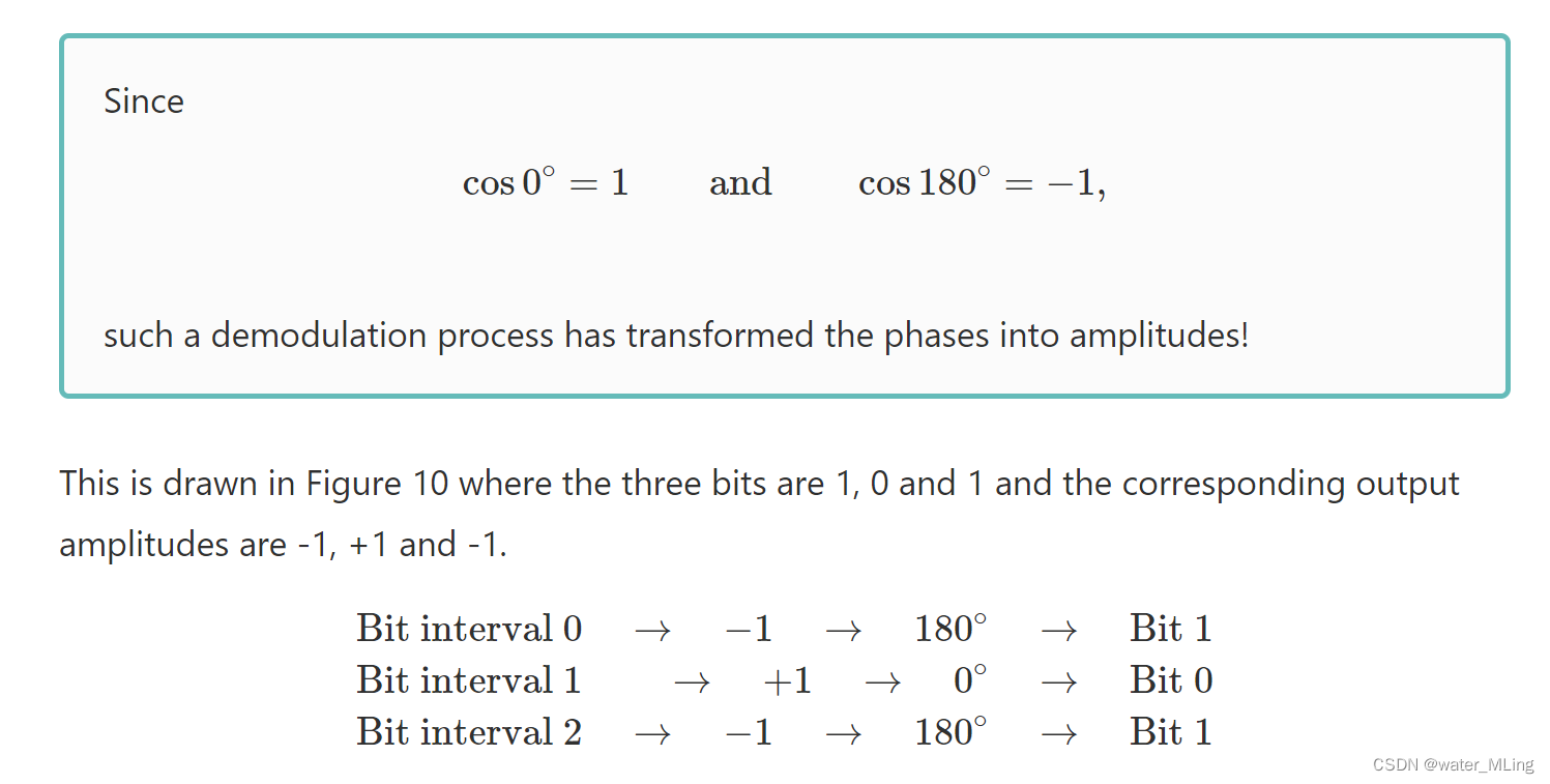
_PSK Demodulation
a PSK system requires a 2-dimensional constellation diagram. And that has made all the difference, as we shortly see.
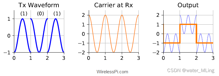
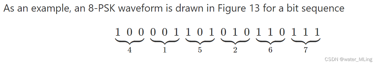
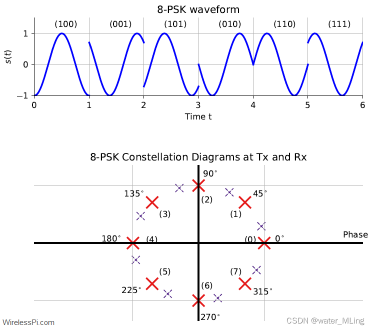
- PSK Example
- 8-PSK with a Phase Offset
Demodulation with Cosine
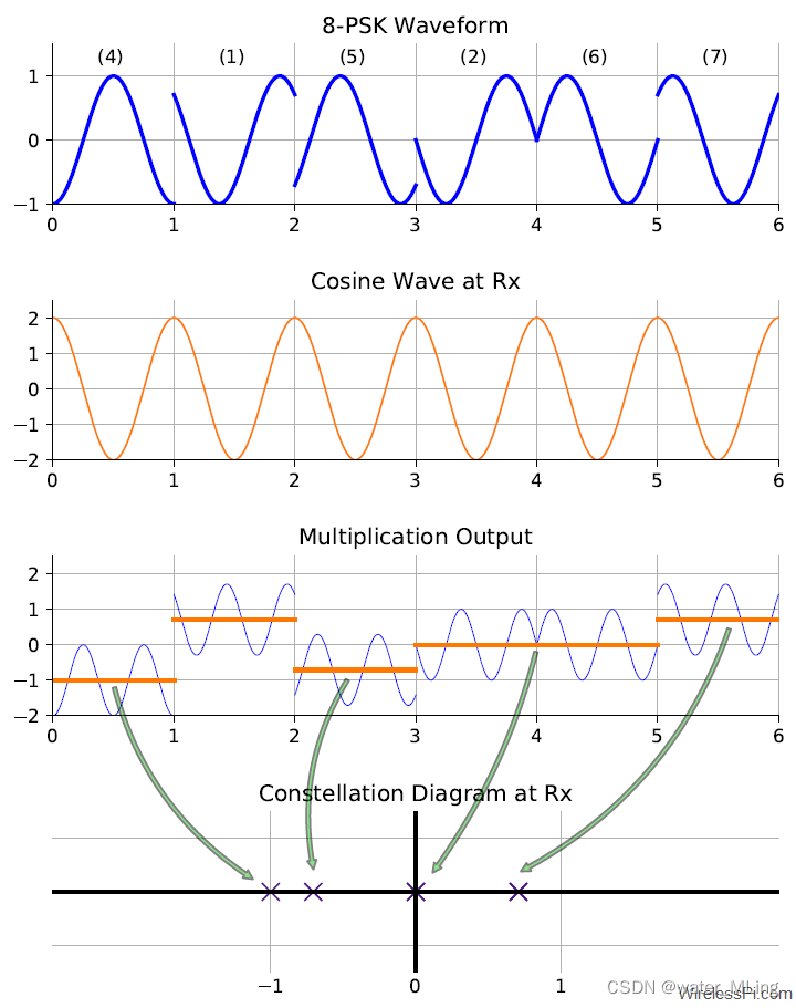
Figure 14: Demodulation process of an 8-PSK waveform with a cosine wave
Demodulation withSine
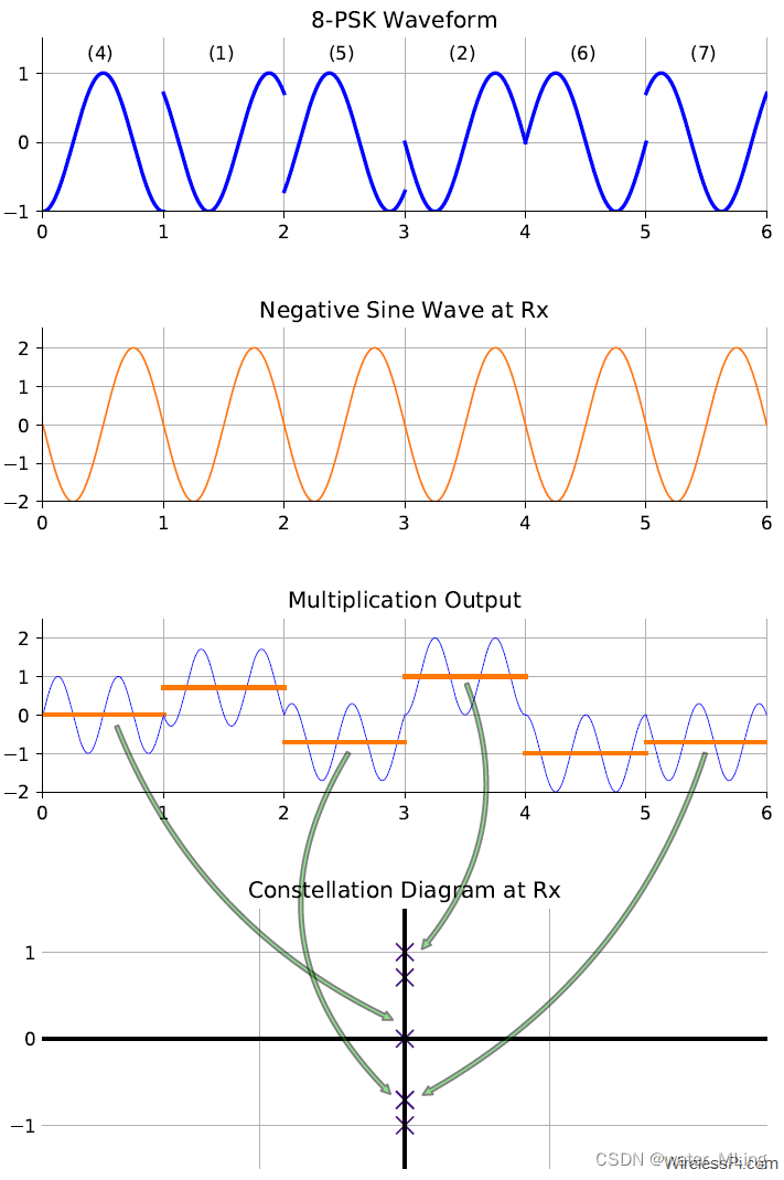
Figure 15: Demodulation process of an 8-PSK waveform with a negative sine wave
2.the implementation of Quadrature Amplitude Modulation (QAM).
We have learned that PSK modulation chooses discrete phases on the same circle. Moreover, I/Q refers to points on a 2-D plane and hence I/Q data involves both amplitude and phase of the carrier. So why do modulation points necessarily have to be on the same circle? They don’t have to. Since discrete amplitudes can be chosen in ASK modulation, we can combine one amplitude and one phase at each signaling interval. Such a strategy gives rise to the most widely used digital modulation technique known as Quadrature Amplitude Modulation (QAM). Let us discuss this concept through a QAM modulator and demodulator that form the backbone of your WiFi, cellular and other high rate communication systems.
- Modulator
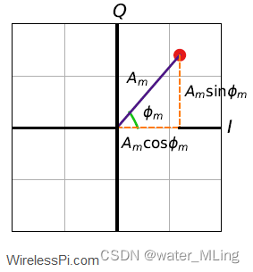
Figure 16: I/Q plane and modulation parameters
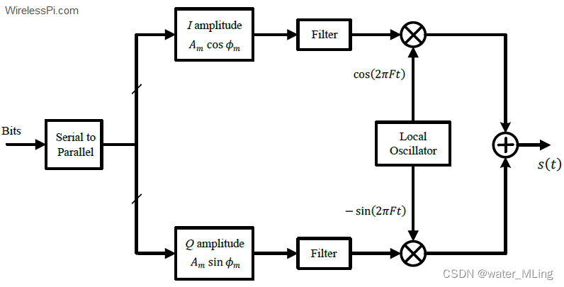
Figure 17: A block diagram for a QAM modulator
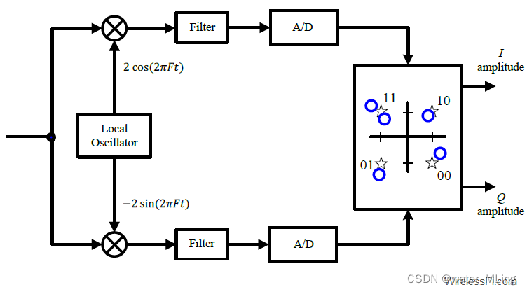
Figure 18: A block diagram for a QAM demodulator
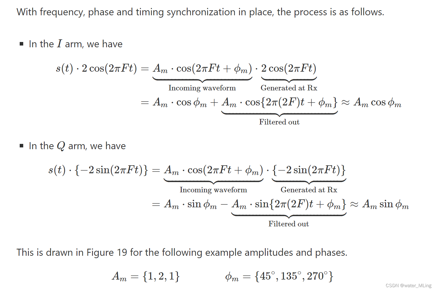
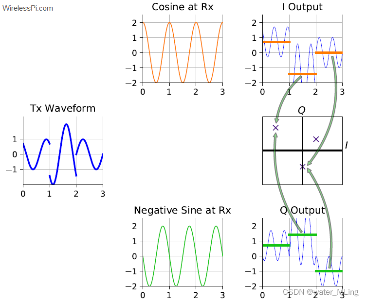
I/Q demodulation process and projections on I and Q axes


 2722
2722

 被折叠的 条评论
为什么被折叠?
被折叠的 条评论
为什么被折叠?
 到【灌水乐园】发言


