


WiFi MAC Randomization
Before we learn about this feature , lets see how the MAC address look like. Most of us know about it, So I am just showing the same in the below figure.
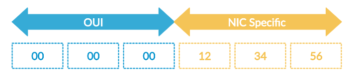
Figure 1 : MAC Address Format
MAC address consists total 6 bytes. First 3 bytes are organization OUI and it identifies the manufacturer of the device , and next 3 bytes uniquely identifies the device and it is NIC Specific.
Now we will learn about this feature and we will see the sniffer captures for different MAC Randomization settings.
Before we learn about the WiFi MAC Randomization, we will first check the locally administered MAC Addresses range that devices will be generating as a random MAC Addresses. If any device is generating the random MAC Address then it should set the locally administered bit.
Locally Administered MAC Addresses
There are 4 ranges of Locally Administered Address Ranges that can be used
x2-xx-xx-xx-xx-xx
x6-xx-xx-xx-xx-xx
xA-xx-xx-xx-xx-xx
xE-xx-xx-xx-xx-xx
Where x can be any hex value
I have used wpa_supplicant to test the scenarios and the post refers to Random MAC implementation in WPA supplicant.
MAC Randomization is a technique that protects WiFi enabled devices being tracked. If this feature is enabled , the device will not be shown its reals MAC in the air. All the MAC layer operations will happen with the random MAC.
Some places, for example shopping malls, stores, or other public areas, might use the unique MAC address to track the visitor movement in that area. Frequently changing the a device’s MAC address will have a negative impact on the location tracking and for the data analytics.
Few devices will generate the different random MAC every time based on the random MAC life time in the scanning phase, and they will generate the different MAC every time while connecting to the AP. And few devices will generate the same random MAC every time they connect the same SSID.
There will be multiple settings that will be enabled with the MAC Randomization. And the implementation is dependent on the vendors. But the idea will be not to show up the real mac.
There are two different ways that MAC Randomization happen.
- MAC Randomization at Scanning Phase
- MAC Randomization at Association Phase.
- MAC Randomization at Scanning+Association
MAC Randomization at Scanning Phase
In the Passive Scanning there are multiple ways that Vendors implement the MAC Randomization.
- Maintain Real MAC for Scanning
- Maintain Random MAC for Scanning [Locally Administered MAC Address]
- Maintain Random MAC for scanning, but still maintain the same OUI [But locally Administered]
1. Maintain Real MAC for Scanning
There is nothing new with this one, because the same real MAC will be used for scanning.
2. Maintain Random MAC for Scanning [Locally Administered MAC]
Here based on the life time of a random MAC, the scanning will happen based on the generated MAC. Once the life time of a Random MAC is expired the new Random MAC will be generated. The new Random MAC should be from the locally administered address space.
Default Random MAC life time
60 Seconds is the Default Random MAC life time. It can be changed based on the vendor requirement. In the sniffer captures time may vary because the probes may not be sent exactly at 60 seconds. Still you will see the changed MAC address.
Observe the below sniffer capture for this scenario. You have to properly capture the required probes, you can easily identify the frames in the RF Chamber. If you are doing it in a open air then you should properly note the Interface address that is getting changed by using ifconfig , and then properly analyze the air packets.
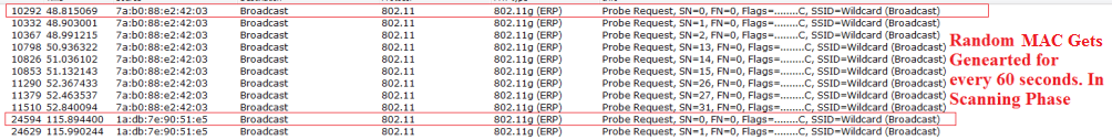
Figure 2 : Random MAC gets generated for every 60 seconds
3. Maintain Random MAC for scanning, but still maintain the same OUI [Locally Administered MAC]
This is also similar to the above one, but the only difference is that we will still maintain the same OUI, but the NIC address will be changed. Observe the below capture to check this scenario. I have filtered only the required frames. Here the real OUI of my device is “e8:de:27”. But in the sniffer you can observe that OUI is taken from the locally administered address space.
The random MAC that wpa_supplicant generated is “ea:de:27”.
Real MAC of the device is “e8:de:27:a9:94:fb“.
When we are going to maintain the OUI, then the supplicant will only chanage the 1st octet of OUI to locally administered MAC Address.
So the generated Random MAC is “ea:de:27:66:8f:ed”

Figure 3 : Random MAC for every 60 seconds in scanning phase , but Still Maintain the same OUI
Till now we have seen about the MAC Randomization in the Discovery Phase , now we will check the MAC randomization in the Association.
MAC Randomization at Association Phase
At the time of Association there are multiple ways that Vendors implement the MAC Randomization.
My Device Real WiFi MAC Address is given below for reference
e8:de:27:a9:94:fb
- Maintain Real MAC for Association
- Maintain Random MAC for Association [Locally Administered MAC Address]
- Maintain Random MAC for Association, but still maintain the same OUI [Locally Administered MAC Address]
1. Maintain Real MAC for Association
There is nothing new with this one, because the same real MAC will be used for scanning. This was the implementation that used to be.
2. Maintain Random MAC for Association [Locally Administered MAC]
Here the vendor uses the Random MAC for Association instead of the Real MAC.
Observe the below capture and check that the Random MAC is used for Association. Observe that the MAC Address is within the range of locally administered mac address space.
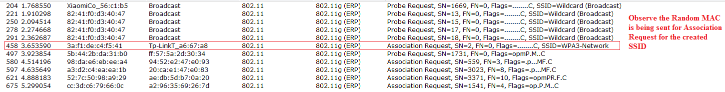
Figure 4 : Observe Random MAC for Association Request
3. Maintain Random MAC for Association, but still maintain the same OUI [Locally Administered MAC]
Here the Association happens using the random MAC , but the OUI will be still maintained, but the 1st octet should be locally administered.
Here the MAC Address of my device is “e8:de:27:a9:94:fb”. Generated Random MAC Address is ea:de:27:a9:94:fb [ 1st Octet is locally administered]

Figure 5 : Observe the Random MAC, but still the OUI is maintained
Till now we have seen the Discovery phase and Association phase differently. Now we will see them together.
MAC Randomization at Scanning+Association
Below are the different implementation scenarios. And it will be based on how the vendor implements it.
There are multiple combinations that can be implemented for the MAC Address randomization. Below are the scenarios that can be implemented. And it all depends on the vendor to select the any method that he wants.
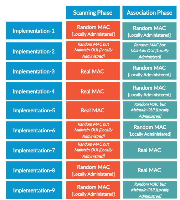
Figure 6 : Random MAC implementation scenarios
If we combine Random MAC Maintaining the OUI with Random MAC, then the above table will be summarized as below.
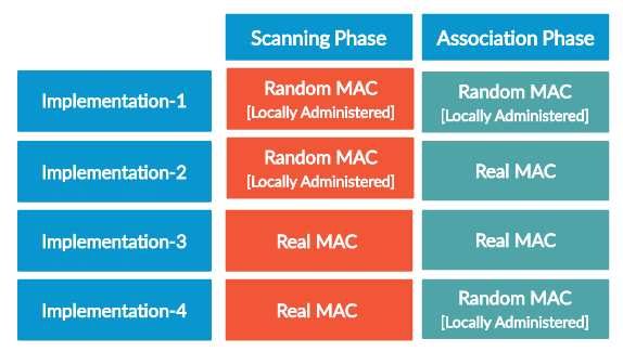
Figure 7 : Random MAC Summarization table
Few Vendors implement different MAC every time they associate to the AP. Few Vendors always use the same Random MAC every time they associate to the same SSID.
And in the scanning phase, vendors can make use of the Random MAC Address life time , so that the Scanning happens with the particular MAC based on the life time of a MAC, and then it changes to some other MAC for every X seconds.
Now lets see the sniffer captures for the scenarios that are shown in the Figure 7.
Implementation 1
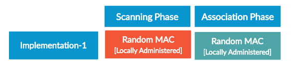
Figure 8 : Scenario 1
In this scenario, Scanning will happen with Random, Association also happens with Random MAC.
If you have to check this scenario, you should properly note down the MAC Address of the device at the time of scanning and note down the MAC Address of the device at the time of Association.
In the clear air environment you will be able to get the sniffer capture properly, in the open air you have to properly note down the mac address and filter in the wireshark properly. Observe the capture below for this scenario. Observe that random mac at the scanning phase is based on the locally administered address pool, and the random mac at the association is also locally administered random MAC.
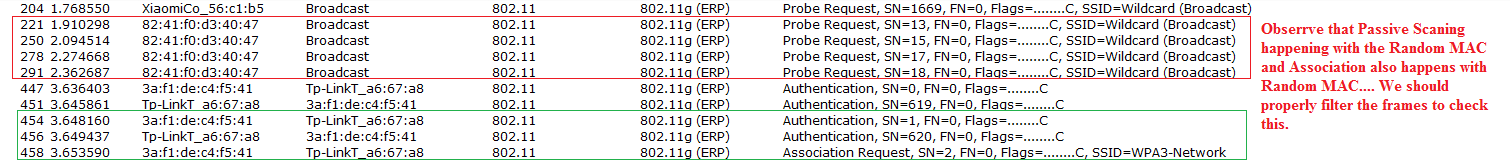
Figure 9 : Scenario 1 Sniffer Capture
Implementation 2
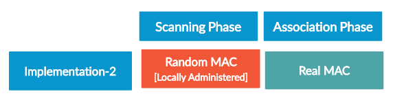
Figure 10 : Scenario 2
In this scenario, Scanning will happen with Random MAC, Association happens with Real MAC.
If we have to check this scenario , we should note down the Device MAC Address at the time of the scanning and note down the device MAC Address at the time of Association. After that filter the wireshark capture to check the behavior.
Observe the below sniffer capture to check the behavior. Huawei device is scanning with the real MAC based on the locally administered random mac range, but the association is happening with the real MAC.
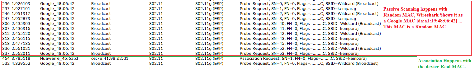
Figure 11: Scenario 2 Sniffer Capture
Implementation 3
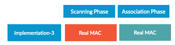
Figure 12 : Scenario 3
There is nothing new with the scenario. We always see the real MAC at the time of scanning and Association. It is normal scenario that we used to see before.
Implementation 4

Figure 13 : Scenario 4
In this scenario Scanning happens with the real MAC and Association happens with the Random MAC [Locally administered]. We should properly check the changing MAC addresses and filter the captured sniffer capture to check this.

Figure 14 : Scenario 4 Sniffer Capture
Connecting a MAC to the AP Which does n’t maintain OUI any OUI, and not Locally Administered
Now lets connect a client with random MAC by not maintaining the locally administered address space. And the following is the MAC Address that I have used. Here I have still observed that the client is able to connect to the AP.
Random MAC Used which does not maintain OUI, and not locally administered : 1c:e4:56:34:de:de.
Here the above MAC is also able to connect to the AP without any issues.
Observe the below successful 4-way handshake below in the capture for this MAC.Random MAC which doesn’t have OUI, And which does not maintain locally administrated MAC
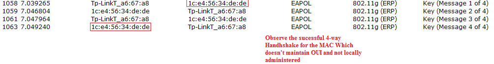
Figure 15 : Succesful handshake for the MAC Which doesn’t maintain OUI , and not locally administered
This is all about the WiFi MAC Randomization , and the implementation depends on the vendors. They can implement any of the above scenarios based on the implementation needs and demands.
Still few devices will use the Real MAC for sending the ANQP queries in HS2.0. The real identity of those devices can be easily known if stations use their real MAC address for querying the AP. So, the real MAC address of a client can still be identified by using Hotspot 2.0 Honeypot. So, implementing the random MAC For ANQP requests are also vendor dependent.
ANQP (Access Network Query Protocol)
ANQP, or Access Network Query Protocol, is a communication protocol used in wireless networks to query information about available networks and their capabilities. It was developed by the Wi-Fi Alliance and is standardized under IEEE 802.11u.
The main purpose of ANQP is to enable wireless clients to obtain information about the available Wi-Fi networks before connecting to them. This information can include network configuration details, such as the supported authentication and encryption methods, as well as other network parameters such as location information, services offered, and quality of service (QoS) capabilities.
ANQP enables wireless clients to make informed decisions about which networks to connect to based on the available information. This can improve the user experience by ensuring that clients connect to networks that meet their requirements and expectations.
ANQP operates at the link layer of the OSI model and is used to exchange information between the wireless client and the access point (AP). The ANQP protocol uses the User Datagram Protocol (UDP) for transmission and typically operates over port 8909.
ANQP Messages
ANQP messages are used to exchange information between the wireless client and the AP. There are three types of ANQP messages:
- Request messages: These messages are sent by the wireless client to request information from the AP. A request message includes a list of information elements that the client is interested in.
- Response messages: These messages are sent by the AP in response to a request message. A response message includes the requested information elements.
- Notification messages: These messages are sent by the AP to notify the client of changes to the available networks or their capabilities.
ANQP Information Elements
ANQP messages include information elements that provide details about the available networks and their capabilities. These elements are organized into categories that include:
- Capability Information: This category includes information elements that describe the capabilities of the AP and the network, such as the supported authentication and encryption methods.
- Network Authentication Type: This category includes information elements that describe the authentication methods used by the network.
- Operating Class: This category includes information elements that describe the frequency band and channel number used by the network.
- Roaming Consortium: This category includes information elements that describe the roaming agreements between networks.
- Emergency Services: This category includes information elements that describe the emergency services available on the network.
- Venue Name: This category includes information elements that describe the name and location of the venue where the network is located.
- Geographic Location: This category includes information elements that describe the geographic location of the network.
- Hotspot 2.0: This category includes information elements that describe the Hotspot 2.0 service and the available service providers.
ANQP Operation
ANQP operates in a client-server model. The wireless client sends a request message to the AP, which responds with a response message that includes the requested information elements. If the client is interested in additional information, it can send another request message.
ANQP also supports notifications, which enable the AP to send updates to the client about changes to the available networks or their capabilities. This can include information about newly available networks, changes to network parameters, or changes to the QoS capabilities of a network.
ANQP also supports caching of information elements, which can improve the performance of the protocol by reducing the number of request messages that need to be sent. When an AP receives a request message, it can check its cache to see if it has the requested information elements. If the elements are in the cache, the AP can send a response message immediately without needing to retrieve the information again.
ANQP Applications
ANQP is used in a variety of applications that include:
- Wi-Fi offloading: ANQP can be used to provide information about available Wi-Fi networks to mobile devices, enabling them to offload data traffic from cellular networks to Wi-Fi networks when they are in range. This can help to reduce the load on cellular networks and improve the user experience by providing faster and more reliable data connectivity.
- Venue Wi-Fi: ANQP can be used in venues such as airports, stadiums, and shopping malls to provide information about the available Wi-Fi networks and their capabilities. This can enable visitors to connect to the most appropriate network based on their needs and improve their experience while at the venue.
- Hotspot 2.0: ANQP is used in the Hotspot 2.0 service to provide information about the available service providers and their capabilities. This can enable users to connect to trusted Wi-Fi networks automatically, without the need for manual configuration.
- Public safety: ANQP can be used to provide information about the emergency services available on Wi-Fi networks. This can be particularly useful in public safety applications, where it is important to quickly and reliably connect to emergency services in the event of an emergency.
Conclusion
ANQP is an important protocol for wireless networks that enables clients to obtain information about available networks and their capabilities before connecting to them. It provides a standardized mechanism for exchanging information between clients and access points and supports a wide range of information elements that can be used to describe the network and its services. ANQP is used in a variety of applications, including Wi-Fi offloading, venue Wi-Fi, Hotspot 2.0, and public safety, and is an important tool for improving the user experience and enhancing the functionality of wireless networks.
Access Network Query Protocol
ANQP is an Advertisement Protocol implemented using the GAS frames allowing any STA to query another STA about ANQP elements even before the association event.
ANQP Information Element
ANQP Information Elements are additional data that can be sent from the AP to any STA (including other APs) to provide identify of the APs network and service provider. The STA can query for which ANQP elements are available for being query using the Query List element within a query, in which case the AP will reply with the Capability List elements indicating what other ANQP elements can be queried. Here are the ANQP elements that can be returned in the capabilities List element
- Venue Name: the this information element defines the venue group and venue type.
- Domain Name: this information element specifies the APs domain name.
- Network Authentication Type: if the network has ASRA, this information element defines the authentication type being used by the hotspot network.
- Roaming Consortium List: this information element contains information identifying the network and service provider, whose security credentials can be used to authenticate with the AP transmitting this element.
- IP Address Availability: this information element provides clients with information about the availability of IP address versions and types which could be allocated to those clients after they associate to the hotspot AP.
- NAI Realm: this information element identifies and describes a NAI realm accessible using the AP and the method that this NAI realm uses for authentication.
- 3GPP Cellular Network Data: this information element defines information for a 3GPP Cellular Network for hotspots that have roaming relationships with cellular operators.
- Connection Capability: this information element defines hotspot protocol and port capabilities to be sent in an ANQP information element.
- Operating Class: this information element defines the channels on which the hotspot is capable of operating.
- Operator Friendly Name: this information element allows the definition of a free-form text field that can identify the operator and additional information about the location.
- WAN Metrics: this information element provides hotspot clients information about access network characteristics such as link status, capacity and speed of the WAN link to the Internet.


 5618
5618

 被折叠的 条评论
为什么被折叠?
被折叠的 条评论
为什么被折叠?
 到【灌水乐园】发言


