


文章目录
安卓的graphics提供了2D图形各种绘制工具,如Canvas(画布), color filters(颜色过滤器), points(点), rectangles(矩形)等,利用这些工具可以直接在界面上进行绘制。
本文主要讲的是自定义View时我们经常用到的Canvas和Paint,像平时画画一样,我们需要画布和画笔,而Canvas就是画布,Paint就是画笔.
Canvas官网地址:
https://developer.android.com/reference/android/graphics/Canvas.html
Paint官网地址:
https://developer.android.com/reference/android/graphics/Paint.html
Paint常用方法一览
Paint.setAntiAlias(boolean flag);//设置抗锯齿效果 设置true的话边缘会将锯齿模糊化
Paint.setDither(boolean flag);//设置防抖动,设置true的话图片看上去会更柔和点
Paint.setColor(int color);//设置画笔颜色
###TODO
Paint.setARGB(int a, int r, int g, int b); //设置画笔的ARGB值
Paint.setAlpha(int alpha);//设置画笔的Alpha值
Paint.setStyle(); //设置画笔的style (三种:FILL填充 FILL_AND_STROKE填充加描边 STROKE描边 )
Paint.setStrokeWidth(float width);//设置描边宽度

Paint.setXfermode(Xfermode xfermode);//设置图形重叠时的处理方式,如合并,取交集或并集,经常用来制作橡皮的擦除效果
Paint.setShader(Shader shader);//设置图像效果,使用Shader可以绘制出各种渐变效果
Paint.setShadowLayer(float radius ,float dx,float dy,int color);//在图形下面设置阴影层,产生阴影效果,radius为阴影的半径,dx和dy为阴影在x轴和y轴上的距离,color为阴影的颜色
//下面写文本的时候经常用到的
Paint.setTextSize(float textSize);//设置画笔文字大小
Paint.measureText(String text);//测试文本的长度
Paint.setTextAlign(Paint.Align align);// CENTER(文本居中) LEFT(文本左对齐) RIGHT(文本右对齐)
先来看上面Paint的几个主要方法,结合代码和效果图:
  Paint.Style.FILL //填充
  Paint.Style.FILL_AND_STROKE //填充加描边
  Paint.Style.STROKE //描边
测试伪代码:
Paint mPaint= new Paint();
 mPaint.setColor(Color.RED);//画笔颜色为红色
 mPaint.setStrokeWidth(80); //描边宽度为80(为了区分效果,特意设置特别大)

 float radius = 100f;
// 填充
mPaint.setStyle(Paint.Style.FILL);
canvas.drawCircle(400, 500, radius, mPaint);
// 描边
mPaint.setStyle(Paint.Style.STROKE);
canvas.drawCircle(400, 200, radius, mPaint);
// 描边加填充
mPaint.setStyle(Paint.Style.FILL_AND_STROKE);
canvas.drawCircle(400, 900, radius, mPaint);
来看效果图:
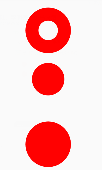
如图,根据测试,设置FILL_AND_STROKE模式时在其圆的外围的描边宽度并不是StrokeWidth的宽度,而是StrokeWidth/2的宽度.
Shader是着色器,用来给图像着色,Shader 是基类基类,它有5个已知的子类:
BitmapShader,
ComposeShader,
LinearGradient,
RadialGradient,
SweepGradient
在讲这5个子类之前,先了解一个枚举Shader.TileMode,它里面有三个值:{CLAMP,REPEAT,MIRROR}:
- Shader.TileMode.CLAMP:
如果shader绘制范围大于原有的范围时,会用原有图像四边的颜色填充剩余空间。 - Shader.TileMode.REPEAT:
在水平和竖直方向重复shader图像。 - Shader.TileMode.MIRROR:
在水平和竖直方向重复shader图像,这一点和REPEAT相似,不同的是MIRROR模式下相邻的两个图像互为镜像。
接下来结合例子分别来看一下Shader的5个子类和Shader.TileMode的使用姿势。
先来看下原图(用我家两只猫咪镇楼!)

BitmapShader
BitmapShader本质上就是绘制一个bitmap,并用这个bitmap对需要绘制的图形进行填充。
BitmapShader(Bitmap bitmap, Shader.TileMode tileX, Shader.TileMode tileY)
BitmapShader初始化时的三个参数:
| BitmapShader参数 | 备注 |
|---|---|
| bitmap | 用来填充图形的Bitmap |
| tileX | X轴Bitmap用Shader.TileMode模式填充 |
| tileY | Y轴Bitmap用Shader.TileMode模式填充 |
示例:
BitmapShader shader = new BitmapShader(bitmap, BitmapShader.TileMode.CLAMP, BitmapShader.TileMode.MIRROR);
mPaint.setShader(shader);
canvas.drawRect(0, 0, getMeasuredWidth(), getMeasuredHeight(), mPaint);
效果图:
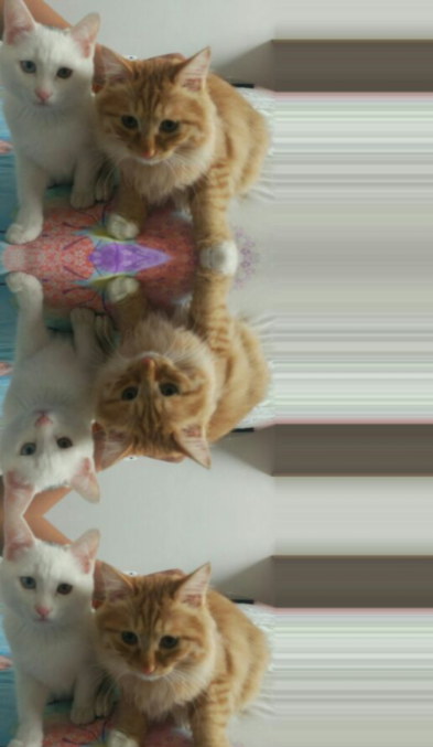
X轴用TileMode.CLAMP模式,即用bitmap的右边缘去填充X轴其余空间,
Y轴用TileMode.MIRROR模式,即在用相邻两张图像互为镜像的方式填充整个Y轴其余空间。
X轴和Y轴分别换一下参数模式:
BitmapShader shader = new BitmapShader(bitmap, BitmapShader.TileMode.MIRROR, BitmapShader.TileMode.REPEAT);
mPaint.setShader(shader);
canvas.drawRect(0, 0, getMeasuredWidth(), getMeasuredHeight(), mPaint);
效果图:

X轴用TileMode.MIRROR模式,即用相邻两张图像互为镜像的方式填充整个X轴其余空间,
Y轴用TileMode.REPEAT模式,即用相同的图像重复填充整个Y轴其余空间。
LinearGradient
LinearGradient(float x0, float y0, float x1, float y1, int color0, int color1,TileMode tile)
LinearGradient是沿一条直线用来创建线性渐变效果,(x0,y0),(x1,y1)分别是起始坐标和终止坐标,color0,color1分别是起始颜色和终止颜色,tile为
Shader.TileMode(CLAMP,REPEAT,MIRROR)模式中的一个。
| LinearGradient参数 | 备注 |
|---|---|
| x0 | 渐变线起始坐标的X坐标 |
| y0 | 渐变线起始坐标的Y坐标 |
| x1 | 渐变线终止坐标的X坐标 |
| y1 | 渐变线终止坐标的Y坐标 |
| color0 | 渐变线起始颜色 |
| color1 | 渐变线终止颜色 |
| tile | 渐变线用Shader.TileMode模式填充 |
示例:
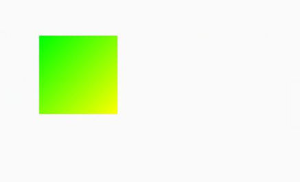
LinearGradient linearGradient = new LinearGradient(200, 200, 600, 600, Color.GREEN, Color.YELLOW, Shader.TileMode.MIRROR);
mPaint.setShader(linearGradient);
canvas.drawRect(200, 200, 600, 600, mPaint);
效果图:
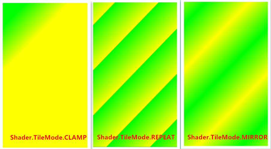
下面修改一下代码,扩大一下绘制范围:
canvas.drawRect(0, 0, getMeasuredWidth(), getMeasuredHeight(), mPaint);
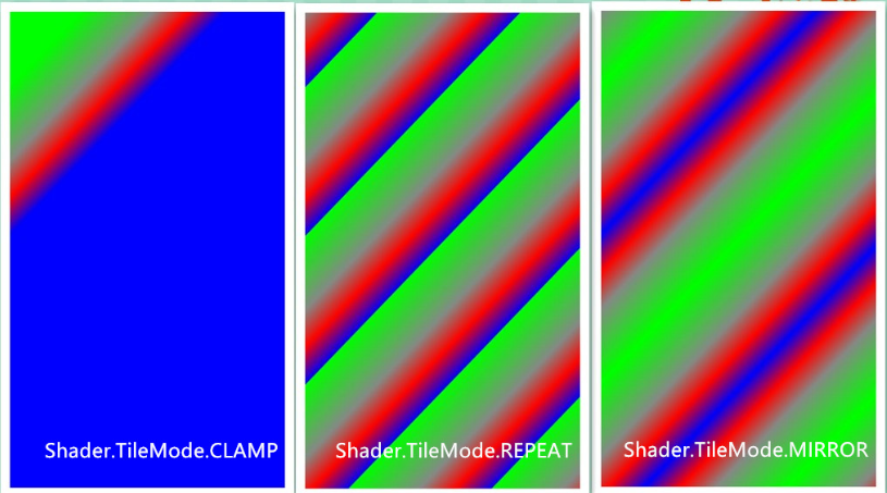
并且分别在LinearGradient构造函数中设置Shader.TileMode为CLAMP,REPEAT,MIRROR:
效果图:
LinearGradient还有另外一个构造函数:
LinearGradient(float x0, float y0, float x1, float y1, int colors[], float positions[],TileMode tile)
和第一个构造函数不同的是colors和positions,可以传多个color及对应的position进行线性渐变。
| LinearGradient参数 | 备注 |
|---|---|
| colors | 用colors数组线性填充 |
| positions | 每个position取值范围[0,1],并且和colors数组中对应位置的color一一对应 |
int[] colors = {Color.GREEN, Color.GRAY, Color.RED, Color.BLUE};
float[] positions = {0f, 0.5f, 0.75f, 1f};
LinearGradient linearGradient = new LinearGradient(200, 200, 600, 600, colors, positions, Shader.TileMode.CLAMP);
mPaint.setShader(linearGradient);
canvas.drawRect(200, 200, 600, 600, mPaint);
效果图:

同样修改代码扩大一下范围并且修改Shader.TileMode模式:
canvas.drawRect(0, 0, getMeasuredWidth(), getMeasuredHeight(), mPaint);
效果图:
RadialGradient
RadialGradient也用来创建渐变效果,和LinearGradient 不同的是,LinearGradient 是线性渐变,而RadialGradient是径向渐变,也就是从中心向四周发散渐变,RadialGradient也有两个构造函数,先看第一个:
RadialGradient(float centerX, float centerY, float radius, int centerColor, int edgeColor, TileMode tileMode)
(centerX,centerY)是圆心坐标,radius是圆半径,centerColor是圆中心颜色,edgeColor是圆边缘颜色。
| RadialGradient参数 | 备注 |
|---|---|
| centerX | 圆中心的X轴坐标 |
| centerY | 圆中心的Y轴坐标 |
| radius | 圆半径 |
| centerColor | 圆中心颜色 |
| edgeColor | 圆边缘颜色 |
| tileMode | 径向渐变Shader.TileMode模式填充 |
示例:
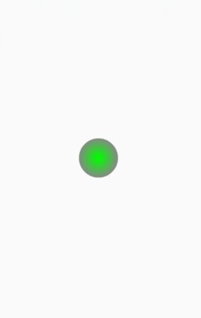
RadialGradient gradient = new RadialGradient(getMeasuredWidth() / 2, getMeasuredHeight() / 2, radius, Color.GREEN, Color.BLACK, Shader.TileMode.CLAMP);
mPaint.setShader(gradient);
canvas.drawCircle(getMeasuredWidth() / 2, getMeasuredHeight() / 2, radius, mPaint);
效果图:
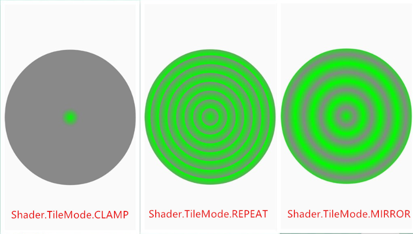
因为RadialGradient范围和canvas范围是一样大小,所以RadialGradient构造函数最后一个参数Shader.TileMode不起作用,同样的,我们来扩大canvas范围:
canvas.drawCircle(getMeasuredWidth() / 2, getMeasuredHeight() / 2, getMeasuredWidth() / 2, mPaint);
我们将圆的半径扩大至屏幕宽度的一半,然后看效果图:
再来看RadialGradient的另一个构造函数:
RadialGradient(float centerX, float centerY, float radius,int colors[], float stops[],TileMode tileMode)
和上一个不同的是colors和stops,单独列一下:
| RadialGradient参数 | 备注 |
|---|---|
| colors | color数组分布在圆的中心和边缘之间 |
| stops | 取值范围在[0.0f,1.0f],并且和colors数组中对应位置的color一一对应,如果为null,颜色均匀的分布在中心和边缘之间 |
SweepGradient
SweepGradient用来创建围绕一个中心点360度沿顺时针旋转渐变效果:
SweepGradient(float cx, float cy, int color0, int color1)
| SweepGradient参数 | 备注 |
|---|---|
| cx | 圆中心的X轴坐标 |
| cy | 圆中心的Y轴坐标 |
| color0 | 开始旋转起始颜色,起始点在3点钟方向,顺时针 |
| color1 | 结束旋转终止颜色,终止点也在3点钟方向 |
示例:
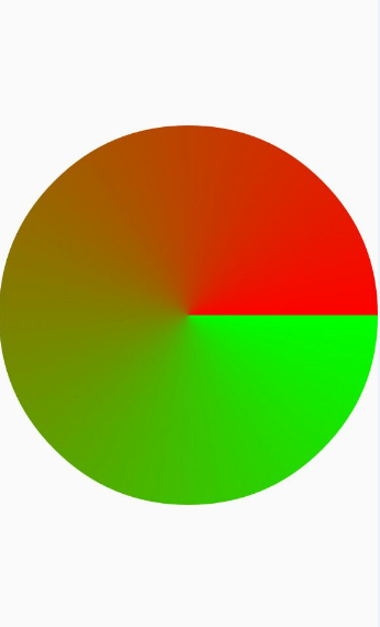
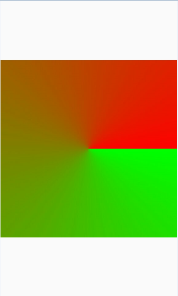
SweepGradient gradient = new SweepGradient(getMeasuredWidth() / 2, getMeasuredHeight() / 2, Color.GREEN, Color.RED);
mPaint.setShader(gradient);
canvas.drawCircle(getMeasuredWidth() / 2, getMeasuredHeight() / 2, getMeasuredWidth() / 2, mPaint);
效果图:
修改一下canvas形状
canvas.drawRect(0, (getMeasuredHeight() - getMeasuredWidth()) / 2, getMeasuredWidth(), (getMeasuredHeight() + getMeasuredWidth()) / 2, mPaint);
效果图:
SweepGradient另一个构造函数:
SweepGradient(float cx, float cy, int colors[], float positions[])
和前面不同的是colors和positions:
| SweepGradient参数 | 备注 |
|---|---|
| colors | color数组顺时针分布 |
| positions | 每个position取值范围[0,1],并且和colors数组中对应位置的color一一对应 |
示例:
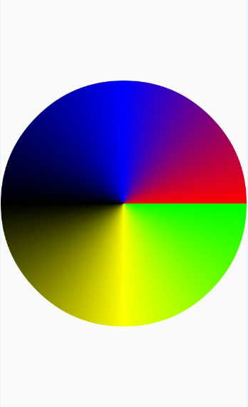
int[] colors = {Color.GREEN, Color.YELLOW, Color.BLACK, Color.BLUE, Color.RED};
float[] positions = {0.0f, 0.25f, 0.5f, 0.75f, 1.0f};
SweepGradient gradient = new SweepGradient(getMeasuredWidth() / 2, getMeasuredHeight() / 2, colors, positions);
mPaint.setShader(gradient);
canvas.drawCircle(getMeasuredWidth() / 2, getMeasuredHeight() / 2, getMeasuredWidth() / 2, mPaint);
效果图:
ComposeShader
ComposeShader结合Xfermode模式,是两个Shader的组合模式,ComposeShader有两个构造函数:
ComposeShader(Shader shaderA, Shader shaderB, PorterDuff.Mode mode)
ComposeShader(Shader shaderA, Shader shaderB, Xfermode mode)
Xfermode可以用于实现新绘制的像素与Canvas上对应位置已有的像素按照混合规则进行颜色混合,Xfermode 有三个子类:AvoidXfermode, PixelXorXfermode和PorterDuffXfermode,前两个已废弃,PorterDuffXfermode初始化时需要传入PorterDuff.Mode即:PorterDuffXfermode(PorterDuff.Mode mode),所以上面第一个构造函数是第二个构造函数的一种情况,我们只看第一个构造函数就可以了:
| ComposeShader参数 | 备注 |
|---|---|
| shaderA | 目标像素DST |
| shaderB | 源像素SRC |
| mode | 新绘制的像素与Canvas上对应位置已有的像素按照混合规则进行颜色混合 |
//在图形下面设置阴影层,产生阴影效果:
| setShadowLayer参数 | 备注 |
|---|---|
| radius | radius为阴影半径,半径越大,阴影面积越大,越模糊;反之,半径越小,阴影面积越小,也越清晰,radius=0时,阴影消失 |
| dx | dx为阴影在x轴上的偏移值 |
| dy | dy为阴影在y轴上的偏移值 |
| color | color为阴影的颜色 |
示例:
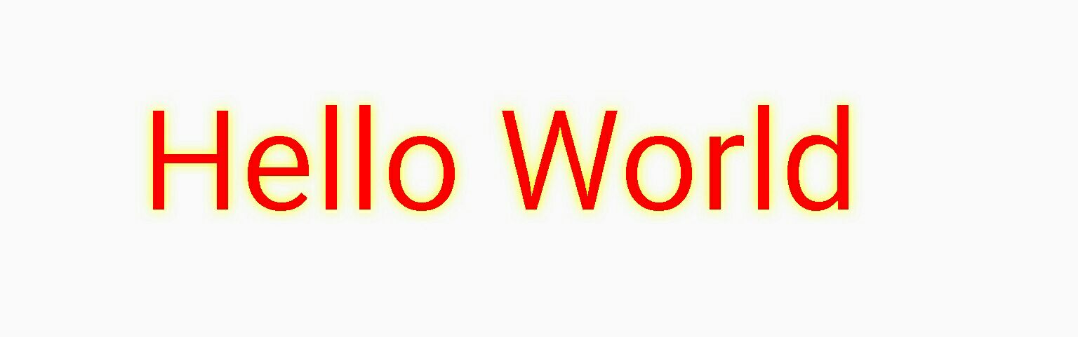
Paint paint = new Paint();
paint.setColor(Color.RED);
paint.setShadowLayer(20, 0, 0, Color.YELLOW);
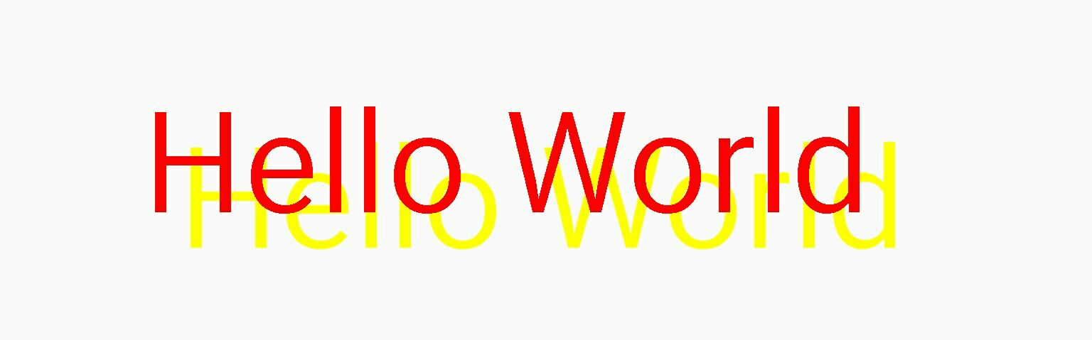
paint.setTextSize(200);
canvas.drawText("Hello World", 200, 300, paint);
效果图:
修改一下:
paint.setShadowLayer(20,50, 50, Color.YELLOW);
其他代码不变,效果图:
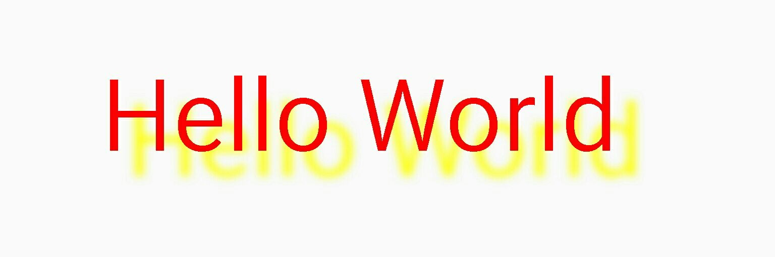
可以看到阴影偏移量起始坐标(x,y)从(0,0)变成了(50,50),即阴影位置从(0,0)移动到了(50,50)的位置,再改一下:
paint.setShadowLayer(1,50, 50, Color.YELLOW);
其他代码不变,效果图:
阴影半径radius从20变成1,可以看到阴影清晰了很多,再来改一下:
paint.setShadowLayer(0,50, 50, Color.YELLOW);
其他代码不变,效果图:
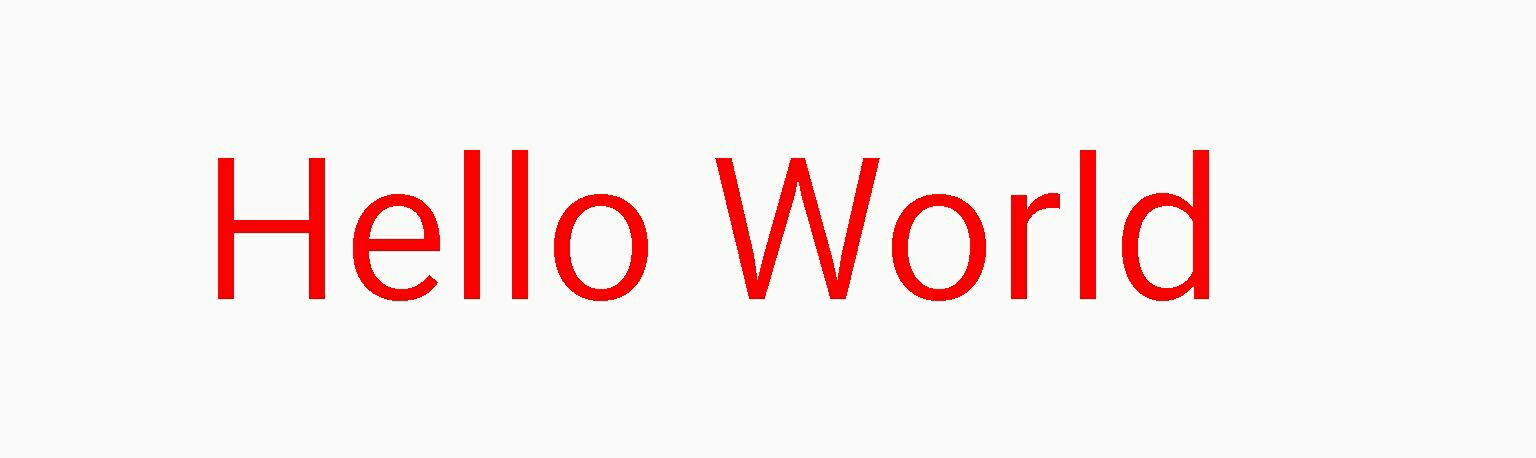
阴影半径radius变成0时,阴影消失,接着看下面代码:
Paint paint = new Paint();
paint.setColor(Color.GREEN);
paint.setShadowLayer(30, 0, 0, Color.BLACK);
canvas.drawCircle(400, 800, 100, paint);
效果图:
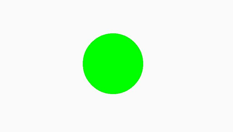
纳尼?我们预期的黑边阴影肿么没有出现?What f*ck ! 别急,只要给paint加一句:
setLayerType(LAYER_TYPE_SOFTWARE, paint);
然后来看下效果图:
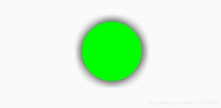
终于看到黑色阴影了,为毛要加setLayerType呢,google工程师给出解释,链接:
http://stackoverflow.com/questions/17410195/setshadowlayer-android-api-differences
Paint先介绍到这里,接下篇:
Android自定义View工具:Paint&Canvas(二)


 被折叠的 条评论
为什么被折叠?
被折叠的 条评论
为什么被折叠?
 到【灌水乐园】发言


