


The internet modules use the addresses carried in the internet header to transmit internet datagrams toward their destinations. The selection of a path for transmission is called routing.
The internet protocol uses four key mechanisms in providing its service:
- Type of Service,
- Time to Live,
- Options, and
- Header Checksum.
The internet protocol does not provide a reliable communication facility. There are no acknowledgments either end-to-end or hop-by-hop. There is no error control for data, only a header checksum. There are no retransmissions. There is no flow control.
For normal datagrams, the processing is straightforward. For incoming datagrams, the IP layer:
- verifies that the datagram is correctly formatted;
- verifies that it is destined to the local host;
- processes options;
- reassembles the datagram if necessary; and
- passes the encapsulated message to the appropriate transport-layer protocol module.
For outgoing datagrams, the IP layer:
- sets any fields not set by the transport layer;
- selects the correct first hop on the connected network (a process called "routing");
- fragments the datagram if necessary and if intentional fragmentation is implemented; and
- passes the packet(s) to the appropriate link-layer driver.
A host is said to be multihomed if it has multiple IP addresses.There are two distinct problem areas in multihoming:
- Local multihoming -- the host itself is multihomed; or
- Remote multihoming -- the local host needs to communicate with a remote multihomed host.
Addressing
A distinction is made between names, addresses, and routes. A name indicates what we seek. An address indicates where it is. A route indicates how to get there.
The internet protocol deals primarily with addresses. It is the task of higher level (i.e., host-to-host or application) protocols to make the mapping from names to addresses. The internet module maps internet addresses to local net addresses. It is the task of lower level (i.e., local net or gateways) procedures to make the mapping from local net addresses to routes.
There are now five classes of IP addresses: Class A through Class E. Class D addresses are used for IP multicasting, while Class E addresses are reserved for experimental use.
Addresses are fixed length of four octets (32 bits). An address begins with a network number, followed by local address (called the "rest" field). There are three formats or classes of internet addresses:
- in class a, the high order bit is zero, the next 7 bits are the network, and the last 24 bits are the local address;
- in class b, the high order two bits are one-zero, the next 14 bits are the network and the last 16 bits are the local address;
- in class c, the high order three bits are one-one-zero, the next 21 bits are the network and the last 8 bits are the local address.
Also, broadcasting is normally limited to a LAN, whereas multicasting can be used on a LAN or across a WAN. Indeed, applications multicast across a subset of the Internet on a daily basis.
IPv4 Class D Addresses
A multicast (Class D) address is a 28-bit logical address ( in the range 224.0.0.0 through 239.255.255.255 ) that stands for a group of hosts, and may be either permanent or transient. Permanent multicast addresses are allocated by the Internet Assigned Number Authority, while transient addresses may be allocated dynamically to transient groups. Group membership is determined dynamically using IGMP.
The low-order 28 bits of a class D address form the multicast group ID and the 32-bit address is called the group address.
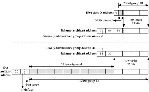
Considering just the IPv4 mapping, the high-order 24 bits of the Ethernet address are always 01:00:5e. The next bit is always 0, and the low-order 23 bits are copied from the low-order 23 bits of the multicast group address. The high-order 5 bits of the group address are ignored in the mapping. This means that 32 multicast addresses map to a single Ethernet address: The mapping is not one-to-one.
The low-order 2 bits of the first byte of the Ethernet address identify the address as a universally administered group address. Universally administered means the high-order 24 bits have been assigned by the IEEE and group addresses are recognized and handled specially by receiving interfaces.
There are a few special IPv4 multicast addresses:
- 224.0.0.1 is the all-hosts group. All multicast-capable nodes (hosts, routers, printers, etc.) on a subnet must join this group on all multicast-capable interfaces.
- 224.0.0.2 is the all-routers group. All multicast-capable routers on a subnet must join this group on all multicast-capable interfaces.
The range 224.0.0.0 through 224.0.0.255 (which we can also write as 224.0.0.0/24) is called link local. These addresses are reserved for low-level topology discovery or maintenance protocols, and datagrams destined to any of these addresses are never forwarded by a multicast router.
Scope of Multicast Addresses
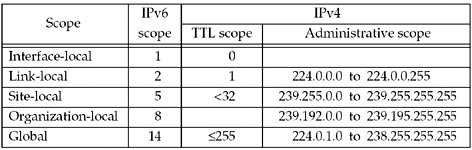
IPv4 does not have a separate scope field for multicast packets. Historically, the IPv4 TTL field in the IP header has doubled as a multicast scope field: A TTL of 0 means interface-local; 1 means link-local; up through 32 means site-local; up through 64 means region-local; up through 128 means continent-local (meaning avoiding low-rate or highly congested links, intercontinental or not); and up through 255 are unrestricted in scope (global). This double usage of the TTL field has led to difficulties
Although use of the IPv4 TTL field for scoping is accepted and recommended practice, administrative scoping is preferred when possible. This defines the range 239.0.0.0 through 239.255.255.255 as the administratively scoped IPv4 multicast space .This is the high end of the multicast address space. Addresses in this range are assigned locally by an organization, but are not guaranteed to be unique across organizational boundaries. An organization must configure its boundary routers (multicast routers at the boundary of the organization) not to forward multicast packets destined to any of these addresses.
{ <Network-number>, <Host-number> }
or
{ <Network-number>, <Subnet-number>, <Host-number> }
and the notation "-1" for a field that contains all 1 bits.
- { 0, 0 }
This host on this network. MUST NOT be sent, except as a source address as part of an initialization procedure by which the host learns its own IP address. - { 0, <Host-number> }
Specified host on this network. It MUST NOT be sent, except as a source address as part of an initialization procedure by which the host learns its full IP address. - { -1, -1 }
Limited broadcast. It MUST NOT be used as a source address.
A datagram with this destination address will be received by every host on the connected physical network but will not be forwarded outside that network.
255.255.255.255 is to be used as the destination address during the bootstrap process by applications such as BOOTP and DHCP, which do not yet know the node's IP address.
The question is: What does a host do when an application sends a UDP datagram to 255.255.255.255? Most hosts allow this (assuming the process has set the SO_BROADCAST socket option) and convert the destination address to the subnet-directed broadcast address of the outgoing interface. It is often necessary to access the datalink directly to send a packet to 255.255.255.255.
Another question is: What does a multihomed host do when the application sends a UDP datagram to 255.255.255.255? Some systems send a single broadcast on the primary interface (the first interface that was configured) with the destination IP address set to the subnet-directed broadcast address of that interface. Other systems send one copy of the datagram out from each broadcast-capable interface. For portability, however, if an application needs to send a broadcast out from all broadcast-capable interfaces, it should obtain the interface configuration and do one sendto for each broadcast-capable interface with the destination set to that interface's broadcast address.
- { <Network-number>, -1 }
Directed broadcast to the specified network. This addresses all the interfaces on the specified subnet. It MUST NOT be used as a source address.
For example, if we have the subnet 192.168.42/24, then 192.168.42.255 would be the subnet-directed broadcast address for all interfaces on the 192.168.42/24 subnet.
- { <Network-number>, <Subnet-number>, -1 }
Directed broadcast to the specified subnet. It MUST NOT be used as a source address. - { <Network-number>, -1, -1 }
Directed broadcast to all subnets of the specified subnetted network. It MUST NOT be used as a source address. - { 127, <any> }
Internal host loopback address. Addresses of this form MUST NOT appear outside a host.
The <Network-number> is administratively assigned so that its value will be unique in the entire world.
IP addresses are not permitted to have the value 0 or -1 for any of the <Host-number>, <Network-number>, or <Subnetnumber> fields (except in the special cases listed above).
This implies that each of these fields will be at least two bits long.
A host MUST support the subnet extensions to IP. As a result, there will be an address mask of the form: {-1, -1, 0} associated with each of the host’s local IP addresses;
When a host sends any datagram, the IP source address MUST be one of its own IP addresses (but not a broadcast or multicast address).
A host MUST silently discard an incoming datagram that is not destined for the host. An incoming datagram is destined for the host if the datagram’s destination address field is:
- (one of) the host’s IP address(es); or
- an IP broadcast address valid for the connected network; or
- the address for a multicast group of which the host is a member on the incoming physical interface.
The internet fragmentation and reassembly procedure needs to be able to break a datagram into an almost arbitrary number of pieces that can be later reassembled.
The receiver of the fragments uses the identification field to ensure that fragments of different datagrams are not mixed. The fragment offset field tells the receiver the position of a fragment in the original datagram. The fragment offset and length determine the portion of the original datagram covered by this fragment. The more-fragments flag indicates (by being reset) the last fragment. These fields provide sufficient information to reassemble datagrams.
The identification field is used to distinguish the fragments of one datagram from those of another. The originating protocol module of an internet datagram sets the identification field to a value that must be unique for that source-destination pair and protocol for the time the datagram will be active in the internet system. The originating protocol module of a complete datagram sets the more-fragments flag to zero and the fragment offset to zero.
To fragment a long internet datagram, an internet protocol module (for example, in a gateway), creates two new internet datagrams and copies the contents of the internet header fields from the long datagram into both new internet headers. The data of the long datagram is divided into two portions on a 8 octet (64 bit) boundary (the second portion might not be an integral multiple of 8 octets, but the first must be). Call the number of 8 octet blocks in the first portion NFB (for Number of Fragment Blocks). The first portion of the data is placed in the first new internet datagram, and the total length field is set to the length of the first datagram. The more-fragments flag is set to one. The second portion of the data is placed in the second new internet datagram, and the total length field is set to the length of the second datagram. The more-fragments flag carries the same value as the
long datagram. The fragment offset field of the second new internet datagram is set to the value of that field in the long datagram plus NFB.This procedure can be generalized for an n-way split, rather than the two-way split described.
To assemble the fragments of an internet datagram, an internet protocol module (for example at a destination host) combines internet datagrams that all have the same value for the four fields:
- identification,
- source,
- destination, and
- protocol.
The combination is done by placing the data portion of each fragment in the relative position indicated by the fragment offset in that fragment’s internet header. The first fragment will have the fragment offset zero, and the last fragment will have the more-fragments flag reset to zero.
Gateways
Gateways implement internet protocol to forward datagrams between networks. Gateways also implement the Gateway to Gateway Protocol (GGP) to coordinate routing and other internet control information.
Internet Header Format

- Version: 4 bits
A datagram whose version number is not 4 MUST be silently discarded.
- IHL: 4 bits
Internet Header Length is the length of the internet header in 32 bit words, and thus points to the beginning of the data. Note that the minimum value for a correct header is 5. - Type of Service: 8 bits
- Bits 0-2: Precedence.
111 - Network Control
The Network Control precedence designation is intended to be used within a network only. The actual use and control of that designation is up to each network.
110 - Internetwork Control
The Internetwork Control designation is intended for use by gateway control originators only.
101 - CRITIC/ECP
100 - Flash Override
011 - Flash
010 - Immediate
001 - Priority
000 - Routine
- Bit 3: 0 = Normal Delay, 1 = Low Delay.
Bits 4: 0 = Normal Throughput, 1 = High Throughput.
Bits 5: 0 = Normal Relibility, 1 = High Relibility.
Bit 6-7: Reserved for Future Use.
The use of the Delay, Throughput, and Reliability indications may increase the cost (in some sense) of the service. In many networks better performance for one of these parameters is coupled with worse performance on another. Except for very unusual cases at most two of these three indications should be set. - Total Length: 16 bits
Total Length is the length of the datagram, measured in octets, including internet header and data. This field allows the length of a datagram to be up to 65,535 octets. Such long datagrams are impractical for most hosts and networks. All hosts must be prepared to accept datagrams of up to 576 octets (whether they arrive whole or in fragments). It is recommended that hosts only send datagrams larger than 576 octets if they have assurance that the destination is prepared to accept the larger datagrams. - Identification: 16 bits
An identifying value assigned by the sender to aid in assembling the fragments of a datagram. - Flags: 3 bits
Bit 0: reserved, must be zero
Bit 1: (DF) 0 = May Fragment, 1 = Don’t Fragment.
Bit 2: (MF) 0 = Last Fragment, 1 = More Fragments. - Fragment Offset: 13 bits
This field indicates where in the datagram this fragment belongs The fragment offset is measured in units of 8 octets (64 bits). The first fragment has offset zero. - Time to Live: 8 bits
This field indicates the maximum time the datagram is allowed to remain in the internet system. If this field contains the value zero, then the datagram must be destroyed. This field is modified in internet header processing. - Protocol: 8 bits
This field indicates the next level protocol used in the data portion of the internet datagram. - Header Checksum: 16 bits
A checksum on the header only. The checksum algorithm is:
The checksum field is the 16 bit one’s complement of the one’s complement sum of all 16 bit words in the header. For purposes of computing the checksum, the value of the checksum field is zero.
A host MUST verify the IP header checksum on every received datagram and silently discard every datagram that has a bad checksum. - Source Address: 32 bits
- Destination Address: 32 bits
- Options: variable
The options may appear or not in datagrams. They must be implemented by all IP modules (host and gateways). What is optional is their transmission in any particular datagram, not their implementation.
In some environments the security option may be required in all datagrams.
The option field is variable in length. There may be zero or more options. There are two cases for the format of an option:
- Case 1: A single octet of option-type.
- Case 2: An option-type octet, an option-length octet, and the actual option-data octets. The option-length octet counts the option-type octet and the option-length octet as well as the option-data octets.
The option-type octet is viewed as having 3 fields:
1 bit copied flag,
2 bits option class,
5 bits option number.
The copied flag indicates that this option is copied into all fragments on fragmentation.
0 = not copied
1 = copied
The option classes are:
0 = control
1 = reserved for future use
2 = debugging and measurement
3 = reserved for future use
The following internet options are defined:
| CLASS | NUMBER | LENGTH | DESCRIPTION |
| 0 | 0 | End of Option list. This option occupies only 1 octet; it has no length octet. | |
| 0 | 1 | No Operation. This option occupies only 1 octet; it has no length octet. | |
| 0 | 2 | 11 | Security. Used to carry Security, Compartmentation, User Group (TCC), and Handling Restriction Codes compatible with DOD requirements. |
| 0 | 3 | var. | Loose Source Routing. Used to route the internet datagram based on information supplied by the source. |
| 0 | 9 | var. | Strict Source Routing. Used to route the internet datagram based on information supplied by the source. |
| 0 | 7 | var. | Record Route. Used to trace the route an internet datagram takes. |
| 0 | 8 | 4 | Stream ID. Used to carry the stream identifier. |
| 2 | 4 | var. | Internet Timestamp. |
00000000
Type=0
This option indicates the end of the option list. This might not coincide with the end of the internet header according to the internet header length. This is used at the end of all options, not the end of each option, and need only be used if the end of the options would not otherwise coincide with the end of the internet header.
May be copied, introduced, or deleted on fragmentation, or for any other reason.
No Operation
00000001
Type=1
This option may be used between options, for example, to align the beginning of a subsequent option on a 32 bit boundary. May be copied, introduced, or deleted on fragmentation, or for any other reason.
Security
This option provides a way for hosts to send security, compartmentation, handling restrictions, and TCC (closed user group) parameters. The format for this option is as follows:
| 10000010 | 00001011 | SSS SSS | CCC CCC | HHH HHH | TCC |
Type=130 Length=11
Security (S field): 16 bits
Specifies one of 16 levels of security (eight of which are reserved for future use).
00000000 00000000 - Unclassified
11110001 00110101 - Confidential
01111000 10011010 - EFTO
10111100 01001101 - MMMM
01011110 00100110 - PROG
10101111 00010011 - Restricted
11010111 10001000 - Secret
01101011 11000101 - Top Secret
00110101 11100010 - (Reserved for future use)
10011010 11110001 - (Reserved for future use)
01001101 01111000 - (Reserved for future use)
00100100 10111101 - (Reserved for future use)
00010011 01011110 - (Reserved for future use)
10001001 10101111 - (Reserved for future use)
11000100 11010110 - (Reserved for future use)
11100010 01101011 - (Reserved for future use)
Compartments (C field): 16 bits
An all zero value is used when the information transmitted is not compartmented. Other values for the compartments field may be obtained from the Defense Intelligence Agency.
Handling Restrictions (H field): 16 bits
The values for the control and release markings are alphanumeric digraphs and are defined in the Defense Intelligence Agency Manual DIAM 65-19, "Standard Security Markings".
Transmission Control Code (TCC field): 24 bits
Provides a means to segregate traffic and define controlled communities of interest among subscribers. The TCC values are trigraphs, and are available from HQ DCA Code 530. Must be copied on fragmentation. This option appears at most once in a datagram.
Loose Source and Record Route
| 10000011 | length | pointer | route data |
Type=131
The loose source and record route (LSRR) option provides a means for the source of an internet datagram to supply routing information to be used by the gateways in forwarding the datagram to the destination, and to record the route information.
The option begins with the option type code. The second octet is the option length which includes the option type code and the length octet, the pointer octet, and length-3 octets of route data. The third octet is the pointer into the route data indicating the octet which begins the next source address to be processed. The pointer is relative to this option, and the smallest legal value for the pointer is 4.
A route data is composed of a series of internet addresses. Each internet address is 32 bits or 4 octets. If the pointer is greater than the length, the source route is empty (and the recorded route full) and the routing is to be based on the destination address field.
If the address in destination address field has been reached and the pointer is not greater than the length, the next address in the source route replaces the address in the destination address field, and the recorded route address replaces the source address just used, and pointer is increased by four.
The recorded route address is the internet module’s own internet address as known in the environment into which this datagram is being forwarded.
This procedure of replacing the source route with the recorded route (though it is in the reverse of the order it must be in to be used as a source route) means the option (and the IP header as a whole) remains a constant length as the datagram progresses through the internet.
This option is a loose source route because the gateway or host IP is allowed to use any route of any number of other intermediate gateways to reach the next address in the route.
Must be copied on fragmentation. Appears at most once in a datagram.
Strict Source and Record Route
| 10001001 | length | pointer | route data |
Type=137
The strict source and record route (SSRR) option provides a means for the source of an internet datagram to supply routing information to be used by the gateways in forwarding the datagram to the destination, and to record the route information.
The option begins with the option type code. The second octet is the option length which includes the option type code and the length octet, the pointer octet, and length-3 octets of route data. The third octet is the pointer into the route data indicating the octet which begins the next source address to be processed. The pointer is relative to this option, and the smallest legal value for the pointer is 4.
A route data is composed of a series of internet addresses. Each internet address is 32 bits or 4 octets. If the pointer is greater than the length, the source route is empty (and the recorded route full) and the routing is to be based on the destination address field.
If the address in destination address field has been reached and the pointer is not greater than the length, the next address in the source route replaces the address in the destination address field, and the recorded route address replaces the source address just used, and pointer is increased by four.
The recorded route address is the internet module’s own internet address as known in the environment into which this datagram is being forwarded.
This procedure of replacing the source route with the recorded route (though it is in the reverse of the order it must be in to be used as a source route) means the option (and the IP header as a whole) remains a constant length as the datagram progresses through the internet.
This option is a strict source route because the gateway or host IP must send the datagram directly to the next address in the source route through only the directly connected network indicated in the next address to reach the next gateway or host specified in the route.
Must be copied on fragmentation. Appears at most once in a datagram.
Record Route
| 00000111 | length | pointer| route data |
Type=7
The record route option provides a means to record the route of an internet datagram.
The option begins with the option type code. The second octet is the option length which includes the option type code and the length octet, the pointer octet, and length-3 octets of route data. The third octet is the pointer into the route data indicating the octet which begins the next area to store a route address. The pointer is relative to this option, and the smallest legal value for the pointer is 4.
A recorded route is composed of a series of internet addresses.
Each internet address is 32 bits or 4 octets. If the pointer is greater than the length, the recorded route data area is full.
The originating host must compose this option with a large enough route data area to hold all the address expected. The size of the option does not change due to adding addresses. The intitial contents of the route data area must be zero.
When an internet module routes a datagram it checks to see if the record route option is present. If it is, it inserts its own internet address as known in the environment into which this datagram is being forwarded into the recorded route begining at the octet indicated by the pointer, and increments the pointer by four.
If the route data area is already full (the pointer exceeds the length) the datagram is forwarded without inserting the address into the recorded route. If there is some room but not enough room for a full address to be inserted, the original datagram is considered to be in error and is discarded. In either case an ICMP parameter problem message may be sent to the source host.
Not copied on fragmentation, goes in first fragment only. Appears at most once in a datagram.
Stream Identifier
| 10001000 | 00000010 | Stream ID |
Type=136 Length=4
This option provides a way for the 16-bit SATNET stream identifier to be carried through networks that do not support the stream concept.
Must be copied on fragmentation. Appears at most once in a datagram.
Internet Timestamp
| 01000100 | length | pointer | oflw | flg |
| internet address |
| timestamp |
| .... |
Type = 68
The Option Length is the number of octets in the option counting the type, length, pointer, and overflow/flag octets (maximum length 40).
The Pointer is the number of octets from the beginning of this option to the end of timestamps plus one (i.e., it points to the octet beginning the space for next timestamp). The smallest legal value is 5. The timestamp area is full when the pointer is greater than the length.
The Overflow (oflw) [4 bits] is the number of IP modules that cannot register timestamps due to lack of space.
The Flag (flg) [4 bits] values are
0 -- time stamps only, stored in consecutive 32-bit words,
1 -- each timestamp is preceded with internet address of the registering entity,
3 -- the internet address fields are prespecified. An IP module only registers its timestamp if it matches its own address with the next specified internet address.
The Timestamp is a right-justified, 32-bit timestamp in milliseconds since midnight UT. If the time is not available in milliseconds or cannot be provided with respect to midnight UT then any time may be inserted as a timestamp provided the high order bit of the timestamp field is set to one to indicate the use of a non-standard value.
The originating host must compose this option with a large enough timestamp data area to hold all the timestamp information expected. The size of the option does not change due to adding timestamps. The intitial contents of the timestamp data area must be zero or internet address/zero pairs.
If the timestamp data area is already full (the pointer exceeds the length) the datagram is forwarded without inserting the timestamp, but the overflow count is incremented by one.
If there is some room but not enough room for a full timestamp to be inserted, or the overflow count itself overflows, the original datagram is considered to be in error and is discarded. In either case an ICMP parameter problem message may be sent to the source host.
The timestamp option is not copied upon fragmentation. It is carried in the first fragment. Appears at most once in a datagram.
Padding: variable
The internet header padding is used to ensure that the internet header ends on a 32 bit boundary. The padding is zero.
Addressing
To provide for flexibility in assigning address to networks and allow for the large number of small to intermediate sized networks the interpretation of the address field is coded to specify a small number of networks with a large number of host, a moderate number of networks with a moderate number of hosts, and a large number of networks with a small number of hosts. In addition there is an escape code for extended addressing mode.
Address Formats:
| High Order Bits | Format | Class |
| 0 | 7 bits of net, 24 bits of host | a |
| 10 | 14 bits of net, 16 bits of hos | b |
| 110 | 21 bits of net, 8 bits of host | c |
| 111 | escape to extended addressing mode |
The local address, assigned by the local network, must allow for a single physical host to act as several distinct internet hosts. That is, there must be a mapping between internet host addresses and network/host interfaces that allows several internet addresses to correspond to one interface. It must also be allowed for a host to have several physical interfaces and to treat the datagrams from several of them as if they were all addressed to a single host.
Fragmentation and Reassembly.
The internet identification field (ID) is used together with the source and destination address, and the protocol fields, to identify datagram fragments for reassembly.
The More Fragments flag bit (MF) is set if the datagram is not the last fragment. The Fragment Offset field identifies the fragment location, relative to the beginning of the original unfragmented datagram. Fragments are counted in units of 8 octets. The fragmentation strategy is designed so than an unfragmented datagram has all zero fragmentation information (MF = 0, fragment offset =0). If an internet datagram is fragmented, its data portion must be broken on 8 octet boundaries.
This format allows 2**13 = 8192 fragments of 8 octets each for a total of 65,536 octets. Note that this is consistent with the the datagram total length field (of course, the header is counted in the total length and not in the fragments).
When fragmentation occurs, some options are copied, but others remain with the first fragment only.
Every internet module must be able to forward a datagram of 68 octets without further fragmentation. This is because an internet header may be up to 60 octets, and the minimum fragment is 8 octets.
Every internet destination must be able to receive a datagram of 576 octets either in one piece or in fragments to be reassembled.
The fields which may be affected by fragmentation include:
- options field
- more fragments flag
- fragment offset
- internet header length field
- total length field
- header checksum
If the Don’t Fragment flag (DF) bit is set, then internet fragmentation of this datagram is NOT permitted, although it may be discarded. This can be used to prohibit fragmentation in cases where the receiving host does not have sufficient resources to reassemble internet fragments.
One example of use of the Don’t Fragment feature is to down line load a small host. A small host could have a boot strap program that accepts a datagram stores it in memory and then executes it.
The fragmentation and reassembly procedures are most easily described by examples. The following procedures are example implementations.
General notation in the following pseudo programs: "=<" means "less than or equal", "#" means "not equal", "=" means "equal", "<-" means "is set to". Also, "x to y" includes x and excludes y; for example, "4 to 7" would include 4, 5, and 6 (but not 7).
An Example Fragmentation Procedure The maximum sized datagram that can be transmitted through the next network is called the maximum transmission unit (MTU).
If the total length is less than or equal the maximum transmission unit then submit this datagram to the next step in datagram processing; otherwise cut the datagram into two fragments, the first fragment being the maximum size, and the second fragment being the rest of the datagram. The first fragment is submitted
to the next step in datagram processing, while the second fragment is submitted to this procedure in case it is still too large.
Notation:
FO - Fragment Offset
IHL - Internet Header Length
DF - Don’t Fragment flag
MF - More Fragments flag
TL - Total Length
OFO - Old Fragment Offset
OIHL - Old Internet Header Length
OMF - Old More Fragments flag
OTL - Old Total Length
NFB - Number of Fragment Blocks
MTU - Maximum Transmission Unit
Procedure:
IF TL =< MTU THEN
Submit this datagram to the next step in datagram processing
ELSE IF DF = 1 THEN
discard the datagram
ELSE
To produce the first fragment:
- Copy the original internet header;
- OIHL <- IHL; OTL <- TL; OFO <- FO; OMF <- MF;
- NFB <- (MTU-IHL*4)/8;
- Attach the first NFB*8 data octets;
- Correct the header:
MF <- 1; TL <- (IHL*4)+(NFB*8);
Recompute Checksum;- Submit this fragment to the next step in datagram processing; To produce the second fragment:
- Selectively copy the internet header (some options are not copied, see option definitions);
- Append the remaining data;
- Correct the header:
IHL <- (((OIHL*4)-(length of options not copied))+3)/4;
TL <- OTL - NFB*8 - (OIHL-IHL)*4);
FO <- OFO + NFB; MF <- OMF; Recompute Checksum;- Submit this fragment to the fragmentation test; DONE.
In the above procedure each fragment (except the last) was made the maximum allowable size. An alternative might produce less than the maximum size datagrams. For example, one could implement a fragmentation procedure that repeatly divided large datagrams in half until the resulting fragments were less than the maximum transmission unit size.
An Example Reassembly Procedure
For each datagram the buffer identifier is computed as the concatenation of the source, destination, protocol, and identification fields. If this is a whole datagram (that is both
the fragment offset and the more fragments fields are zero), then any reassembly resources associated with this buffer identifier are released and the datagram is forwarded to the next step in datagram processing.
If no other fragment with this buffer identifier is on hand then reassembly resources are allocated. The reassembly resources consist of a data buffer, a header buffer, a fragment block bit table, a total data length field, and a timer. The data from the fragment is placed in the data buffer according to its fragment
offset and length, and bits are set in the fragment block bit table corresponding to the fragment blocks received.
If this is the first fragment (that is the fragment offset is zero) this header is placed in the header buffer. If this is the last fragment ( that is the more fragments field is zero) the
total data length is computed. If this fragment completes the datagram (tested by checking the bits set in the fragment block table), then the datagram is sent to the next step in datagram processing; otherwise the timer is set to the maximum of the current timer value and the value of the time to live field from this fragment; and the reassembly routine gives up control.
If the timer runs out, the all reassembly resources for this buffer identifier are released. The initial setting of the timer is a lower bound on the reassembly waiting time. This is because the waiting time will be increased if the Time to Live in the arriving fragment is greater than the current timer value but will not be decreased if it is less. The maximum this timer value could reach is the maximum time to live (approximately 4.25 minutes). The current recommendation for the initial timer setting is 15 seconds. This may be changed as experience with this protocol accumulates. Note that the choice of this parameter value is related to the buffer capacity available and the data rate of the transmission medium; that is, data rate times timer value equals buffer size (e.g., 10Kb/s X 15s = 150Kb).
Notation:
FO - Fragment Offset
IHL - Internet Header Length
MF - More Fragments flag
TTL - Time To Live
NFB - Number of Fragment Blocks
TL - Total Length
TDL - Total Data Length
BUFID - Buffer Identifier
RCVBT - Fragment Received Bit Table
TLB - Timer Lower Bound
Procedure:
- BUFID <- source|destination|protocol|identification;
- IF FO = 0 AND MF = 0
- THEN IF buffer with BUFID is allocated
- THEN flush all reassembly for this BUFID;
- Submit datagram to next step; DONE.
- ELSE IF no buffer with BUFID is allocated
- THEN allocate reassembly resources with BUFID;
TIMER <- TLB; TDL <- 0;- put data from fragment into data buffer with BUFID from octet FO*8 to octet (TL-(IHL*4))+FO*8;
- set RCVBT bits from FO to FO+((TL-(IHL*4)+7)/8);
- IF MF = 0 THEN TDL <- TL-(IHL*4)+(FO*8)
- IF FO = 0 THEN put header in header buffer
- IF TDL # 0
- AND all RCVBT bits from 0 to (TDL+7)/8 are set
- THEN TL <- TDL+(IHL*4)
- Submit datagram to next step;
- free all reassembly resources for this BUFID; DONE.
- TIMER <- MAX(TIMER,TTL);
- give up until next fragment or timer expires;
- timer expires: flush all reassembly with this BUFID; DONE.
In the case that two or more fragments contain the same data either identically or through a partial overlap, this procedure will use the more recently arrived copy in the data buffer and datagram delivered.
Identification
The choice of the Identifier for a datagram is based on the need to provide a way to uniquely identify the fragments of a particular datagram. The protocol module assembling fragments judges fragments to belong to the same datagram if they have the same source, destination, protocol, and Identifier. Thus, the sender must choose the Identifier to be unique for this source, destination pair and protocol for the time the datagram (or any fragment of it) could be alive in the internet.
It seems then that a sending protocol module needs to keep a table of Identifiers, one entry for each destination it has communicated with in the last maximum packet lifetime for the internet. However, since the Identifier field allows 65,536 different values, some host may be able to simply use unique identifiers independent of destination.
It is appropriate for some higher level protocols to choose the identifier. For example, TCP protocol modules may retransmit an identical TCP segment, and the probability for correct reception would be enhanced if the retransmission carried the same identifier as the original transmission since fragments of either datagram could be used to construct a correct TCP segment.
Time to Live
The time to live is set by the sender to the maximum time the datagram is allowed to be in the internet system. If the datagram is in the internet system longer than the time to live, then the datagram must be destroyed.
This field must be decreased at each point that the internet header is processed to reflect the time spent processing the datagram.
Even if no local information is available on the time actually spent, the field must be decremented by 1. The time is measured in units of seconds (i.e. the value 1 means one second). Thus, the maximum time to live is 255 seconds or 4.25 minutes. Since every module that processes a datagram must decrease the TTL by at least one even if it process the datagram in less than a second, the TTL must be thought of only as an upper bound on the time a datagram may exist. The intention is to cause undeliverable datagrams to be discarded, and to bound the maximum datagram lifetime.
Some higher level reliable connection protocols are based on assumptions that old duplicate datagrams will not arrive after a certain time elapses. The TTL is a way for such protocols to have an assurance that their assumption is met.
Options
The options are optional in each datagram, but required in implementations. That is, the presence or absence of an option is the choice of the sender, but each internet module must be able to parse every option. There can be several options present in the option field.
The options might not end on a 32-bit boundary. The internet header must be filled out with octets of zeros. The first of these would be interpreted as the end-of-options option, and the remainder as internet header padding.
Every internet module must be able to act on every option. The Security Option is required if classified, restricted, or compartmented traffic is to be passed.
Checksum
The internet header checksum is recomputed if the internet header is changed. For example, a reduction of the time to live, additions or changes to internet options, or due to fragmentation. This checksum at the internet level is intended to protect the internet header fields from transmission errors.
There are some applications where a few data bit errors are acceptable while retransmission delays are not. If the internet protocol enforced data correctness such applications could not be supported.
Errors
Internet protocol errors may be reported via the ICMP messages.
Example 1:
This is an example of the minimal data carrying internet datagram:
Example Internet Datagram
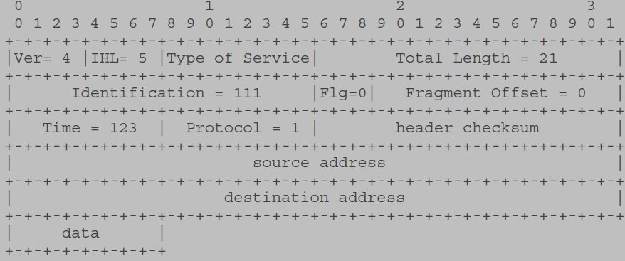
Note that each tick mark represents one bit position.
This is a internet datagram in version 4 of internet protocol; the internet header consists of five 32 bit words, and the total length of the datagram is 21 octets. This datagram is a complete datagram (not a fragment).
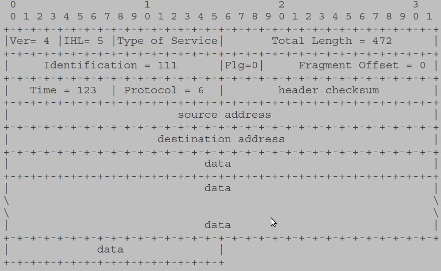
Example 2:
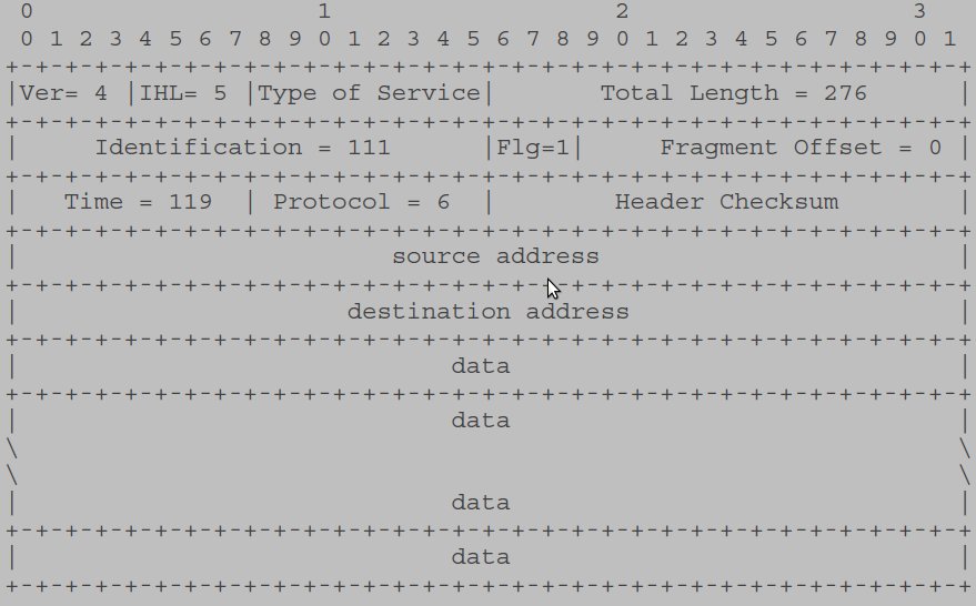
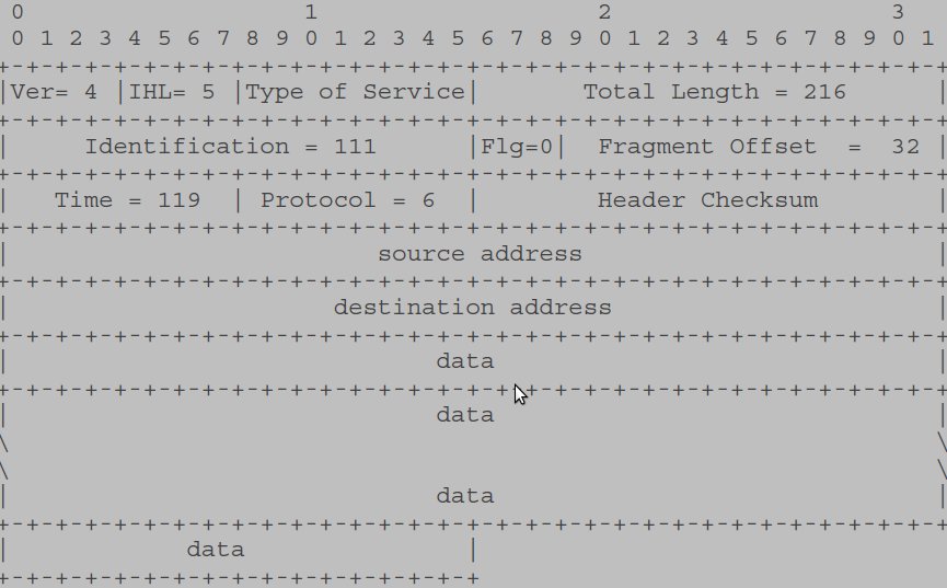
In this example, we show first a moderate size internet datagram (452 data octets), then two internet fragments that might result from the fragmentation of this datagram if the maximum sized transmission allowed were 280 octets.
Now the first fragment that results from splitting the datagram after 256 data octets.
And the second fragment.
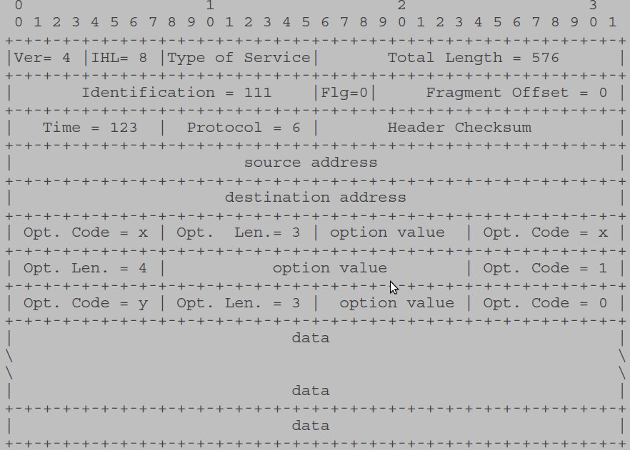
Example 3:
Here, we show an example of a datagram containing options:
Data Transmission Order
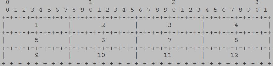
The order of transmission of the header and data described in this document is resolved to the octet level. Whenever a diagram shows a group of octets, the order of transmission of those octets is the normal order in which they are read in English. For example, in the following diagram the octets are transmitted in the order they are numbered.
Whenever an octet represents a numeric quantity the left most bit in the diagram is the high order or most significant bit. That is, the bit labeled 0 is the most significant bit. For example, the following diagram represents the value 170 (decimal).
0 1 2 3 4 5 6 7
+-+-+-+-+-+-+-+-+
|1 0 1 0 1 0 1 0|
+-+-+-+-+-+-+-+-+
Similarly, whenever a multi-octet field represents a numeric quantity the left most bit of the whole field is the most significant bit. When a multi-octet quantity is transmitted the most significant octet is transmitted first.


 6091
6091

 被折叠的 条评论
为什么被折叠?
被折叠的 条评论
为什么被折叠?
 到【灌水乐园】发言


