


实验要求:
1, RS为ISP; 只能进行IP地址配置,其所有地址均配为公有IP地址。
2,R1和R5间使用PPP的PAP认证,R5为主认证方;
R2于R5之间使用PPP的chap认证,R5为主认证方;
R3于R5之间使用HDLC封装。
3, R1/R2/R3构建一个MGRE环境,R1为中心站点; R1. R4间为点到点的GRE。
4,整个私有网络基于RIP全网可达。
5.所有PC设罢私有Ip为源IP,可以访问5环回。
一、搭建拓扑图并分配IP完成基础配置
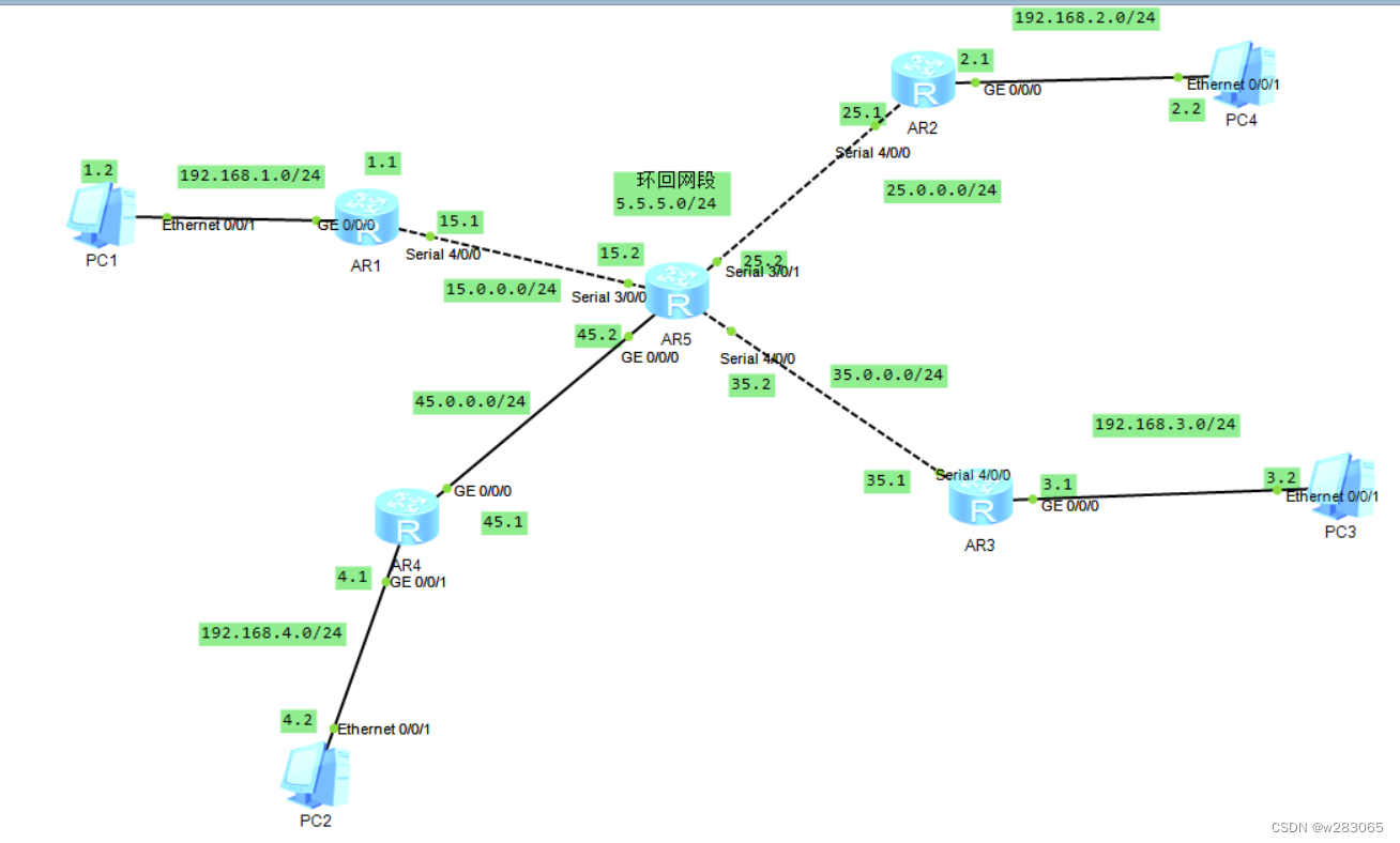
首先对各个接口配置IP
[r1-GigabitEthernet0/0/0]ip add 192.168.1.1 24
[r1-Serial4/0/0]ip add 10.0.0.1 24
[r2-GigabitEthernet0/0/0]ip add 192.168.2.1 24
[r2-Serial4/0/0]ip add 15.0.0.1 24
[r3-GigabitEthernet0/0/0]ip add 192.168.3.1 24
[r3-Serial4/0/0]ip add 20.0.0.1 24
[r4-GigabitEthernet0/0/0]ip add 192.168.4.1 24
[r4-GigabitEthernet0/0/1]ip add 25.0.0.1 24
[isp-Serial3/0/0]ip add 10.0.0.2 24
[isp-Serial3/0/1]ip add 15.0.0.2 24
[isp-Serial4/0/0]ip add 20.0.0.2 24
[isp-GigabitEthernet0/0/0]ip add 25.0.0.2 24
[isp-LoopBack0]ip add 5.5.5.1 24
二、①R1和R5间使用PPP的PAP认证,R5为主认证方
对认证方r5配置
在AAA中申请用户名和密码
[isp-aaa]local-user huawei password cipher 12345
[isp-aaa]local-user huawei service-type ppp
在接口做PAP认证
[isp-Serial3/0/0]ppp authentication-mode pap
被认证方r1
[r1-Serial4/0/0]ppp pap local-user huawei password cipher 12345
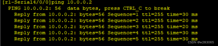
PPP会话是一次性会话,会话一旦建立,再配置认证将不生效,再下次会话建立时 才生效
所以我们此时可以重新关闭接口,然后重启,此时如果仍然可以ping通证明认证成功
②R2于R5之间使用PPP的chap认证,R5为主认证方;
认证方r5
在AAA中申请用户名和密码
[isp-aaa]local-user admin password cipher 12345
[isp-aaa]local-user admin service-type ppp
在接口做PAP认证
[isp-Serial3/0/1]ppp authentication-mode chap
被认证方r2
[r2-Serial4/0/0]ppp chap user admin
[r2-Serial4/0/0]ppp chap password cipher 12345
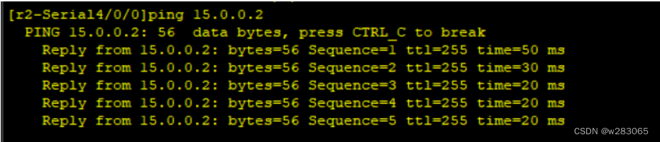
重启测试
[r2-Serial4/0/0]shutdown
[r2-Serial4/0/0]undo shutdown
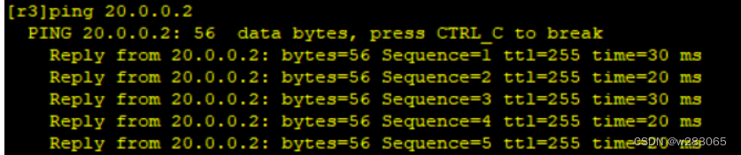
③R3于R5之间使用HDLC封装
将两个接口都改为hdlc
[r3-Serial4/0/0]link-protocol hdlc
Warning: The encapsulation protocol of the link will be changed. Continue? [Y/N]
:y
[isp-Serial4/0/0]link-protocol hdlc
三、R1/R2/R3构建一个MGRE环境,R1为中心站点;R1、R4间为点到点的GRE。
R1、R4间为点到点的GRE
创建一条隧道网段为192.168.6.0 24
对r1
1,创建隧道接口
[R1]interface Tunnel 0/0/1
2,隧道接口配置IP地址
[r1-Tunnel0/0/1]ip add 192.168.6.1 24
3,定义封装方式
[r1-Tunnel0/0/1]tunnel-protocol gre
4,定义封装内容
[r1-Tunnel0/0/1]source 10.0.0.1
[r1-Tunnel0/0/1]description 25.0.0.1
对r4
1,创建隧道接口
[R4]interface Tunnel 0/0/1
2,隧道接口配置IP地址
[r4-Tunnel0/0/1]ip add 192.168.6.2 24
3,定义封装方式
[r4-Tunnel0/0/1]tunnel-protocol gre
4,定义封装内容
[r4-Tunnel0/0/1]source 25.0.0.1
[r4-Tunnel0/0/1]description 10.0.0.1
R1/R2/R3构建一个MGRE环境,R1为中心站点
创建隧道,然后设定的虚拟网段为192.168.5.0
对中心r1进行配置
1,创建隧道接口
[r1]int Tunnel 0/0/0
2,隧道接口配置IP地址
[r1-Tunnel0/0/0]ip add 192.168.5.1 24
3,定义封装方式
[r1-Tunnel0/0/0]tunnel-protocol gre p2mp
4,定义封装的源IP
[r1-Tunnel0/0/0]source 10.0.0.1
5,创建NHRP域
[r1-Tunnel0/0/0]nhrp network-id 100
r2
1,创建隧道接口
[r2]int Tunnel 0/0/0
2,隧道接口配置IP地址
[r1-Tunnel0/0/0]ip add 192.168.5.2 24
3,定义封装方式
[r1-Tunnel0/0/0]tunnel-protocol gre p2mp
4,定义封装的源IP
[r1-Tunnel0/0/0]source s 4/0/0
5,加入NHRP域
[r2-Tunnel0/0/0]nhrp network-id 100
6,找中心上报映射信息
[r2-Tunnel0/0/0]nhrp entry 192.168.5.1 10.0.0.1 register
r3
1,创建隧道接口
[r3]int Tunnel 0/0/0
2,隧道接口配置IP地址
[r3-Tunnel0/0/0]ip add 192.168.5.3 24
3,定义封装方式
[r3-Tunnel0/0/0]tunnel-protocol gre p2mp
4,定义封装的源IP
[r3-Tunnel0/0/0]source s 4/0/0
5,加入NHRP域
[r3-Tunnel0/0/0]nhrp network-id 100
6,找中心上报映射信息
[r3-Tunnel0/0/0]nhrp entry 192.168.5.1 10.0.0.1 register
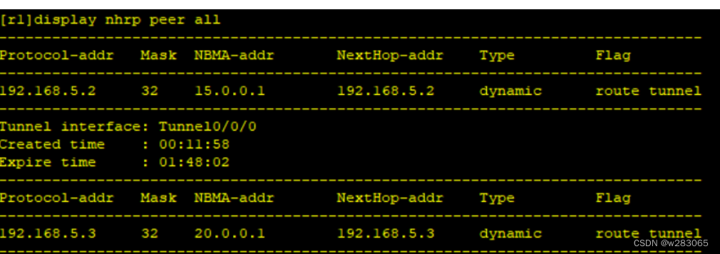
查看nhrp信息
四、整个私有网络基于RIP全网可达
对r1 2 3 4 进行配置
[r1]rip
[r1-rip-1]v 2
[r1-rip-1]network 192.168.1.0
[r1-rip-1]network 192.168.5.0
[r1-rip-1]network 192.168.6.0
[r2]rip
[r2-rip-1]v 2
[r2-rip-1]network 192.168.2.0
[r2-rip-1]network 192.168.5.0
[r3]rip
[r3-rip-1]v 2
[r3-rip-1]network 192.168.3.0
[r3-rip-1]network 192.168.5.0
[r4]rip
[r4-rip-1]v 2
[r4-rip-1]network 192.168.4.0
[r4-rip-1]network 192.168.6.0
只有r1r1通过rip获得了各个网段的路由,而其他路由器并未获得原因是:MGRE环境是一种类似于NBMA的环境,不支持组播。
解决方法:关闭水平分割
[r1-Tunnel0/0/0]undo rip split-horizon


 128
128


 被折叠的 条评论
为什么被折叠?
被折叠的 条评论
为什么被折叠?
 到【灌水乐园】发言


