


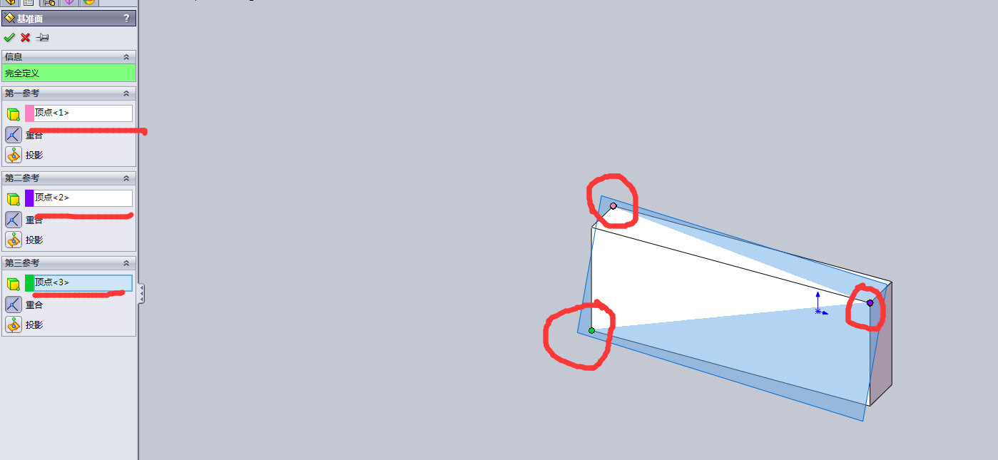
一 :三点创建一个平面
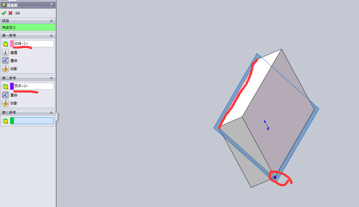
二 :一个点一条线创建一个平面
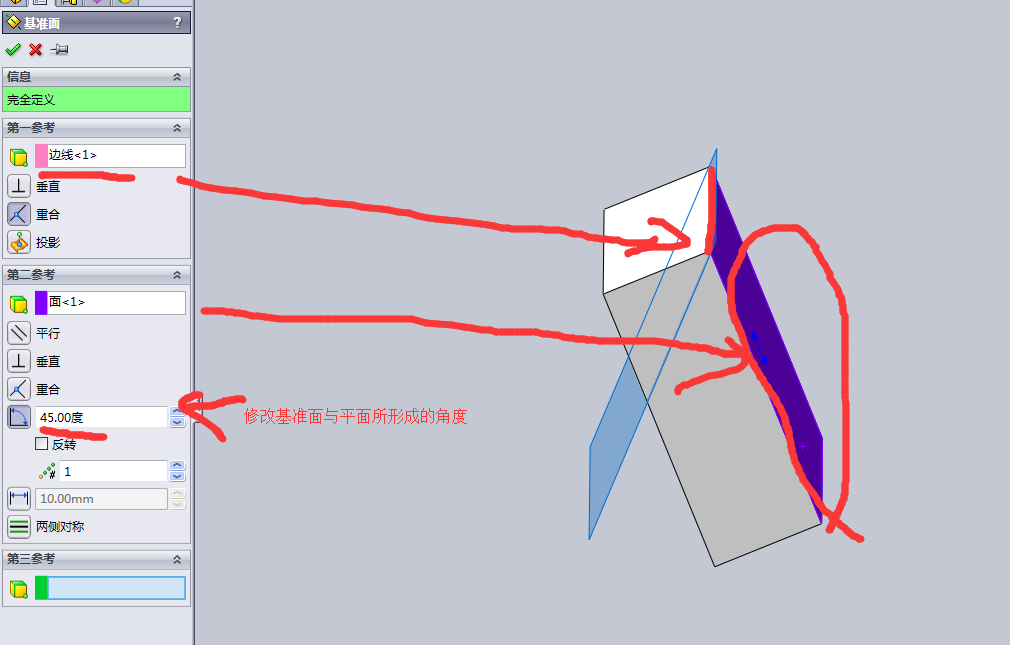
三 :线面角度创建平面
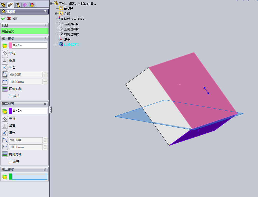
四 :面面角度创建平面
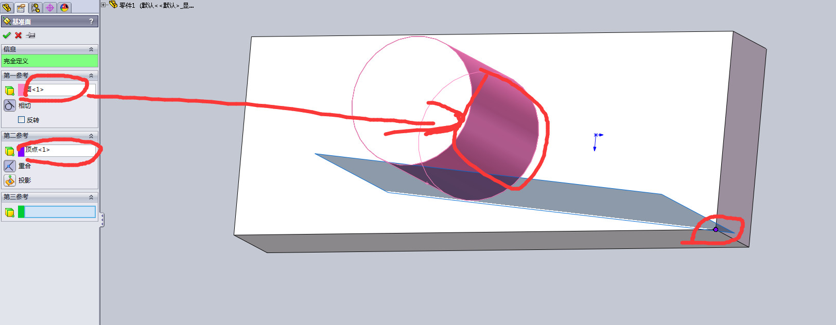
五 :曲面与点创建平面
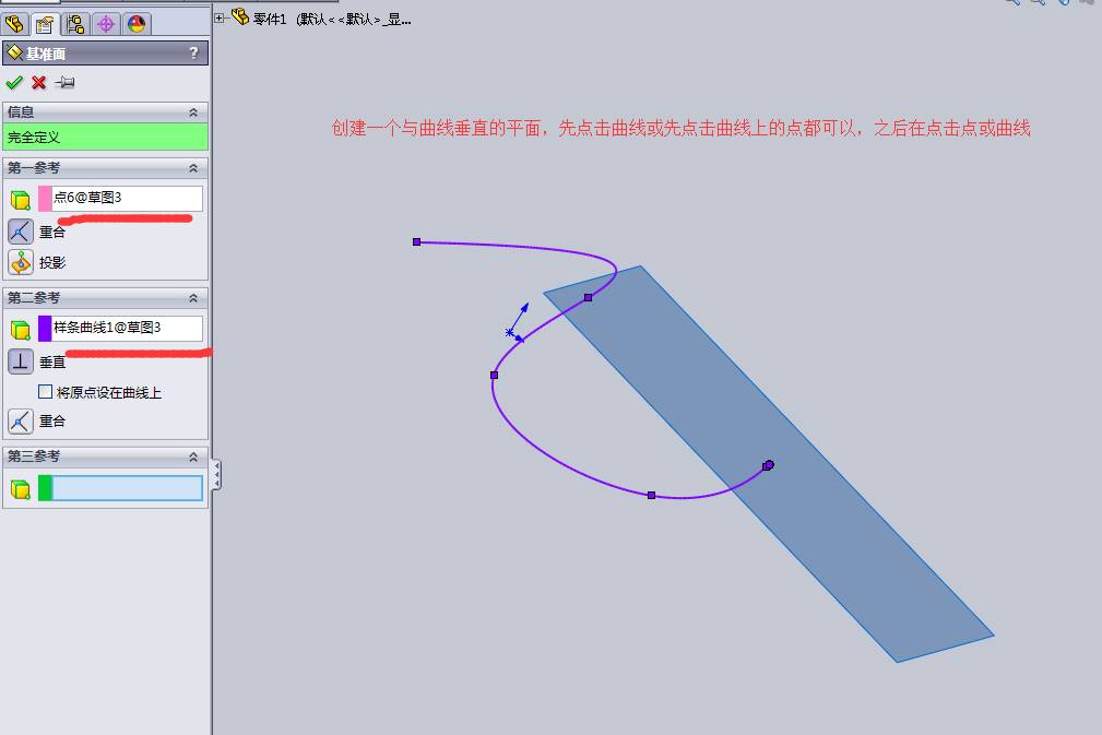
六 :曲线与点创建平面

一 :三点创建一个平面
二 :一个点一条线创建一个平面
三 :线面角度创建平面
四 :面面角度创建平面
五 :曲面与点创建平面
六 :曲线与点创建平面
转载于:https://www.cnblogs.com/2277098974-qqcom/p/7985172.html
 659
186
659
186

 被折叠的 条评论
为什么被折叠?
被折叠的 条评论
为什么被折叠?
 到【灌水乐园】发言


