


Problem Statement
In armature-controlled DC motors, the applied voltage Va controls the angular velocity w of the shaft.
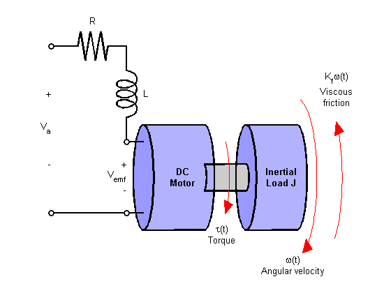
This example shows two DC motor control techniques for reducing the sensitivity of w to load variations (changes in the torque opposed by the motor load).
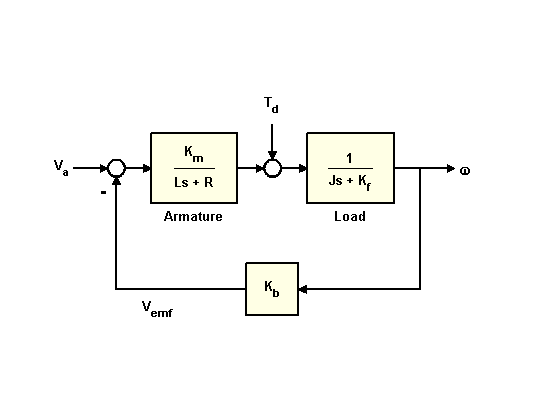
A simplified model of the DC motor is shown above. The torque Td models load disturbances. You must minimize the speed variations induced by such disturbances.
For this example, the physical constants are:
R = 2.0; % Ohms
L = 0.5; % Henrys
Km = 0.1; % torque constant
Kb = 0.1; % back emf constant
Kf = 0.2; % Nms
J = 0.02; % kg.m^2/s^2
First construct a state-space model of the DC motor with two inputs (Va,Td) and one output (w):
h1 = tf(Km,[L R]); % armature
h2 = tf(1,[J Kf]); % eqn of motion
dcm = ss(h2) * [h1 , 1]; % w = h2 * (h1*Va + Td)
dcm = feedback(dcm,Kb,1,1); % close back emf loop
Note: Compute with the state-space form to minimize the model order.
Now plot the angular velocity response to a step change in voltage Va:
stepplot(dcm(1));
 最低0.47元/天 解锁文章


 1568
1568


 被折叠的 条评论
为什么被折叠?
被折叠的 条评论
为什么被折叠?
 到【灌水乐园】发言


