


三层交换机配置ACL(访问控制列表)
说明:书本上讲述的ACL主要是应用在路由器上,但现在三层交换机在大中型企业中的应用越来越广泛,三层交换机因拥有路由器的功能而逐渐代替路由器。ACL访问控制列表是构建安全规范的网络不可缺少的,但在三层交换机上配置ACL却不为一些刚进企业的初级网络管理维护人员所知。在这里我介绍一下在三层交换机上配置ACL的试验过程。
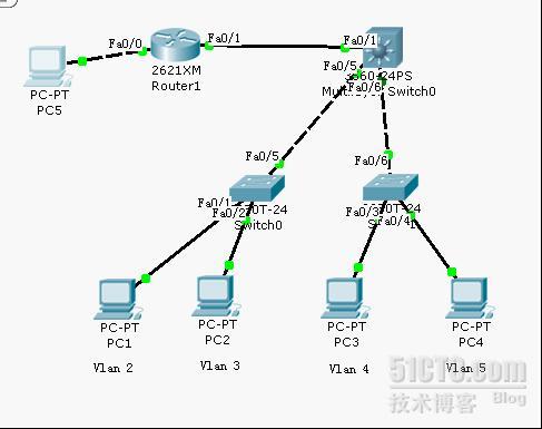
试验拓扑介绍:
三层交换机上配置本地Vlan 实现下层接入层交换机不同Vlan互通。
PC1 192.168.20.10 VLAN 192.168.20.1
PC2 192.168.30.20 VLAN 192.168.30.1
PC3 192.168.40.30 VLAN 192.168.40.1
PC4 192.168.50.40 VLAN 192.168.50.1
F0/1 192.168.70.2 (开启路由功能)
路由器上配置
F0/0 192.168.60.1 PC5 192.168.60.50
F0/1 192.168.70.1
试验步骤:
1、 在二层交换机上把相应的PC加入VLAN
查看交换机Switch0
Switch0(config)#show run
!
interface FastEthernet0/1
switchport access vlan 2
!
interface FastEthernet0/2
switchport access vlan 3
!
查看交换机Switch1
Switch1#show run
!
interface FastEthernet0/3
switchport access vlan 4
!
interface FastEthernet0/4
switchport access vlan 5
!
2、 在三层交换机上配置相应的本地VALN
Switch(config)#inter vl 2
Switch(config-if)#ip add 192.168.20.1 255.255.255.0
Switch(config-if)#no shut
Switch(config)#inter vl 3
Switch(config-if)#ip add 192.168.30.1 255.255.255.0
Switch(config-if)#no shut
Switch(config)#inter vl 4
Switch(config-if)#ip add 192.168.40.1 255.255.255.0
Switch(config-if)#no shut
Switch(config)#inter vl 5
Switch(config-if)#ip add 192.168.50.1 255.255.255.0
Switch(config-if)#no shut
Switch(config-if)#exi
在接口itnerface f0/1上开启路由接口
Switch(config)#inter f0/1
Switch(config-if)#no switchport
3、 在二层交换机和三层交换机之间开启中继链路
4、 在路由器和三层交换机上配置动态路由协议RIP
Router(config)#router rip
Router(config)#network 192.168.60.0
Router(config)# network 192.168.70.0
三层交换机上配置
Switch(config)#router rip
Switch(config-router)#ne
Switch(config-router)#network 192.168.70.0
Switch(config-router)#network 192.168.20.0
Switch(config-router)#network 192.168.30.0
Switch(config-router)#network 192.168.40.0
Switch(config-router)#network 192.168.50.0
Switch(config-router)#
5、 验证各PC互通
PC>ping 192.168.30.20
Pinging 192.168.30.20 with 32 bytes of data:
Request timed out.
Reply from 192.168.30.20: bytes=32 time=110ms TTL=126
Reply from 192.168.30.20: bytes=32 time=110ms TTL=126
Reply from 192.168.30.20: bytes=32 time=125ms TTL=126
Ping statistics for 192.168.30.20:
Packets: Sent = 4, Received = 3, Lost = 1 (25% loss),
Approximate round trip times in milli-seconds:
Minimum = 110ms, Maximum = 125ms, Average = 115ms
PC>ping 192.168.40.30
Pinging 192.168.40.30 with 32 bytes of data:
Reply from 192.168.40.30: bytes=32 time=94ms TTL=126
Reply from 192.168.40.30: bytes=32 time=125ms TTL=126
Reply from 192.168.40.30: bytes=32 time=125ms TTL=126
Reply from 192.168.40.30: bytes=32 time=109ms TTL=126
Ping statistics for 192.168.40.30:
Packets: Sent = 4, Received = 4, Lost = 0 (0% loss),
Approximate round trip times in milli-seconds:
Minimum = 94ms, Maximum = 125ms, Average = 113ms
6、 在三层交换机上配置ACL
注意如果设置不同VALN的PC之间不能互通,则应用的接口应为VLAN对应的本地Llan接口。
设置PC1不能ping通PC3和PC4
Switch(config)#access-list 10 deny host 192.168.20.10
应用于接口
Switch(config)#inter vl 4
Switch(config-if)#ip access-group 10 out
Switch(config-if)#exi
Switch(config)#inter vl 5
Switch(config-if)#ip access-group 10 out
Switch(config-if)#
或者是
Switch(config)#inter vl 2
Switch(config-if)#ip access-group 10 in
Switch(config-if)#
(注上:此处ACL应用于接口,从PC1到PC3 和PC4,数据流走向是经过三层交换机上配置的本地Vlan2接口进入,再从三层交换机上配置的本地Vlan4出去到达PC3,从本地Vlan5出去到达PC4。所以在配置ACL时应注意访问控制列表应用于哪儿接口?!)
7、 验证:
PC1不能ping通PC3和PC4
PC>ping 192.168.50.40
Pinging 192.168.50.40 with 32 bytes of data:
Request timed out.
Request timed out.
Ping statistics for 192.168.50.40:
Packets: Sent = 3, Received = 0, Lost = 3 (100% loss),
Control-C
^C
PC>ping 192.168.40.30
Pinging 192.168.40.30 with 32 bytes of data:
Request timed out.
Request timed out.
Request timed out.
Request timed out.
容易发生的错误分析:可能在学习的时候只是学习了如何在路由器上配置ACL,而不知道在三层交换机上也能配置ACL。或许有些同学在三层交换机上各接口开启路由接口模式,就把三层交换机当作路由器来配置,虽说三层交换机有路由器的功能,但是一些协议运用起来还是和路由器有差别的。
就比如说这个试验在三层交换机的下连接口f0/5和f0/6上开启路由接口模式,结果是不配置ACL的前提下,各Vlan不通。所以f0/5和f0/6不能开启路由接口模式。在Vlan 2、3、4、5之间配置ACL时,要弄清楚数据流的进、出接口,在这里Vlan2、3、4、5之间的数据流的进、出口就是在三层交换机上配置本地Vlan接口。
其实ACL原理都一样、只要清楚三层交换机上配置ACL和路由器上配置的区别,在三层交换机上配置ACL就简单易行。

转载于:https://blog.51cto.com/yuanliujun/391796


 2714
2714


 被折叠的 条评论
为什么被折叠?
被折叠的 条评论
为什么被折叠?
 到【灌水乐园】发言


