


我有一个预感,看了我前几篇教程的人,可能会问我:这是一系列3D教程,为什么讲的都是2D的事呢?那么在接下来这篇教程中,我们来创建一些3D的渲染网格。这也是后面的教程所需要的准备。
在当初我开始学习openGL的时候,我也很困惑如何用编程方式取实现立方体,圆锥体等等。我想要它很容易的能够被集成到我的场景中。所以这篇教程将会讲解如何创建一些初级的立体模型。这可能不是效率最高的方式,但是确实是能够实现的一种方式。
设计
设计一个openGL 框架之初,最好是绘制组合图。如下是我如何开始的示意图:
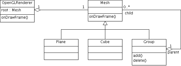
让我们开始制造这些组合吧。
Mesh
为渲染的网格创建一个基础类是个不错的主意。就让我们从创建一个叫Mesh的类开始。
package se.jayway.opengl.tutorial.mesh;
public class Mesh {

}
我们从之前的例子里拷贝过draw方法,由于我在教程一中写过这个方法,所以我这里只展示一下:
    // 顶点缓冲
    private FloatBuffer verticesBuffer = null;

    // 渲染顺序缓冲
    private ShortBuffer indicesBuffer = null;

    // 顺序缓冲的数量
    private int numOfIndices = -1;

    // 纯色
    private float[] rgba = new float[]{1.0f, 1.0f, 1.0f, 1.0f};

    // 渐变色
    private FloatBuffer colorBuffer = null;

    public void draw(GL10 gl) {
        // 逆时针
	gl.glFrontFace(GL10.GL_CCW);
	// 开启裁剪
	gl.glEnable(GL10.GL_CULL_FACE);
	// 背面裁剪
	gl.glCullFace(GL10.GL_BACK);
	// 、开启渲染中使用的顶点缓冲
	gl.glEnableClientState(GL10.GL_VERTEX_ARRAY);
	// 指定顶点缓冲的位置和格式

	gl.glVertexPointer(3, GL10.GL_FLOAT, 0, verticesBuffer);
        // 设置纯色
        gl.glColor4f(rgba[0], rgba[1], rgba[2], rgba[3]);
        //渐变色
        if ( colorBuffer != null ) {
            // 开启颜色缓冲
            gl.glEnableClientState(GL10.GL_COLOR_ARRAY);
            // 指定颜色缓冲的位置
            gl.glColorPointer(4, GL10.GL_FLOAT, 0, colorBuffer);
        }
	gl.glDrawElements(GL10.GL_TRIANGLES, numOfIndices,
		GL10.GL_UNSIGNED_SHORT, indicesBuffer);
	// 禁用顶点缓冲
	gl.glDisableClientState(GL10.GL_VERTEX_ARRAY);
	// 禁用面裁剪
	gl.glDisable(GL10.GL_CULL_FACE);
    }
我们需要子类能够设置顶点和渲染顺序的方法,这些方法没有什么新的东西,和你之前在教程里看到的几乎一样。
    protected void setVertices(float[] vertices) {
	// float为4字节,所以乘以4
	ByteBuffer vbb = ByteBuffer.allocateDirect(vertices.length * 4);
	vbb.order(ByteOrder.nativeOrder());
	verticesBuffer = vbb.asFloatBuffer();
	verticesBuffer.put(vertices);
	verticesBuffer.position(0);
    }

    protected void setIndices(short[] indices) {
	// short为2字节,所以长度乘以2
	ByteBuffer ibb = ByteBuffer.allocateDirect(indices.length * 2);
	ibb.order(ByteOrder.nativeOrder());
	indicesBuffer = ibb.asShortBuffer();
	indicesBuffer.put(indices);
	indicesBuffer.position(0);
	numOfIndices = indices.length;
    }

    protected void setColor(float red, float green, float blue, float alpha) {
        // 设置纯色
        rgba[0] = red;
        rgba[1] = green;
        rgba[2] = blue;
        rgba[3] = alpha;
    }

    protected void setColors(float[] colors) {

	ByteBuffer cbb = ByteBuffer.allocateDirect(colors.length * 4);
	cbb.order(ByteOrder.nativeOrder());
	colorBuffer = cbb.asFloatBuffer();
	colorBuffer.put(colors);
	colorBuffer.position(0);
    }
我需要添加一些东西。当我们要处理多个网格时,我们需要能够独立的移动和旋转他们,所以我们增加旋转和平移的操作变量:
    // 平移参数
    public float x = 0;
    public float y = 0;
    public float z = 0;

    // 旋转参数
    public float rx = 0;
    public float ry = 0;
    public float rz = 0;
并在draw方法中在调用gl.glDrawElements之前使用这些参数:
    gl.glTranslatef(x, y, z);
    gl.glRotatef(rx, 1, 0, 0);
    gl.glRotatef(ry, 0, 1, 0);
    gl.glRotatef(rz, 0, 0, 1);
平面
让我们开始创建一个平面,你也许会认为是个简单的任务,实际上也如此。但是为了让它更有趣,更有用,我们要使用一些不同的设置来创建它,比如宽度,深度,多少个宽的片元,多少个深的片元(这里用的词直接翻译过来是碎片,意思是组成平面的元素-——译者注)。
在下文中,我所说的宽是指x轴方向的长度,深度是指Z轴方向,高是指Y轴方向。

片元是指长度上被分为多少个部分。这对于你创建一个不是一个整体的平面是很有用的。如果你创建一个xy上的平面,z不全为0,取值为-0.1到0.1之间的随机数,你将会得到一个你可以用在游戏中做 为地面的平面,当然你的放上漂亮的纹理。
看下图,不同的碎片组合成不同的平面,由于我们需要三角形,所以我们把他们拆分为两个三角形。
我讨厌那些没有简单方法初始化的框架和没有简单构造方法的类,所以我会在类里尽量写至少一个构造方法。我给plane的构造方法是:
//创建一个平面,宽高各为1单位,即一个片元.
public Plane()
一个简单的改变大小的方法:
 // 让你能够定义宽高,但是仍然是一个片元
public Plane(float width, float height)
最后是一个带不同参数的构造方法:
// 所有的设置参数
public Plane(float width, float height, int widthSegments, int heightSegments)
如果我定义一个平面在宽高方向上各有4个这样的宽高为1单位的片元,那么看起来应该是这样:

上图中,左图是表示这个平面上的片元,右图表示我们实际上创建的平面的样子。
package se.jayway.opengl.tutorial.mesh;

public class Plane extends Mesh {

    public Plane() {
	this(1, 1, 1, 1);
    }

    public Plane(float width, float height) {
	this(width, height, 1, 1);
    }

    public Plane(float width, float height, int widthSegments,
		int heightSegments) {
	float[] vertices = new float[(widthSegments + 1) * (heightSegments + 1)
			* 3];
	short[] indices = new short[(widthSegments + 1) * (heightSegments + 1)
			* 6];

	float xOffset = width / -2;
	float yOffset = height / -2;
	float xWidth = width / (widthSegments);
	float yHeight = height / (heightSegments);
	int currentVertex = 0;
	int currentIndex = 0;
	short w = (short) (widthSegments + 1);
	for (int y = 0; y < heightSegments + 1; y++) {
            for (int x = 0; x < widthSegments + 1; x++) {
	        vertices[currentVertex] = xOffset + x * xWidth;
		vertices[currentVertex + 1] = yOffset + y * yHeight;
		vertices[currentVertex + 2] = 0;
		currentVertex += 3;

		int n = y * (widthSegments + 1) + x;

		if (y < heightSegments && x < widthSegments) {
		    // Face one
		    indices[currentIndex] = (short) n;
		    indices[currentIndex + 1] = (short) (n + 1);
		    indices[currentIndex + 2] = (short) (n + w);
		    // Face two
		    indices[currentIndex + 3] = (short) (n + 1);
		    indices[currentIndex + 4] = (short) (n + 1 + w);
		    indices[currentIndex + 5] = (short) (n + 1 + w - 1);

		    currentIndex += 6;
		}
	    }
	}

	setIndices(indices);
	setVertices(vertices);
    }
}
立方体
下一步我觉得应该创建一个立方体了。我将会创建一个简单的立方体,你可以设置宽高深,但是我建议你像我们在创建平面时一样操作,把这个当做一个练习。
构造方法像下面这样:
public Cube(float width, float height, float depth)由于我没有使用片元,所以构造方法会很简单。
package se.jayway.opengl.tutorial.mesh;

public class Cube extends Mesh {
    public Cube(float width, float height, float depth) {
        width  /= 2;
        height /= 2;
        depth  /= 2;

        float vertices[] = { -width, -height, -depth, // 0
                              width, -height, -depth, // 1
                              width,  height, -depth, // 2
                             -width,  height, -depth, // 3
                             -width, -height,  depth, // 4
                              width, -height,  depth, // 5
                              width,  height,  depth, // 6
                             -width,  height,  depth, // 7
        };

        short indices[] = { 0, 4, 5,
                            0, 5, 1,
                            1, 5, 6,
                            1, 6, 2,
                            2, 6, 7,
                            2, 7, 3,
                            3, 7, 4,
                            3, 4, 0,
                            4, 7, 6,
                            4, 6, 5,
                            3, 0, 1,
                            3, 1, 2, };

        setIndices(indices);
        setVertices(vertices);
    }
}
如果你想要使用片元来做,那么构造方法应该是这样的:
public Cube(float width, float height, float depth,
                 int widthSegments, int heightSegments, int depthSegments)
现在我们有了Plane来替换Square类(教程二中的代码),我删除它,在Renderer类中把Square改成Cube。
public OpenGLRenderer() {
    // 初始化cube
    cube = new Cube(1, 1, 1);
    cube.rx = 45;
    cube.ry = 45;
}
然后渲染它:
public void onDrawFrame(GL10 gl) {
    ...
    // 绘制cube
    cube.draw(gl);
}
分组-group
”group“是很适合去初始化和控制3D场景的。group做的是分发所有的命令到它其中的子元素中。下面是group的简单实现:
package se.jayway.opengl.tutorial.mesh;

import java.util.Vector;

import javax.microedition.khronos.opengles.GL10;

public class Group extends Mesh {
    private Vector<mesh> children = new Vector<mesh>();

    @Override
    public void draw(GL10 gl) {
        int size = children.size();
        for( int i = 0; i < size; i++)
            children.get(i).draw(gl);
    }

    public void add(int location, Mesh object) {
        children.add(location, object);
    }

    public boolean add(Mesh object) {
        return children.add(object);
    }

    public void clear() {
        children.clear();
    }

    public Mesh get(int location) {
        return children.get(location);
    }

    public Mesh remove(int location) {
        return children.remove(location);
    }

    public boolean remove(Object object) {
        return children.remove(object);
    }

    public int size() {
        return children.size();
    }
}
将cube添加到group中,并将group作为根结点,交给renderer渲染。
Group group = new Group();
Cube cube = new Cube(1, 1, 1);
cube.rx = 45;
cube.ry = 45;
group.add(cube);
root = group;
渲染我们的场景:
public void onDrawFrame(GL10 gl) {
    ...
    // Draw our scene.
    root.draw(gl);
}
建议
当你开始一个新项目的时候,创建一些基础类是个不错的主意。以我的经验,当你开始编码的时候,十次有九次,你没有从美工那里拿到任何可以渲染的东西,所以保留一些网格作为占位符还是不错的。我会告诉你我的做法,这样你可以自己创建自己的基础网格类库。
创建你自己的网格类库,也是了解顶点和渲染顺序的好方式。
圆锥体
当你完成了立方体,然后我建议你去创建圆锥体。圆锥体并不是简单的圆锥体,如果你只创建了三四个面,那么看起来可能像个金字塔形的东西,如果顶部和底部的半径一样,那就成了一个圆柱体。这就是为什么圆锥体这么重要。如下图,圆锥体能够做成什么样。

public Cone(float baseRadius, float topRadius, float height, int numberOfSides)金字塔
public class Pyramid extends Cone {
    public Pyramid(float baseRadius, float height)  {
        super(baseRadius, 0, height, 4);
    }
}
圆柱体
public class Cylinder extends Cone {
    public Cylinder(float radius, float height)  {
        super(radius, radius, height, 16);
    }
}
还有一件事
分割平面是应该需要了解的事,而且你现在已经知道了怎样去分割一个规则的平面。要是分割一个如下图的三角形,就有点不一样了,可能也会比较难以实现。

引用
这篇教程引用如下文献:
你可以下载教程的源码:Tutorial_Part_V
你也可以检出代码:code.google.com
上一篇教程:【翻译】安卓opengl ES教程之四——添加颜色
下一篇教程:安卓 opengl ES教程之六——纹理


 9183
9183

 被折叠的 条评论
为什么被折叠?
被折叠的 条评论
为什么被折叠?
 到【灌水乐园】发言


