Computer Generated
Angular Fisheye Projections Written by
Paul Bourke
May 2001
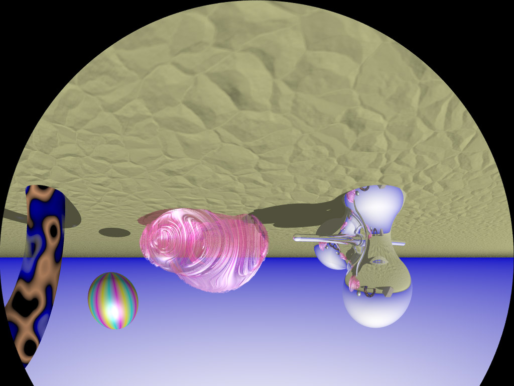
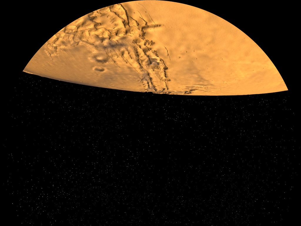
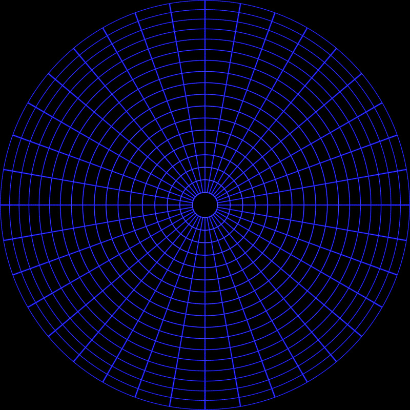
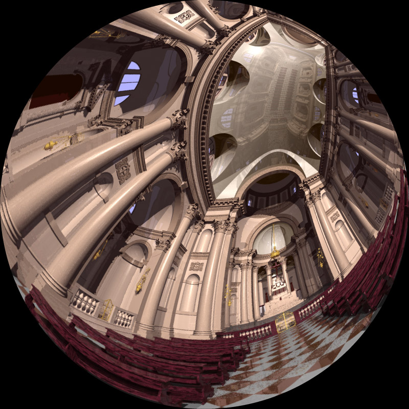
There are two main idealised fisheye projections common in computer graphics rendering, they are the hemispherical and angular fisheye. They are two from an infinite number of ways of mapping wide angle of view onto an image plane. Hemispherical fisheye A hemispherical fisheye, see figure 1, is a parallel projection of a hemisphere onto a plane, the resulting image will be circular. The widest view angle is 180 degrees (as shown) with extreme distortion at +/- 90 degrees. Because of the distortion introduced radially it is used less often than the angular fisheye distortion. Angular fisheye An angular fisheye projection is defined so that distance from the center of the image is proportional to the angle from the camera view direction. In particular, in an angular fisheye (also called f-theta lens) image the resolution is approximately equal across the whole image. An angular fisheye projection can be used for angles all the way up to a full 360 degree. A cross section of a 360 degree angular fisheye is shown in figure 2 and a 180 degree angular fisheye in figure 3. The main point to note is that the distance from the center of the image (a circle on the image plane) maps directly onto the angle around the projection sphere. A 180 degree fisheye projects half the environment onto a circular image, a 360 degree fisheye projects the whole environment onto a circular image. As an aside, while it is quite easy to get 180 degree fish eye lens and even up to 220 degrees, it is also feasible to photograph almost a 360 degree fisheye. This can be accomplished by photographing a silvered ball using a telephoto lens. Note that the images captured with real fisheye lens will have other distortions to the ideal lens described here. The image below is a 180 degree angular fish eye projection rendered using the PovRay raytracer.

Creating an angular fisheye To create an angular fisheye projection one needs to determine the vector from the camera into the scene for every point in the image plane. Figures 4 through 7 outline the procedure, at least, one possible method. First the image coordinates are transformed from pixel coordinates (i,j) into normalised coordinates (x,y) ranging from -1 to 1, figure 5. Next the radius r and angle phi to the x axis is calculated, figure 6. Note that if atan2() is supported in your maths library then that can be used as a more direct way of calculating the angle phi. At this stage any pixels where r > 1 are ignored (drawn black or some other background colour). Finally, r is mapped onto theta, phi is used directly as the polar coordinates of the direction vector from the camera into the scene. The angle theta is just r multiplied by half the intended fisheye angle which may be anything up to 360 degrees. Inverse transform One way to use fisheye projections is as environment maps. In this case one generally uses a 180 degree angular fisheye image and maps it onto a hemisphere centered at the virtual camera. The general requirement is to create the correct u,v texture coordinates for each vertex making up the polygons on a unit radius hemisphere. Most texture mapping requires u,v coordinates between 0 and 1 in each direction, the formula based upon the conventions used here is as follows for a unit vector (x,y,z). u = r cos(phi) + 0.5
v = r sin(phi) + 0.5 where r = atan2(sqrt(x*x+y*y),p.z) / pi
phi = atan2(y,x) There are many ways to create a polygonal representation of a unit hemisphere. Two examples are given below in pseudo C code. The first uses a grid in the x,y plane and calculates the z value using the equation of the sphere x2 + y2 + z2 = r2. The second creates a sphere using polar coordinates with one pole directly in front of the camera. In both cases the sphere is of unit radius and centered at the origin. Method 1 - grid Method 2 - polar Note that for the above the normal at each point is the same as the point itself. The value of N above relates to the resolution of the sphere, the higher the more polygons created. In reality one might choose more efficient methods than the above since it computes the same point multiple times (for shared vertices). For example both methods can be easily modified to support quad or triangle strips for OpenGL. The texture coordinate for any point on the sphere might be calculated as follows. Source Code Paraboloid For completeness it should be mentioned that another way to record wide angle views for environment maps is to use a paraboloid. The main advantage is that there are efficient numerical methods for unmapping the image for standard perspective views. Figure 8 shows the cross section, the formula is generally something of the form.
z = 0.5 - 0.5 (x
2 + y
2) for x
2 + y
2 <= 1
References Max, N.,
Computer Graphics Distortion for IMAX and OMNIMAX Projection.
Proc Nicograph 83, Dec 1983 pp 137. Greene, N.,
Environment Mapping and Other Applications of World Projections
IEEE Computer Graphics and Applications, November 1986, vol 6, no 11, pp 21 Wyvill, G., McNaughton, C.,
Optical Models
Computer Graphics International, 1990, Springer p88 Fleck M.,
Perspective projection: The wrong imaging model
University of Iowa, Tech Report #95-01 Svoboda, T., Pajdla, T., Hlavac, V.,
Central Panoramic Cameras: Geometry and Design
Czech Technical University, Tech Report K335/97/147. | Figure 1
 Figure 2
 Figure 3
 Figure 4
 Figure 5
 Figure 6
 Figure 7
 Figure 8
 |
Non linearily Real fisheye lenses rarely follow the precise linear relationship between radius on the fisheye image plane and latitude. The most common form of deviation is a compression of the image towards the rim of the fisheye circle. Of course if this non-linearity is a problem it can be corrected for, at the expense of some loss of resolution at the rim.

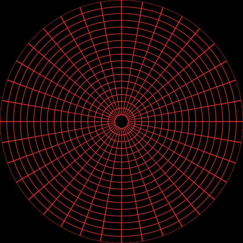
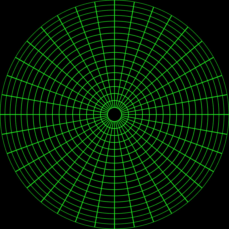
Appendix: Approximations Some raytracing packages don't support a native fisheye camera, the question is often asked "can a spherical mirror be used to create a fisheye view?". The basic idea is to render the view of the scene by pointing the virtual camera at a perfectly reflective spherical surface. The answer is "the result is close but not exactly correct". Three rendering are shown below, the scene is simply a hemisphere represented as a regular grid of lines of latitude and longitude.
| Equiangular fisheye This is the correct result rendered with a equiangular fisheye lens. Note that the spacing of the lines of latitude is constant. |
 | | Aperture: 180 degrees
Camera at the origin
Unit polar grid at origin
Lines of longitude: 10 degree steps
Lines of latitude: 5 degree steps

3D polar frame hemisphere
|
Mirror sphere, perspective projection |  | | Aperture: 60 degrees
Mirror radius: 0.001
Camera positioned for 180 degree reflection

|
Mirror sphere, orthographic projection |

| | Mirror radius: 0.001
Camera position very close to mirror radius

|
Overlap of fisheye and orthographic mirror The following is the perfect fisheye superimposed with the orthographic rendering. The biggest difference is around the mid latitudes, for example, if such a projection was used in a planetarium then objects that remain at the same distance from the camera but move from the pole to the horizon will appear to change size.

It should be noted that a mirror (not spherical) can be designed such the correct result is achieved. In the authors opinion it is vastly better to render cubic maps from which correct fisheye projections can be derived.
Offaxis fisheye projection Written by
Paul Bourke
October 2001, modified January 2004
Introduction There exist a number of full dome environments that project angular fisheye or other radial functions. If the angular fisheye is created correctly then the resulting image after projection onto the dome surface appears undistorted. Unfortunately if the projector uses a single fisheye lens then the standard fisheye projection as described here requires that both the lens and the viewer are located at the center of the dome, obviously impossible. As the viewer moves away from the center the image appears increasingly distorted. This isn't normally a problem for large planetariums where the radius of the dome is very much larger than the seating area and in any case nothing can be done since there are multiple viewers. For smaller domes the effect is more marked and the viewer can easily move significant distances from the center. It is possible to create a modified fisheye image so that if viewed from a particular position the projected image will appear undistorted, this is called an off axis fisheye image. This is the same principle employed when creating stereo pairs where one uses an off-axis (asymmetric) perspective frustum for each eye.
Algorithm
| Creating an off-axis fisheye is quite straightforward. First, create the fisheye projection world vector p as described here. The vector p' is derived as shown in the diagram on the right. The new ray p' is the ray p minus the vector to the view position. While the diagram on the right shows the view position along the y axis, it is normally applied to any point in the x,y plane as the dome viewer will most commonly move around on that plane. Note that as the viewer moves towards the rim the image gets increasingly stretched in that direction. This violates the usual characteristic of angular fisheye images where a pixel in image space is proportional to the angle in fisheye space. Or put another way, all pixels in the fisheye image are the same dimensions in the projected image, this can be seen in the example below.
Viewer at (0,0)
 | Viewer at (0.5,0.5)
 |
| | 
Figure 1
|
A common approach to creating content for dome environments is to render standard projections onto the faces of a cube. The off-axis fisheye can be computed from these at interactive rates and so a single viewer with a head tracking device can be presented with a corrected image as they walk around the base of the dome.
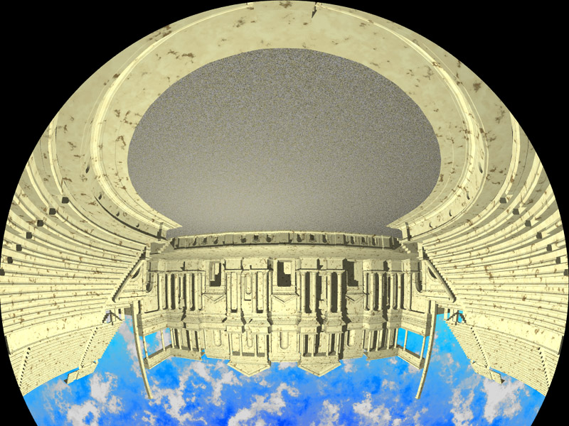
Test Pattern The following test pattern was used to test the correctness of the off-axis fisheye. It is a rendering of a cubic room, each wall is a different colour and constructed with a regular grid of bars. If the fisheye generation is correct the curved lines in the fisheye image should appear straight when projected onto the dome. The coordinate above each image is the position of the viewer.
Offset = (0,0)
 | Offset = (0,0.5)
 | Offset = (0,0.75)
 | Offset = (0,0.95)
 | Offset = (0.5,0.5)
 | Offset = (0.7,0.7)
 |
This example is rendered in PovRay onto a 5 wall cubic environment map, the off-axis fisheye is created from these 5 images. (5view.ini, 5view.pov, 5viewcamera.pov) This has the advantage of being able to create multiple offaxis fisheye images from one set of cubic environment maps, this would not be possible if the offaxis fisheye was rendered directly in PovRay (something that is easy to arrange by modifying the PovRay source code).
Creating offaxis projections from existing fisheye images Given an existing fisheye image, an offaxis fisheye can be created for any offaxis position. There is a full mapping for 180 degree fisheye images, smaller angle images result in an incomplete mapping. It reads a TGA image representing a fisheye image and creates an offaxis fisheye as another TGA file. Note that there are important resolution issues to consider, this works best when going from very high resolution fisheye images to lower resolution ones. The code here is a simple command line based UNIX utility, it supports supersampling antialiasing and variable output image size. offaxis tgafilename [options]
Options:
-a n set antialias level (Default: 1)
-w n width of the output image (Default: 500)
-h n height of the output image (Default: width)
-dx n x component of the offaxis vector (Default: 0)
-dy n y component of the offaxis vector (Default: 0)
-v debug/verbose mode (Default: off)
Original fisheye image
 | X axis offset of 0.3
 | Y axis offset of 0.3
 | X and Y axis offset of 0.3
 |
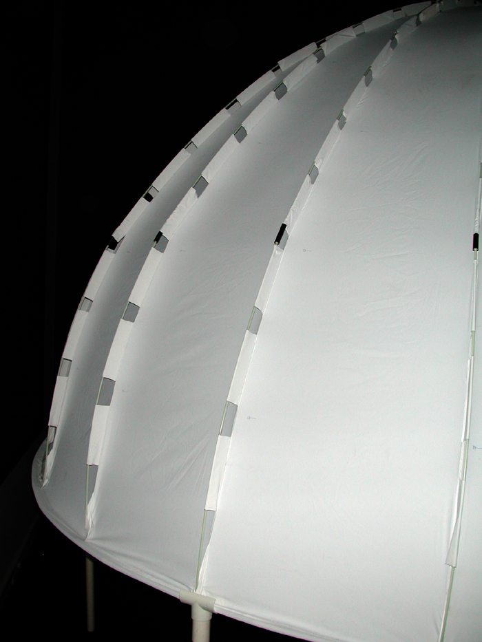
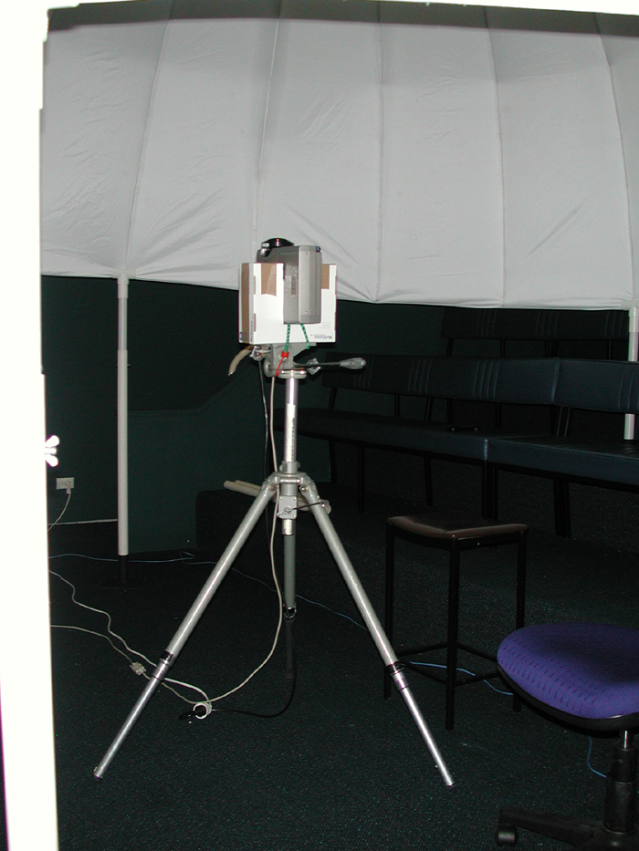
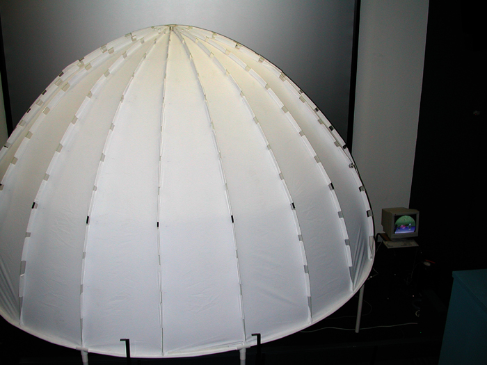
Photos of a Prototype Dome


Example Images used in the Prototype Dome


Note that for these tests an Elumens projector was used. This is a standard projector with their fisheye lens and as such the projector projects a 4:3 width to height ratio while fisheye images are 1:1. This is addressed by clipping off 25% of the image, in the case of the Elumens dome this is normally the bottom 25%. In our case we chose to clip the top 25%, this conveniently gave the viewers a position behind the projector from which to view the images without being blinded.
 | 
Figure 2
|
Addendum The offaxis correction as described above only applied to shifting the observer around on the rim plane of the hemisphere. A similar correction can be made to compensate for the observer being within the dome, or in the more likely case, away from the rim of the dome (along the negative z axis, see figure 1). This correction is applied in exactly the same way but note that it results in a reduced field of view unlike offset positions on the rim plane which result in stretching distortion but the same field of view.
网址: http://paulbourke.net/dome/fisheye/ |


 275
275


 被折叠的 条评论
为什么被折叠?
被折叠的 条评论
为什么被折叠?
 到【灌水乐园】发言


