


Table of Contents
1.5 Constraints and Assumptions 1
2 High-Level POC Architecture 2
3.1 Sequence Diagram for Iaas & SaaS 3
5.1 Server Physical Infrastructure 6
5.1.1 Server Physical Machine Table 6
5.1.6 Remote Desktop Gateway Server (IBMH1) 7
5.1.7 Remote Desktop Gateway Server (IBMH2) 8
5.2 Server Virtual Infrastructure 8
5.2.2 Active Directory Server (DC1, DC3 & DC5) 9
5.2.3 System Center Virtual Machine Manager Server (SCVMM1) 10
5.2.4 System Center Operations Manager Server (SCOM01) 10
5.2.5 System Center Self Service Portal Server (SSP-V2) 10
5.2.6 Exchange CAS/HUB Server (CH1 and CH2) 11
5.2.7 Exchange Mailbox Server (MBX1, MBX2 & MBX3) 11
5.2.8 Hyper-V Server Cluster 11
5.3 Implementation of Design 11
5.7 Security Considerations 14
5.7.1 End User Access to the solution 14
5.7.2 Host Operating System Configuration 14
6.4 iSCSI Target Host Setup 19
6.5 Build R2 Hyper-V Core hosts 27
6.16.1 Terms and Abbreviations 89
Appendix A – Hyper-V Host Server Farm Pattern 90
Appendix B – Host Cluster patterns 91
Node and File Share Majority 91
Appendix C – Network Architecture 93
Appendix D - Processor Architecture 94
Appendix E – Memory Architecture 95
Appendix G - Disk Redundancy Architecture 97
Appendix H - Fibre Channel Storage Area Network 98
Appendix I - Disk Controller or HBA Interface 99
Appendix J - Cluster Shared Volumes 100
Appendix K - System Center Virtual Machine Manager R2 2008 102
Virtual Machine Manager Server 102
Microsoft SQL Server Database 102
Delegated Management and Provisioning Web Portal 103
Appendix L – Hyper-V Overview 104
Appendix M – Hardware Architecture 105
Cluster Host Server Overview 107
-
Introduction
The GPC-POC is a self-contained virtualised management infrastructure which can be deployed in a suitable environment to show the use of Microsoft Technologies in provisioning and managing Virtual Machines. This document covers the deployment details to allow the technical personnel involved in deployment the solution to understand what components are involved and how they are configured.
The GPC-POC Deployment Guide provides the information you need to prepare for and deploy the Virtual Machine Manager Self-Service Portal (VMMSSP, or the self-service portal) in your datacenter. Before you follow the instructions in this guide.
-
About this Document
This document is for Govt. Private Cloud (GPC) and provides a deployment scenario for self-service portal component guide.
-
Intended Audience
The intended audience of this document is the technical personnel engaged in implementing the GPC solution within their own environment.
-
Document Scope
The scope of this document is concerned with Microsoft technologies only.
-
Constraints and Assumptions
The server and storage hardware required for the GPC-POC environment is as specified by the hosting partner provided it meets the minimum requirements as defined in this document.
There are also a lot of related conditions and technologies that will have an impact on the GPC-POC working. Some of those assumptions are listed in the table below:
Assumption | Explanation |
Physical environment | It is assumed that a server environment exists with enough floor space, power, air conditioning, physical security etc. |
Stable network | It is assumed that the local and wide area network infrastructure which includes physical components switches, routers, cable etc. And the logical components like routing, broadcasts, collisions etc. Are stable and under control. Having an unstable network can result in unexpected behaviour. |
Need to add more Constraints or Assumptions |
Table 1: Constraints and Assumptions
-
High-Level POC Architecture

Figure 1: High Level POC Architecture
-
POC is intended to be delivered on harddrive for installation at customer site with limited hardware investment.
-
It's only require 6-8 physical machines
-
Goal is to demonstrate IaaS & SaaS scenarios for Private Cloud deployment environment.
-
The POC uses a Windows iSCSI server instead of a SAN for portability reasons. iSCSI is a storage protocol used to connect to a network device that moves storage-related data. It allows clients to send SCSI commands to remote, consolidated storage targets (or disk arrays) in the same way the client can interact with a locally attached disk. A common misconception is that you can connect iSCSI over your existing LAN infrastructure.
-
High-Level Scenarios
High-Level Showcase Scenarios (10-15) | |
IaaS (Dynamic Datacenter) | SaaS (Exchange) |
1. New tenant (organization) sign-up | 1. New tenant (organization) sign-up |
2. New environment provisioning request | 2. New tenant services configuration |
3. Virtual machine request | 3. Tenant admin set-up |
4. Virtual machine template setting | 4. New user (mailbox) addition |
5. Virtual machine provisioning | 5. Distribution list management rights assignment |
6. Reporting | 6. Charge back reporting |
-
Sequence Diagram for Iaas & SaaS

Figure 2: Sequence Diagram for Iaas & SaaS
Following are the sequence diagram steps
-
Business Group Customer requested for Emailbox setup for the department / organization.
-
Request goes to IT Aministrator of the department / organization. IT Admin enters the New Machine request through Website Form.
-
It goes to Data Center Admin approval for VMs aqquision. Once approved, approval mail sent to IT Adminstrator.
-
IT Administrator configure and installs the Exchange on VM Servers.
-
IT Administrator Provision and Add Tenant and Mailbox for users.
-
Finally the request gets completed and mail been send to BG Customer to utilize the services.
-
Report gets generated based on the service(space, bandwidth, etc..) usage and charge back to the department based on the usage.
-
Deployment Scenarios
-
This guide steps you through the deployment process for the self-service portal. It includes the following sections:
-
Deployment Scenarios for the Self-Service Portal Components. Describes the two primary deployment scenarios.
-
Environmental Prerequisites. Specifies the prerequisites that affect resources beyond the computers that will run the self-service portal components, including security recommendations.
-
Self-Service Portal System Requirements. Lists the system requirements for the self-service portal components in each of the deployment scenarios.
-
Installing the Virtual Machine Manager Self-Service Portal. Provides the steps to install the self-service portal components in each deployment scenario.
-
Uninstalling the Self-Service Portal Components. Provides the steps to uninstall the self-service portal components in each deployment scenario.
-
Next Steps: Configuring the Self-Service Portal. Provides information about the guides and other resources to use to complete the post-deployment tasks that prepare the self-service portal for normal operation.
After you complete the procedures in this guide, continue to the Virtual Machine Manager 2008 R2 VMMSSP Datacenter Administration Guide (included in the self-service portal documentation package) for information about configuring the self-service portal and setting up services for business units. For more details please refer to the link http://www.microsoft.com/downloads/details.aspx?FamilyID=fef38539-ae5a-462b-b1c9-9a02238bb8a7&displaylang=en and download a file VMM08R2_VMMSSPDocumentation.zip for more information.
-
Solution Design
The GPC-POC is based on a self-contained domain environment consisting of a number of management servers to support a scalable Hyper-V cluster onto which the solution will provision multiple Virtual Machines:

Figure 3: Hyper-V cluster Nodes with Virtual Machine
In order to make the solution as portable as possible, the management servers are themselves provided as virtual machines. This allows them to be scaled at the virtual host level to higher levels of memory/processor and disk as required without losing any portability.
The actual GPC-POC components in the handover consist only of the virtual machines making up the management servers. The associated Hyper-V Cluster needs to be created after the management servers are in place in the environment as it will need to be joined to the GPC-POC domain.
Providing a Hyper-V Cluster as the Virtualisation platform allows for fast transfer of the virtual machine servers to a different physical server in the event of unexpected hardware failure of the host. Live Migration will be used in the event of scheduled maintenance on the host servers and will provide continuous service with no outage or service loss.
The sections below covers the detailed configuration for the GPC-POC Infrastructure Environment.
-
Server Physical Infrastructure
-
Server Physical Machine Table
-
Base OS Server Name | Assigned Machine | Bits | RAM | CPU | Disks | Virtual Switch "Public" | Virtual Switch "Hyper-V & Exchange Replication" | Purpose |
HPB1 (HPV1) | HP Blade 1 | x64 | 32 GB | Quad Core | 2 X 150 GB (300 GB) | Gigabit Ethernet External NIC1 10.1.1.x VLAN1 Corp or VPN | Gigabit Ethernet External NIC2 10.1.2.x VLAN2 Lab internal | Hyper-V (cluster) DDC (SQL, DIT-SC, SCCM, SCOM, SCVMM + Library) Exchange CAS + Hub |
HPB2 (HPV2) | HP Blade 2 | x64 | 32 GB | Quad Core | 3 X 150 GB (300 GB) | Gigabit Ethernet External NIC1 10.1.1.x VLAN1 Corp or VPN | Gigabit Ethernet External NIC2 10.1.2.x VLAN2 Lab internal | Hyper-V failover for HPV1 |
HPB3 (HPV3) | HP Blade 3 | x64 | 32 GB | Quad Core | 4 X 150 GB (300 GB) | Gigabit Ethernet External NIC1 10.1.1.x VLAN1 Corp or VPN | Gigabit Ethernet External NIC2 10.1.2.x VLAN2 Lab internal | Hyper-V (cluster) DAS (273GB - RAID5) Exchange DAG |
HPB4 (HPV4) | HP Blade 4 | x64 | 32 GB | Quad Core | 5 X 150 GB (300 GB) | Gigabit Ethernet External NIC1 10.1.1.x VLAN1 Corp or VPN | Gigabit Ethernet External NIC2 10.1.2.x VLAN2 Lab internal | Hyper-V (cluster) DAS (273GB - RAID5) Exchange DAG |
IBMH1 | IBM 3850 + 2 Fusion IO cards | x64 | 16 GB | Quad Core Intel Xeon Series 7400 | 2 X 650 GB Fusion IO | Gigabit Ethernet External NIC1 10.1.1.x VLAN1 Corp or VPN | N/A | iSCSI + Remote Desktop Gateway |
IBMH2 | IBM 3850 | x64 | 12 GB | Quad Core Intel Xeon Series 7400 |
| Gigabit Ethernet External NIC1 10.1.1.x VLAN1 Corp or VPN | N/A | Hyper-V Dual NIC gateway host for remote access May host AD+DNS if Lenovo is not available |
LENH1 | Lenovo RD210 | x64 | 8 GB |
|
| Gigabit Ethernet External NIC1 10.1.1.x VLAN1 Corp or VPN | N/A | AD+DNS |
LENH2 | Lenovo RD 210 | x64 |
|
|
|
|
| This box will not be available to GPC |
Table 2: Server Physical Machine Table
-
HPV1
Following are the services installed on HPV1 VM Server
- Hyper-V (cluster)
- DDC (SQL, DIT-SC, SCCM, SCOM, SCVMM + Library)
- Exchange CAS + Hub
-
HPV2
Following are the services installed on HPV2 VM Server. It's Hyper-V failover for HPV1
- Hyper-V (cluster)
- DDC (SQL, DIT-SC, SCCM, SCOM, SCVMM + Library)
- Exchange CAS + Hub
-
HPV3
Following are the services installed on HPV3 VM Server
- Hyper-V (cluster)
- DAS (273GB - RAID5)
- Exchange DAG
-
HPV4
Following are the services installed on HPV3 VM Server
- Hyper-V (cluster)
- DAS (273GB - RAID5)
- Exchange DAG
-
Remote Desktop Gateway Server (IBMH1)
The Remote Desktop Gateway Server provides Secure Remote Desktop access to the Virtual Machines provisioned by the end-users.
-
Access Rights – Administrators and Department Users
-
Machine Access – Note: This is set to allow access to all machines in the environment initially but can be limited as required.
Note: The Remote Desktop Gateway Server currently uses a self-signed certificate which will need to be installed into the Trusted Root store on all potential client machines in order to allow connectivity. Alternatively, this certificate can be replaced by another which already has a Trusted Root certificate installed on the end-user machines.
-
Remote Desktop Gateway Server (IBMH2)
The Remote Desktop Gateway Server provides Secure Remote Desktop access to the Virtual Machines provisioned by the end-users.
-
Access Rights – Administrators and Department Users
-
Machine Access – Note: This is set to allow access to all machines in the environment initially but can be limited as required.
Note: Hyper-V Dual NIC gateway host for remote access. May host AD+DNS if Lenovo is not available.
-
LENH1
Following are the services installed on LENH1 VM Server
- Active Directory and DNS
-
Server Virtual Infrastructure
-
Virtual Management Servers
-
The Virtualised Management Servers are pre-configured as follows and any changes to the configuration will impact on other VM Server setting:
Management Server | Machine Name | VM Network | External IP | IP Address |
Active Directory Server | DDC1-DC01 | Internal | 192.75.183.35 | 10.1.1.120 Contoso.gov |
Active Directory Server | DDC1-DC02 | Internal | 192.75.183.30 | 10.1.1.121 Contoso.gov |
Active Directory Server | DDC1-DC03 (Failover) | Internal | 192.75.183.35 | 10.1.1.122 Contoso.gov |
SCVMM SQL Server | DDC1-SCVMM01 | Internal | 192.75.183.30 | 10.1.1.180 Ops.contoso.gov |
SCOM Server | DDC1-SCOM01 | Internal | 192.75.183.30 | 10.1.1.181 Ops.contoso.gov |
Remote Desktop Gateway Server | DDC1-IBMH | Internal | 192.75.183.34 | 10.1.1.109 Contoso.gov |
Exchange Server | DDC1-MBX1 | Internal | 192.75.183.32 | 10.1.1.220 Resource.gov |
Exchange Server | DDC1-MBX2 | Internal | 192.75.183.33 | 10.1.1.221 Resource.gov |
Exchange Server | DDC1-MBX3 | Internal | 192.75.183.33 | 10.1.1.222 Resource.gov |
Table 3: VM Servers Configuration table
Note: External Network 1 corresponds to the Virtual Machine Network in the Network Architecture
-
New Virtual Machines
All new Virtual Machines will be built on the Host Cluster and be attached to External Network 1 (the Virtual Machine Network). They will also receive a DHCP address from the AD Server.
-
Active Directory Server (DC1, DC3 & DC5)
Base OS Server Name | Physical Host Machine | Bits | RAM | CPU | Disks | Virtual Switch "Public" | Virtual Switch "Hyper-V & Exchange Replication" | Purpose |
DC1 | IBMH2 | x64 | 12 GB | Quad Core Intel Xeon Series 7400 |
| Gigabit Ethernet External NIC1 10.1.1.x VLAN1 Corp or VPN | N/A | Hyper-V Dual NIC gateway host for remote access May host AD+DNS if Lenovo is not available |
DC3 | IBMH2 | x64 | 12 GB | Quad Core Intel Xeon Series 7400 |
| Gigabit Ethernet External NIC1 10.1.1.x VLAN1 Corp or VPN | N/A | Hyper-V Dual NIC gateway host for remote access May host AD+DNS if Lenovo is not available |
DC5 | IBMH2 | x64 | 12 GB | Quad Core Intel Xeon Series 7400 |
| Gigabit Ethernet External NIC1 10.1.1.x VLAN1 Corp or VPN | N/A | Hyper-V Dual NIC gateway host for remote access May host AD+DNS if Lenovo is not available |
Table 4: Virtual Machine with Active Directory
The Active Directory Server holds all the domain accounts for the management servers plus it hosts the following services required for the proper operation of the solution:
-
DNS
-
DHCP
-
Address Lease Range – 192.75.183.30-192.75.183.150
-
Scope Options:
-
Router – 192.75.183.30
-
DNS Servers – 192.75.183.34
-
DNS Domain Name – DDC1.LOCAL
-
-
-
System Center Virtual Machine Manager Server (SCVMM1)
Base OS Server Name | Assigned Machine | Bits | RAM | CPU | Disks | Virtual Switch "Public" | Virtual Switch "Hyper-V & Exchange Replication" | Purpose |
HPB1 (HPV1) | HP Blade 1 | x64 | 32 GB | Quad Core | 2 X 150 GB (300 GB) | Gigabit Ethernet External NIC1 10.1.1.x VLAN1 Corp or VPN | Gigabit Ethernet External NIC2 10.1.2.x VLAN2 Lab internal | Hyper-V (cluster) DDC (SQL, DIT-SC, SCCM, SCOM, SCVMM + Library) Exchange CAS + Hub |
HPB2 (HPV2) | HP Blade 2 | x64 | 32 GB | Quad Core | 3 X 150 GB (300 GB) | Gigabit Ethernet External NIC1 10.1.1.x VLAN1 Corp or VPN | Gigabit Ethernet External NIC2 10.1.2.x VLAN2 Lab internal | Hyper-V failover for HPV1 |
Table 5: Virtual Machine with SCVMM, Exchange & SCOM
The System Center Virtual Machine Manager is installed into the management network as a virtual machine; this instance manages the Hyper-V host servers and virtual machines. In addition, the administrator console and failover clustering toolset are installed for management of the server infrastructure. The Self-Service Portal is also implemented with role specific administration, as this functionality is used for accessing the provisioned virtual machines.
The Library holds a number of sysprepped images and hardware templates:
Name | Type | Notes |
Server 2008 R2 Ent (x64) | Template | Virtual Machine Template for Windows 2008 R2 Enterprise Edition |
Table 6: Hardware Template
-
System Center Operations Manager Server (SCOM01)
Please refer the above Table 3. The System Center Operations Manager is installed for providing a means of consolidated health monitoring across both the management servers and the provisioned virtual machines.
Additional Management Packs installed:
-
Exchange? (TBD)
-
System Center Self Service Portal Server (SSP-V2)
The Web Portal Server host the end-user interface to the GPC-POC .
Internal Web URL: http://Ops.contoso.gov/
-
Exchange CAS/HUB Server (CH1 and CH2)
The Client Access Server (CAS) role basically accepts connections from a variety of clients to allow them access to the Exchange Server infrastructure. To some extent, the CAS role has some similarities to the old front-end (FE) servers in Exchange 2010.
The Exchange 2010 Hub Transport Server role is responsible for all messaging transport inside your organization. In cases where Exchange 2010 Edge Transport Servers are deployed, the Hub Transport role hands off Internet-bound messages to the Edge Transport role for processing; it also takes inbound messages that the Edge Transport server has accepted from the Internet.
Note: CH1 is Primary and CH2 is failover server.
-
Exchange Mailbox Server (MBX1, MBX2 & MBX3)
Give users bigger and even more reliable mailboxes. With a unified solution for high availability, disaster recovery and backup, as well as vastly improved IO efficiency, larger and less expensive disks are now legitimate storage solutions. Users will have greater access to mission critical email and spend less time managing their inbox.
High availability can now be added without reinstalling servers, and now all aspects of administration are handled within Microsoft Exchange. Administrators can configure a database availability group of up to 16 mailbox servers for automatic, database-level recovery from failures. Sub 30-second failover times and the ability to switch between database copies when disks fail dramatically improve an organization's uptime. Also improving uptime is the new Online Mailbox Move feature. This feature gives users nearly continuous access to their communications even while their mailbox is being relocated.
Note: MBX1 and MBX2 are Primary and MBX3 is failover server.
-
Hyper-V Server Cluster
The virtualisation platform onto which new virtual machines are provisioned consists of a multi-node Windows Server 2008 R2 cluster leveraging a shared storage area network (SAN) array with a Node and Disk Majority cluster. Each node of the cluster runs Windows Server 2008 R2 Enterprise Edition Hyper-V. Each active node in the cluster hosts and runs the virtual machines.
In the event of a failure of one of the nodes or planned maintenance, cluster failover occurs. The virtual machine guest(s) are failed over to the remaining nodes in the site boundary. If resiliency against the failure of active nodes is desired, then the surviving nodes must be able to take on the entire load of the failing nodes. The recommended approach is to have each node be physically identical and size the load on each node so that it achieves the above rules.
-
Implementation of Design
The GPC-POC is based on a set of virtualised Management servers which provide the necessary support infrastructure for provisioning of virtual machines. Not included, but required is a Hyper-V Cluster (minimum 2-nodes) which can be managed from the included SCVMM Server. This then provides the location for new virtual machines to be provisioned onto via the web portal.
-
Private Cloud Network
The Network design has to accommodate the virtualised networking requirements for both the management server infrastructure and the provisioned virtual machines. Therefore, to simplify the portability of the solution we have chosen to implement a private IP addressing scheme for the management servers. This means that access to them is only via the host server unless specific routes are added.

Figure 4: GPC-POC Network Overview
In addition, the physical management server(s) and the host cluster must both be on the same VLAN such that the virtual SCVMM and AD Servers can manage the host cluster and new virtual machines can be provisioned to it.
-
Network Architecture
The Hyper-V servers within the environment will be connected to a number of different networks.
Each of the Cluster servers will be configured with up to 5 Networks:
-
Management Network
-
Virtual Machine Network
-
Potentially an ISCSI network (if using an ISCSI SAN)
Optional
-
Cluster Heartbeat network
-
Live Migration Network (may be shared with Cluster Heartbeat Network if needed)
The Management connection is dedicated to the host itself for network I/O and management.
Optional:
-
The Cluster heartbeat connection is used by all the cluster nodes to ascertain if all nodes within the cluster are responding and operational.
-
The Live migration network is used to failover virtual machines to alternate nodes in the cluster configuration with no loss of service to the end user.
The Virtual Machine network is dedicated to the guest virtual machines.
The ISCSI Network is used for connection to the ISCSI SAN (if used).

Figure 5: Cluster Node Network Overview
-
Storage
The Storage design can be kept as simple as possible – either a FC/ISCSI connection is needed and enough disk space to cater for the potential number of virtual machines is required for the host cluster.
-
Backup and Restore
As this is purely a , Virtual machines will not be backed up.
-
Security Considerations
-
End User Access to the solution
-
Access to the solution for end-users is via RDP Gateway Server. It is assumed that the hosting environment is deployed in a secure lab, behind an external Firewall (to the GPC-POC servers).
Note: As this is a pure solution, the security of the environment will need to be reviewed against the requirements of the environment into which it is being deployed and as such firewall rules and further security lockdown measures may be required.
-
Host Operating System Configuration
-
Keep the management operating system up to date with the latest security updates.
-
Use a separate network with a dedicated network adapter for the management operating system of the physical Hyper-V computer.
-
Secure the storage devices where you keep virtual machine resource files.
-
Harden the management operating system using the baseline security setting recommendations described in the Windows Server 2008 R2 Security Compliance Management Toolkit.
-
Configure any real-time scanning antivirus software components installed on the management operating system to exclude Hyper-V resources.
-
Do not use the management operating system to run applications.
-
Do not grant virtual machine administrators permission on the management operating system.
-
Use the security level of your virtual machines to determine the security level of your management operating system.
-
-
Deploying GPC-POC
-
Redmond Workflow
-
Build iSCSI Target host
-
Build 2008 R2 Core Hyper-v hosts
-
Create Virtual Switches with Hyper-V Manager
-
Virtual Switch Name | Type | NIC | Network | Physical Swtich | Connectivity |
Public | External | NIC1 | 10.1.1.x | VLAN1 | Corp or VPN connectivity |
Replication | External | NIC2 | 10.1.2.x | VLAN2 | Lab internal |
Hyper-V Failover Cluster | External | NIC2 | 10.0.0.x | VLAN2 | Lab internal |
Table 8: Virtual Switches
-
Connect iSCSI volume to the Hyper-V host that will be running the DC1 VM
-
Build DC1 VM (...or physical host)
-
Copy the Exported Virtual Machine contents of just DC1,
-
from external USB drive to a local folder on the Hyper-v host,
-
such as C:\GPC Lab\Exported Virtual Machines
-
(you can skip this if you want to save time...use Hyper-v Mgr to import directly from USB drive)
-
-
Hyper-v Manager import of DC1 VM from the local C: drive
-
(or if you want to save some time, from the USB drive)
-
Just make sure that the DC1 VM is imported to a local directory on the Hyper-v host
-
-
Configure contoso.gov
-
Install Failover Clustering Feature on hosts
-
User Hyper-v Manager to create virtual switch for Clustering, on all hosts
-
Use the Failover Cluster Manager MMC snap-in to
-
Create a hyper-v cluster with the physical hosts
-
Enable CSV
-
Create a CSV disk
-
Copy
-
-
Build SCVMM & SQL VM
-
iSCSI Initiator
-
Connect to E: drive
-
Install SQL
-
Install SCVMM
-
Create another CSV disk for the SCVMM Library
-
***due to a storage issue, we were not able to get all the ISO images copied to the external USB drive, so you will need to copy them to this CSV disk
-
Create Exchange Template
-
Create CAS/HT Template
-
Create DC Template
-
Create Client Templates
-
-
Use SCVMM or Hyper-v Manager to import remaining VMs onto the appropriate hosts
-
Spread the 3 MBX VMs across the HPV hosts, and DO NOT enable Live Migration for these VMs
-
Spread the remaining VMs across the HPV hosts with Live Migration enabled
-
-
Customer Workflow
Base OS Server Name | Assigned Machine | Bits | RAM | CPU | Disks | Virtual Switch "Public" | Virtual Switch "Hyper-V & Exchange Replication" | Availability Date | Purpose |
HPB1 | HP Blade 1 | x64 | 32 GB | Quad Core | 2 X 150 GB (300 GB) | Gigabit Ethernet External NIC1 10.1.1.x VLAN1 Corp or VPN | Gigabit Ethernet External NIC2 10.1.2.x VLAN2 Lab internal | Now | Hyper-V (cluster) DDC (SQL, DIT-SC, SCCM, SCOM, SCVMM + Library) Exchange CAS + Hub |
HPB2 | HP Blade 2 | x64 | 32 GB | Quad Core | 3 X 150 GB (300 GB) | Gigabit Ethernet External NIC1 10.1.1.x VLAN1 Corp or VPN | Gigabit Ethernet External NIC2 10.1.2.x VLAN2 Lab internal | Now | Hyper-V failover for HPV1 |
HPB3 | HP Blade 3 | x64 | 32 GB | Quad Core | 4 X 150 GB (300 GB) | Gigabit Ethernet External NIC1 10.1.1.x VLAN1 Corp or VPN | Gigabit Ethernet External NIC2 10.1.2.x VLAN2 Lab internal | Now | Hyper-V (cluster) DAS (273GB - RAID5) Exchange DAG |
HPB4 | HP Blade 4 | x64 | 32 GB | Quad Core | 5 X 150 GB (300 GB) | Gigabit Ethernet External NIC1 10.1.1.x VLAN1 Corp or VPN | Gigabit Ethernet External NIC2 10.1.2.x VLAN2 Lab internal | Now | Hyper-V (cluster) DAS (273GB - RAID5) Exchange DAG |
IBMH1 | IBM 3850 + 2 Fusion IO cards | x64 | 16 GB | Quad Core Intel Xeon Series 7400 | 2 X 650 GB Fusion IO | Gigabit Ethernet External NIC1 10.1.1.x VLAN1 Corp or VPN | N/A | June 16 for Fusion IO cards | iSCSI |
IBMH2 | IBM 3850 | x64 | 12 GB | Quad Core Intel Xeon Series 7400 |
| Gigabit Ethernet External NIC1 10.1.1.x VLAN1 Corp or VPN | N/A | Now | Hyper-V Dual NIC gateway host for remote access May host AD+DNS if Lenovo is not available |
LENH1 | Lenovo RD210 | x64 | 8 GB |
|
| Gigabit Ethernet External NIC1 10.1.1.x VLAN1 Corp or VPN | N/A | June 16 or later | AD+DNS |
LENH2 | Lenovo RD 210 | x64 |
|
|
|
|
| N/A | This box will not be available to GPC |
Table 9: Hardware Configuration
-
Passwords
Domain | User Account | Password |
Scvmm-sql-1 | Local Administrator | 1DDCgpclab |
Dc1 | Domain Administrator | 1GPClab |
| Domain Labadmin | 1GPCcontoso |
Hpv5 | Local Administrator | 1GPCcontoso |
Sccm-scom1 | Local Administrator | 1GPCcontoso |
DC3 | OPS Administrator | 1GPClab 1GPCcontoso |
CAS1 |
|
|
DDC-Jump 192.168.0.100 | OPS Administrator | 1GPCcontoso |
DDC-AD1 192.168.0.110 | CONTOSO labadmin | 1Csltgap |
Domain | User Account | Password |
CONTOSO | Clusteradmin | 1GPCcontoso |
Table 10: Passwords
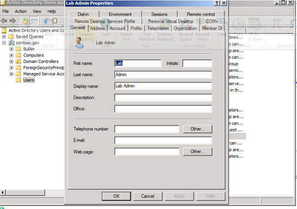
Figure 6: Lab Admin Properties


Figure 7: Administator Properties
-
iSCSI Target Host Setup
-
Install iSCSI target software on designated host

Figure 8: iSCSI Software Setup-1

Figure 9: iSCSI Software Setup-2
-
Right click on iSCSI Target and select "Create an iSCSI Target"

Figure 10: iSCSI Software Setup-3

Figure 11: iSCSI Software Setup-4
-
Get the IQN of the Hyper-v host that will initially build the contents of the iSCSI volume, which will later be used for the Cluster Shared Volume

Figure 12: iSCSI Software Setup-5
-
On the iSCSI Target Host, paste the IQN identifier of the Hyper-v hosts that we will use to offload the contents of the external USB drive

Figure 13: iSCSI Software Setup-6

Figure 14: iSCSI Software Setup-7
-
Create virtual disk for iSCSI target, Right click on gpc-storage or select from Actions pane on the right and Select "Create Virtual Disk for iSCSI Target"

Figure 15: iSCSI Software Setup-8
-
Or you can select "Devices", Right click, and select "Create Virtual Disk"

Figure 16: iSCSI Software Setup-9

Figure 17: iSCSI Software Setup-10

Figure 18: iSCSI Software Setup-11
-
This is a 1GB quorum disk for clustering

Figure 19: iSCSI Software Setup-12

Figure 20: iSCSI Software Setup-13
-
Build R2 Hyper-V Core hosts

Figure 21: Build R2 Hyper-V Core hosts - 1
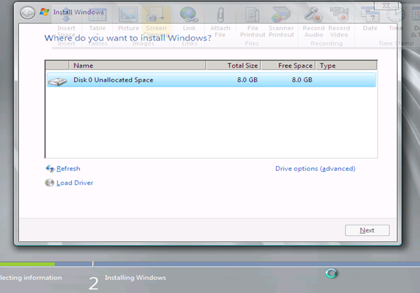
Figure 22: Build R2 Hyper-V Core hosts - 2

Figure 23: Build R2 Hyper-V Core hosts - 3
-
iSCSI Client Setup

Figure 24: iSCSI Client Setup - 1

Figure 25: iSCSI Client Setup - 2
-
Copy the IQN of the client VM or host, which will be pasted into the iSCSI Target host configuration

Figure 26: iSCSI Client Setup - 3
-
Log into the iSCSI target host

Figure 27: iSCSI Client Setup - 4
-
Go to the "Advanced" tab, and paste in the IQN of the Client VM or host

Figure 28: iSCSI Client Setup - 5
-
Go back to the client and run the iSCSI Initiator program again

Figure 28: iSCSI Client Setup – 5
-
Type in the IP address or FQDN of the iSCSI Target host, and click "Quick Connect"

Figure 29: iSCSI Client Setup - 6
-
You should see this:

Figure 30: iSCSI Client Setup - 7
-
Use the Server Manager tool to navigate to Storage/Disk Management. Find the volume and bring it online, You should see the volume (E: in this case) in the Computer window
-
Build DC VMs
-
Follow the Hyperv manager steps below to build the DC1 VM

Figure 31: Build DC VMs - 1

Figure 32: Build DC VMs - 2

Figure 33: Build DC VMs - 3

Figure 34: Build DC VMs - 4

Figure 35: Build DC VMs - 5

Figure 36: Build DC VMs - 6

Figure 37: Build DC VMs - 7
-
Install Windows Server 2008 R2 Datacenter Edition on all Virtual Machines for this PoC
-
Failover Clustering
-
http://technet.microsoft.com/en-us/library/cc732181(WS.10).aspx#BKMK_Install
-
Starting with HPV5

Figure 38: Failover Clustering- 1
-
Notice Features Summary does not have Failover Clustering

Figure 39: Failover Clustering- 2

Figure 40: Failover Clustering- 3
-
Starting the cluster configuration with HPV3, First need to create a virtual network switch with External connectivity to the 10.0.0.x network

Figure 41: Failover Clustering- 4

Figure 42: Failover Clustering- 5

Figure 43: Failover Clustering- 6

Figure 44: Failover Clustering- 7
-
Build SCVMM & SQL VM
Recommended: 4 GB RAM, 2 cores, 40 GB HDD
http://technet.microsoft.com/en-us/library/cc764289.aspx

Figure 45: Build SCVMM & SQL VM- 1
System Requirements: Installing VMM on a Single Computer
http://technet.microsoft.com/en-us/library/cc764289.aspx

Figure 46: Build SCVMM & SQL VM- 2

Figure 47: Build SCVMM & SQL VM- 3

Figure 48: Build SCVMM & SQL VM- 4

Figure 49: Build SCVMM & SQL VM- 5

Figure 50: Build SCVMM & SQL VM- 6

Figure 51: Build SCVMM & SQL VM- 7

Figure 52: Build SCVMM & SQL VM- 8

Figure 53: Build SCVMM & SQL VM- 9

Figure 54: Build SCVMM & SQL VM- 10

Figure 55: Build SCVMM & SQL VM- 11

Figure 56: Build SCVMM & SQL VM- 12

Figure 57: Build SCVMM & SQL VM- 13

Figure 58: Build SCVMM & SQL VM- 14

Figure 59: Build SCVMM & SQL VM- 15

Figure 60: Build SCVMM & SQL VM- 16

Figure 61: Build SCVMM & SQL VM- 17
-
SQL 2008 Install
http://technet.microsoft.com/en-us/library/bb500469(SQL.100).aspx
http://technet.microsoft.com/en-us/library/ms143506(SQL.100).aspx
Installed SQL 2008 Enterprise:
- Copy all of the SQL Server 2008 Enterprise bits from \\products ( you can get it from MSDN as well)
-
You will need to install .Net Framework 3.5 via Role Manager prior to installing SQL:

Figure 62: SQL 2008 Install – 1

Figure 63: SQL 2008 Install – 2

Figure 64: SQL 2008 Install – 3

Figure 65: SQL 2008 Install – 4

Figure 66: SQL 2008 Install – 5
- Might as well install the "Web Server (IIS) Support", since it will be needed for the other management tools:

Figure 67: SQL 2008 Install – 6

Figure 68: SQL 2008 Install – 7

Figure 69: SQL 2008 Install – 8

Figure 70: SQL 2008 Install – 9

Figure 71: SQL 2008 Install – 10

Figure 72: SQL 2008 Install – 11

Figure 73: SQL 2008 Install – 12
- Run the SQL setup:

Figure 74: SQL 2008 Install – 13
- It may take a couple of minutes, but you will eventually get the SQL install wizard:
- Click on "Installation"
- Click on "New SQL Server stand-alone installation or add features to an existing installation"

Figure 75: SQL 2008 Install – 14

Figure 76: SQL 2008 Install – 15

Figure 77: SQL 2008 Install – 16

Figure 78: SQL 2008 Install – 17

Figure 79: SQL 2008 Install – 18

Figure 80: SQL 2008 Install – 19

Figure 81: SQL 2008 Install – 20
-
SCVMM Install
- Log into the SCVMM-SQL-1 virtual machine as:
ops\labadmin
1GPCcontoso
- Software has been copied to the local harddrive
Local Disk (C:) \GPC Lab\Virtual Machine Manager 2008 R2
- Run setup.exe
- Install VMM Server first...

Figure 82: SCVMM Install – 1

Figure 83: SCVMM Install – 2

Figure 84: SCVMM Install – 3

Figure 85: SCVMM Install – 4

Figure 86: SCVMM Install – 5

Figure 87: SCVMM Install – 6

Figure 88: SCVMM Install – 7

Figure 89: SCVMM Install – 8

Figure 90: SCVMM Install – 9
Install VMM Administrator Console…..

Figure 91: SCVMM Install – 10

Figure 92: SCVMM Install – 11

Figure 93: SCVMM Install – 12

Figure 94: SCVMM Install – 13

Figure 95: SCVMM Install – 14

Figure 96: SCVMM Install – 15

Figure 97: SCVMM Install – 16

Figure 98: SCVMM Install – 17

Figure 99: SCVMM Install – 18

Figure 100: SCVMM Install – 19

Figure 101: SCVMM Install – 20

Figure 102: SCVMM Install – 21

Figure 103: SCVMM Install – 22
Enter E:\GPC Virtual Machines for the default path and Enter the remaining defaults for adding the host

Figure 104: SCVMM Install – 23
-
DIT-SC Install
Shopping List: | VM/host | RAM | Disk | OS | Software/Roles/Features |
| 1VM | 4GB | 50GB | Server 2008 R2 | VMM 2008 R2 Admin Console |
|
|
|
|
| SQL Server 2008 Enterprise x64 |
|
|
|
|
| IIS 7.0 (windows web server role) |
|
|
|
|
| ASP .NET 2.0 |
|
|
|
|
| .NET Framework 3.5 SP1 |
|
|
|
|
| IIS v6.0 Compatibility Mode |
|
|
|
|
| Windows Authentication (NTLM or Kerberos) TURN OFF Anonymous authentication |
|
|
|
|
| Use Domain Account as service account for server component |
|
|
|
|
| Message Queuing (MSMQ) |
Table 11: DIT-SC Configuration
-
Build Win7 Client

Figure 105: Build Win7 Client – 1
-
Exchange Deployment
Virtual Machine Host Configuration - Redmond
A single forest (exchange.gov) has been created, and all the 2 CAS/HT & 3 MBX VMs have been put in that domain. You can access them, by RDP over our corp network into 10.197.215.143 as DDC-JUMP\Administrator. The password is 1GPCcontoso, which is the password for everything in the lab. The desktop for the local Admin user has RDP session saved for each CH1,2 and MBX1,2,3 VMs. You can login either local admin or exchange domain admin.
Some additional information for Exchange install:
Servers | IP Configuration |
Exchange forest DC: | DC5 (10.1.1.124) |
Primary DNS Server: | 10.1.1.124 |
Secondary DNS Server: | 10.1.1.122 |
MBX Replication IPs: | MBX1 10.1.2.220 MBX2 10.1.2.221 MBX3 10.1.2.222 |
DAG | DAG1 10.1.1.201 |
Table 12: Exchange Servers Configuration

Figure 106: Virtual Machine Host Configuration - Redmond
Virtual Machine Host Configuration - GPC

Figure 107: Virtual Machine Host Configuration - GPC
Exchange Configuration
Machine Names and associated IP addresses (all machines listed here are virtual unless otherwise noted):
-
Parent Domain
-
DC1.Contoso.Gov (physical machine)
-
10.1.1.120
-
Primary DNS for all servers
-
-
DC2.Contoso.Gov
-
10.1.1.121
-
Secondary DNS for all servers
-
-
-
Exchange Domain
-
DC3.OPS.Contoso.Gov
-
10.1.1.122
-
-
DC4.OPS.Contoso.Gov
-
10.1.1.123
-
-
CH1.OPS.Contoso.Gov
-
10.1.1.210
-
-
CH2.OPS.Contoso.Gov
-
10.1.1.211
-
-
MBX1.OPS.Contoso.Gov
-
10.1.1.220
-
10.1.2.220 (Replication Network)
-
-
MBX2.OPS.Contoso.Gov
-
10.1.1.221
-
10.1.2.221 (Replication Network)
-
-
MBX3.OPS.Contoso.Gov
-
10.1.1.222
-
10.1.2.222 (Replication Network)
-
-
Other Names
-
Exchange Domain
-
NLB1.OPS.Contoso.Gov
-
10.1.1.200
-
-
DAG1.OPS.Contoso.Gov
-
10.1.1.201
-
-
Known Issues with Exchange 2010 SP1 DF7.5 build
Scenario: • Installed Partner Hosted Exchange on Windows Server 2008 R2 • Unable to navigate to OWA (eg. https://localhost/owa) Error:
Workaround: 1. Open "IIS Manager" in the box 2. Expand "Sites" node in IIS Manager 3. Select "Default Web Site" under Sites 4. Select "ISAPI Filters" in Default Web Site
5. Remove "Microsoft.Exchange.AuthModuleFilter ISAPI Filter"
Then you should be able to access OWA now.
| |
AD and DoMT should be deployed on separate boxes\If Isolated GAL is enabled, OAB should be deleted | To use Open Domain feature where GAL is hidden to user • AD and CAS should be deployed on separate boxes • Create a tenant (e.g. myOrg) without the following features in service plan o <AddressListsEnabled>true</AddressListsEnabled> o <OfflineAddressBookEnabled>true</OfflineAddressBookEnabled> Use the following to hide GAL o Get-GlobalAddressList -Organization myOrg | Set-GlobalAddressList -IsolationMode $true Password change through OWA doesn't does not work after first logon unless "Group Policy" is changed • Start > Administrative Tools > Group Policy Management > Forest > Domains > Group Policy Objects > Default Domain Policy > Right click to "Edit" and change the "Minimum password age" to 0 to allow immediate password change.
Default connectors should be created for mail delivery between tenants • New-SendConnector –Name Test –AddressSpaces * -Smarthosts localhost -DnsRoutingEnabled $false • Get-ReceiveConnector -Identity "<NetBiosName>\Default <NetBiosName>" | Set-ReceiveConnector -PermissionGroups "ExchangeUsers, ExchangeServers, ExchangeLegacyServers, AnonymousUsers"
|
We have 2 reports that hosting command lets are not available despite the fact that the /hosting switch is used for deployment. While the Exchange Team is looking into the issue and how to fix it here is a workaround for the problem. Unfortunately it means if you ran into this issue you will have to redeploy Exchange as there is no easy way to retrofit the missing settings. 1. Build a new Lab without Exchange AD preparation run 2. install the first Exchange Role with the following commandline "setup /mode:install /roles:ca,HT /hosting /on:<ExchangeOrganizationName>", replace <ExchangeOrganizationName> with the name for the intended Exchange Organization When you check the ExchangeSetup Log under the Install-ExchangeOrganization task you should see –IsPartnerHosted $true. [02/27/2010 01:31:24.0103] [0] Setup will run the task 'Install-ExchangeOrganization' [02/27/2010 01:31:24.0103] [1] Setup launched task 'Install-ExchangeOrganization -IsPartnerHosted $true
Should you see this or any related issue in your deployment please report it to the DL. |
Pasted from <https://ea.microsoft.com/hosters/Lists/Known%20Issues%20with%20DF75/AllItems.aspx>
Installation / Configuration Steps
-
Software Required
Windows 2008 R2 (forest / domain functional level)
Create a user object svc-certauth and make a member of IIS_IUSRS group
Windows 2008 Roles
Active Directory Domain Services
Active Directory Certificate Services
Certification Authority
Certification Authority Web Enrollment
Online Responder
Certificate Enrollment Web Service
Certificate Enrollment Policy Web Service
Enterprise CA
DNS Server
Create the following DNS records
autodiscover.contoso.gov
mail.contoso.gov
casarray01.contoso.gov
dag01.contoso.gov
Windows Update after the installation of Prereqs
Additional hotfixes:
WCF Update
http://go.microsoft.com/fwlink/?LinkId=183148
Hotfix KB981002
https://connect.microsoft.com/VisualStudio/Downloads/DownloadDetails.aspx?DownloadID=27127
Hotfix KB979099 (Update for AD RMS)
http://support.microsoft.com/?kbid=979099
Microsoft Filter Pack
Install and Configure Exchange 2010 SP1 Hosting Edition
-
Build a new Lab without Exchange AD preparation (Windows 2008 R2 dc's and OS)
Domain Functional Level | Windows 2008 |
Forest Functional Level | Windows 2008 |
Exchange Member Servers OS | Windows 2008 R2 |
-
Install the first Exchange Role with the following commandline
"setup /mode:install /roles:ca,HT /hosting /on:<ExchangeOrganizationName>"
When you check the ExchangeSetup Log under the Install-ExchangeOrganization task you should see –IsPartnerHosted $true.
[02/27/2010 01:31:24.0103] [0] Setup will run the task 'Install-ExchangeOrganization'
[02/27/2010 01:31:24.0103] [1] Setup launched task 'Install-ExchangeOrganization -IsPartnerHosted $true
Pasted from <https://ea.microsoft.com/hosters/Lists/Known%20Issues%20with%20DF75/AllItems.aspx>
Create a new Client Access Array
New-ClientAccessArray -FQDN casarray01.contoso.com -Name "casarray01.contoso.com" -Site "Toronto"
Create a certificate request
New-ExchangeCertificate -GenerateRequest -SubjectName "c=US, o=Contoso, cn=mail.contoso.gov" -DomainName cdautodiscover.contoso.gov, ecp.contoso.gov, mail.contoso.gov -PrivateKeyExportable $true
Get the thumbprint and enable the new cert with Get-ExchangeCertificate and Enable-ExchangeCertificate
Enable-ExchangeCertificate -Thumbprint 5867672A5F29B388C235E1235 -Services "IMAP, POP, IIS, SMTP"
Create a new Database Availability Group
New-DatabaseAvailablityGroup
Add mailbox servers to the DAG
Add-DatabaseAvailabilityGroupServer -Identity DAG01 -MailboxServer MBX1
Add-DatabaseAvailabilityGroupServer -Identity DAG01 -MailboxServer MBX2
Add-DatabaseAvailabilityGroupServer -Identity DAG01 -MailboxServer MBX3
Rename the default mailbox databases
Set-MailboxDatabase -Identity "Mailbox Database 0483463198" -Name MDB01
Set-MailboxDatabase -Identity "Mailbox Database 1593765178" -Name MDB02
Set-MailboxDatabase -Identity "Mailbox Database 2142150893" -Name MDB03
Add mailbox database copies
Add-MailboxDatabaseCopy -Identity MDB01 -MailboxServer MBX2
Add-MailboxDatabaseCopy -Identity MDB01 -MailboxServer MBX3
Add-MailboxDatabaseCopy -Identity MDB02 -MailboxServer MBX1
Add-MailboxDatabaseCopy -Identity MDB02 -MailboxServer MBX3
Add-MailboxDatabaseCopy -Identity MDB03 -MailboxServer MBX1
Add-MailboxDatabaseCopy -Identity MDB03 -MailboxServer MBX2
Configure the RPC Client Access Array
Set-MailboxDatabase -Identity MDB01 -RpcClientAccessServer casarray01.contoso.com
Set-MailboxDatabase -Identity MDB02 -RpcClientAccessServer casarray01.contoso.com
Set-MailboxDatabase -Identity MDB03 -RpcClientAccessServer casarray01.contoso.com
Configuring Hosted Exchange
-
Capture all steps with start-transcript in PowerShell
-
Snapshot the VMs (Domain Controllers and Exchange Servers)
-
Create Service Plans (copy existing service plan files to new names with descriptions)
-
C:\Program Files\Microsoft\Exchange Server\V14\ClientAccess\ServicePlans
-
Copy the HostingAllFeatures_Sample.servicePlan to Police.servicePlan
-
Copy the HostingBusinessMAPI_Sample.servicePlan to Tourism.servicePlan
-
-
-
Edit the mailbox plans (if req'd) for each service plan
-
Edit the serviceplan files created above, MailboxPlan section is near the bo
-
-
Add service plans to the service plan map
-
Edit the ServicePlanHostingRemap.csv and add entries for Police and Tourism
-
Tourism,5,Tourism
-
Police,6,Police
-
-
-
Create Tenant Organizations
New-Organization -Name "police.ontoso.gov" -DomainName "police.contoso.gov" -Location "en-us" -ProgramId "Tourism" -OfferId "5"
New-Organization -Name "police.ontoso.gov" -DomainName "police.contoso.gov" -Location "en-us" -ProgramId "Police" -OfferId "6"
-
Create users
New-Mailbox -name "Pamela Erling" -alias "pamela" -Organization "police.contoso.gov" -UserPrincipalName pamela@police.contoso.gov
New-Mailbox -name "Patty Fisher" -alias "patty" -Organization "police.contoso.gov" -UserPrincipalName patty@police.contoso.gov
New-Mailbox -name "Tom Gregory" -alias "tom" -Organization "tourism.contoso.gov" -UserPrincipalName tom@tourism.contoso.gov
New-Mailbox -name "Ted Johnson" -alias "ted" -Organization "tourism.contoso.gov" -UserPrincipalName ted@tourism.contoso.gov
-
Check differences with Get-Mailbox
get-mailbox -organization police.contoso.gov
get-mailbox -organization tourism.contoso.gov
-
Logon to OWA
-
Known Issues
-
No limitations on the number of VMs that a user can request. Potential future enhancement.
-
Cannot remote control a Linux machine currently (as there is no RDP connectivity). Potential to implement a telnet/X-Windows session instead in the future.
-
No automatic SCOM agent install for provisioned Linux machines. Potential future enhancement to include the agent in the source.
All Virtual machines are provisioned on same network and as such users can see all other machines on the network (but do not have logon access). Potential future enhancement to build VMs into separate VLANs but needs consideration of management infrastructure.
-
Document Information
-
Terms and Abbreviations
-
Abbreviation | Definition |
SCVMM | System Center Virtual Machine Manager |
SCOM | System Center Operations Manager |
VMM | Virtual Machine Manager |
WAN | Wide Area Network |
SAN | Storage Area Network |
SAS | Serial Attached SCSI |
VHD | Virtual Hard disk |
VSV | Virtual save state file |
VSS | Volume shadow Copy Service |
Table 8: Terms and Abbreviations
Appendix A – Hyper-V Host Server Farm Pattern
The Host Server Farm architecture pattern is illustrated below.
The architecture consists of a multi-node Windows Server 2008 R2 cluster leveraging a shared storage system such as an iSCSI or Fibre Channel storage area network (SAN) and storage array. Each node of the cluster runs Windows Server 2008 R2 with Hyper-V.
-
This pattern provides server consolidation and high availability on a greater scale.
-
Supports up to 16 nodes in a single cluster configuration.
-
Virtual machines can run on any node of the cluster.
-
In the event of a node failure, the virtual machines will be restarted automatically on any node that has the available capacity to host the failed resources.

Figure i: Hyper-V Server Farm pattern
Information
The Host Server Farm pattern provides high availability as well as better use of hardware since a single physical host can serve a passive node for up to 15 active nodes.
Appendix B – Host Cluster patterns
-
No Majority – Disk Only
The cluster has quorum if one node is available and in communication with a specific disk in the cluster storage. Only the nodes that are also in communication with that disk can join the cluster.
Microsoft Recommendations
This pattern is not recommended for High Availability as the disk can be a single point of failure.
-
Node Majority
Node Majority is a quorum model where each node that is available and in communication can vote. The cluster functions only with a majority of the votes, that is, more than half.
Microsoft Recommendations
This pattern is recommended in Failover Cluster deployments containing an odd number of nodes.
-
Node and Disk Majority
Node and Disk Majority is a quorum model in Windows Server 2008 R2 Failover Clustering. In this quorum model, a cluster remains active until half of the nodes and its witness disk is available. In case, the witness disk is offline, a cluster requires a majority of nodes to be up and running in order to successfully run the cluster. This model contains two or more nodes connected to a shared storage device. The witness disk is stored on the cluster disk. This quorum model is used in scenarios where all nodes are connected to a shared storage device on the same network.
Microsoft Recommendations
This pattern is recommended in Failover Cluster deployments containing an even number of nodes.
-
Node and File Share Majority
The file share witness feature is an improvement to the current Majority Node Set (MNS) quorum model. This feature lets you use a file share that is external to the cluster as an additional "vote" to determine the status of the cluster.
Microsoft Recommendations
This pattern is recommended in Failover Cluster deployments containing an even number of nodes and for Multi-Site failover clusters.

Figure ii: Host Cluster Patterns
Appendix C – Network Architecture
The network architecture of the host server is a frequently overlooked topic in host server sizing because Gigabit Ethernet NICs are now very inexpensive and most servers have at least two built in. The topic is important, however, because it is directly impacted by the host server architecture pattern selected. If one of the two host server cluster patterns is selected, a dedicated NIC per server is required for the cluster private (heartbeat) network. Gigabit Ethernet is a high-speed network transport, though a host server with a large number of guests may require greater than Gigabit speed, thus requiring additional NICs. Finally, it is recommended that each host server have a NIC dedicated to the host itself for network I/O and management.
A fairly large number of NICs per host server may be required. Recently, 10-Gigabit Ethernet has become commonly available and is starting to drift lower in price, similar to the way Gigabit Ethernet has done over the years. The ability for servers to utilize 10-Gigabit Ethernet NICs is a significant factor in increasing the consolidation ratio.
Microsoft Recommendations
Use multiple NICs and multi-port NICs on each host server.
-
One NIC dedicated to the host machine only for management purposes
-
One NIC dedicated to the private Cluster Heartbeat network
-
One NIC dedicated to the Live Migration network
-
One or more NICs dedicated to the guest virtual machines (use 10 gpbs NICS for highest consolidation)
-
Two or more NICs dedicated to iSCSI with MPIO
Dedicate at least one NIC/Port on each host server for guest virtual machine network I/O. For maximum consolidation ratio, utilize one or more 10-Gigabit Ethernet NICs to virtual machine network I/O.
Warning
Microsoft does not support the use of NIC teaming software. Support for these third-party technologies must be provided by the vendor.
Appendix D - Processor Architecture
Windows Server 2008 R2 with Hyper-V requires x64 processor architecture from Intel or AMD, as well as support for hardware execute disable and hardware virtualization such as Intel VT or AMD-V.
Both Intel and AMD provide a wide range of processors that are appropriate for host servers. The industry competition between the two is very tight and at any one time; one may have a performance advantage over the other. Regardless of which manufacturer is chosen, several performance characteristics are important.
The number of processor cores is a key performance characteristic. Windows Server 2008 R2 with Hyper-V makes excellent use of multi-core processors, so the more cores the better. Another important characteristic is the processor clock speed, which is the speed at which all cores in the processor will operate. It's important because it will be the clock speed of all of the guest virtual machines. This is a key variable in the consolidation ratio because it impacts the amount of candidates that the host server can handle and the speed at which those guests will operate. As an example, choosing 2 GHz processor rather than a 3 GHz processor on a server that will host 20 guests means that all of those guests will run only at 2 GHz.
At a lower level of detail, the server processor architectures make design choices in terms of the type and quantity of processor cache, memory controller architecture, and bus/transport architecture. A detailed analysis of these factors is beyond the scope of this document.
Microsoft Recommendations
x64 processor architectures are required for all Hyper-V host server architecture patterns. If you are purchasing new servers, we recommend working with your server vendor to ensure that the selected hardware is capable of running Windows Server 2008 R2 and Hyper-V, and that it is validated for Windows Server 2008 R2 failover clustering. For new servers, we recommend selecting the maximum number of cores per processor available and choosing the fastest or second fastest clock speed available.
Appendix E – Memory Architecture
Once the system architecture and processor architecture choices are made, there are relatively few options remaining for memory architecture because it is usually predetermined by the manufacturer/system/processor combination. The memory architecture choices that remain are typically quantity, speed, and latency. For Hyper-V, the most important memory architecture choice is the quantity of RAM. Most consolidated workloads (that is, individual guest virtual machines) will require at least 512 MB to 1 GB of RAM or more. Since most commodity four-socket servers can only cost effectively support between 32 and 128 GB of RAM, this is frequently the limiting factor in host server capacity.
The quantity of RAM is a more important factor than RAM speed or latency. Once the maximum amount of RAM that is cost effective is determined, if there is a remaining choice between speed and latency, choosing the memory with lower latency is recommended.
Microsoft Recommendations
Given the system and processor architectures already selected, we recommend utilizing the maximum amount of RAM that can be cost effectively added to the host system. Typically, there is a price point where the cost of moving to the next DIMM size (that is, 2 GB DIMMs to 4 GB DIMMs) is more than twice the cost, and in some cases, it approaches the cost of an entire server. We recommend fully populating the server up to that price point. For example, if the server has 8 DIMM slots and 4 GB DIMMs are much more than twice the cost of 2 GB DIMMs, we recommend fully populating the server with 2 GB DIMMs and considering a second host server if additional capacity is required.
For all host server architecture patterns, we recommend a minimum of 16 GB of RAM.
For Multi-Node Host Server Farm patterns, we recommend a minimum of 64 GB per server.
Appendix F - Drive types
The type of hard drive utilized in the host server or the storage array the host servers will have a significant impact on the overall storage architecture performance. The critical performance factors for hard disks are the interface architecture (for example, U320 SCSI, SAS, SATA), the rotational speed of the drive (7200, 10k, 15k RPM), and the average latency in milliseconds. Additional factors, such as the cache on the drive, and support for advanced features, such as Native Command Queuing (NCQ), can improve performance. As with the storage connectivity, high IOPS and low latency are more critical than maximum sustained throughput when it comes to host server sizing and guest performance. When selecting drives, this translates into selecting those with the highest rotational speed and lowest latency possible. Utilizing 15k RPM drives over 10k RPM drives can result in up to 35% more IOPS per drive.
SCSI
SCSI drives are rapidly being replaced by SATA, SAS, and Fibre Channel drives. SCSI drives are not recommended for new host server architectures; however, existing servers with U320 SCSI drives can provide excellent performance characteristics.
SATA
SATA drives are a low cost and relatively high performance option for storage. SATA drives are available primarily in the 1.5 GB/s and 3.0 GB/s standards (SATA I and SATA II) with a rotational speed of 7200 RPM and average latency of around 4 ms. There are a few SATA I drives that operate at 10k RPM and average latency of 2 ms that can provide an excellent low cost storage solution.
SAS
SAS drives are typically much more expensive than SATA drives but can provide significantly higher performance in both throughput, and more importantly, low latency. SAS drives typically have a rotational speed of 10k or 15k RPM with an average latency of 2 to 3 ms.
Fibre Channel
Fibre Channel drives are usually the most expensive and typically have similar performance characteristics to SAS drives but use a different interface. The choice of Fibre Channel or SAS drives is usually determined by the choice of storage array. As with SAS, they are typically offered in 10k and 15k RPM variants with similar average latencies.
Microsoft Recommendations
Fibre Channel 15k RPM drives are recommended for Host Server Farm patterns.
If you are using a Fibre Channel SAN, ensure that the switch and director infrastructure is sized to handle the large amount of storage I/O that will be generated from the consolidated servers.
Appendix G - Disk Redundancy Architecture
Redundant Array of Inexpensive Disk (RAID) is strongly recommended for all Hyper-V host storage. By definition, Hyper-V hosts run and store data from multiple workloads. RAID is necessary to ensure that availability is maintained during disk failure. In addition, if properly selected and configured, RAID arrays can provide improvements in overall performance.
RAID 1
RAID 1 is disk mirroring. Two drives store identical information so that one is a mirror of the other. For every disk operation, the system must write the same information to both disks. Because dual write operations can degrade system performance, many employ duplexing, where each mirror drive has its own host adapter. While the mirror approach provides good fault tolerance, it is relatively expensive to implement because only half of the available disk space can be used for storage, while the other half is used for mirroring.
RAID 5
Also known as striping with parity, this level is a popular strategy for low- or mid-range storage systems. RAID 5 stripes the data in large blocks across the disks in an array. RAID 5 writes parity data across all the disks in the RAID 5 set. Data redundancy is provided by the parity information. The data and parity information is arranged on the disk array so that the two types of information are always on different disks. Striping with parity can offer better performance than disk mirroring (RAID 1). However, when a stripe member is missing, read performance is decreased (for example, when a disk fails). RAID 5 is a less expensive option because it utilizes drive space more efficiently than RAID 1.
RAID 1+0 (RAID 10)
This level is also known as mirroring with striping. RAID 1+0 uses a striped array of disks that are then mirrored to another identical set of striped disks. For example, a striped array can be created by using five disks. The striped array of disks is then mirrored using another set of five striped disks. RAID 1+0 provides the performance benefits of disk striping with the disk redundancy of mirroring. RAID 1+0 provides the highest read-and-write performance of any one of the other RAID levels, but at the expense of using twice as many disks.
RAID levels that are higher than 10 (1 + 0) may offer additional fault tolerance or performance enhancements. These levels generally are proprietary systems.
For more information about these types of RAID systems, contact your storage hardware vendor.
Microsoft Recommendations
RAID 1 or RAID 1+0 is recommended for the system volume in all host server architecture patterns.
RAID 1+0 is recommended for the data volumes in the Host Server Farm patterns.
Appendix H - Fibre Channel Storage Area Network
Fibre Channel storage area networks provide high speed, low latency connectivity to storage arrays. Host Bus Adapters (HBAs) are utilized by the host servers to connect to the Fibre Channel SAN via switches and directors. Fibre Channel SANs are typically used in concert with mid to high end storage arrays, which provide a multitude of features such as RAID, disk snapshots, multipath IO.
The following table show a comparison between the different connecting methods and the theoretical throughput that can be achieved by it. Some of these connection methods are for direct attached storage only and are showed here for comparative reason.
Architecture | Throughput (theoretical max Megabyte/sec) |
iSCSI (Gigabit Ethernet) | 125 MB/s |
Fibre Channel (2 GFC) | 212.5 MB/s |
SATA (SATA II) | 300 MB/s |
SCSI (U320) | 320 MB/s |
SAS | 375 MB/s |
Fibre Channel (4 GFC) | 425 MB/s |
Table i: Comparison of Disk Controller throughput speeds
Microsoft Recommendations
-
Direct attached storage or iSCSI SAN storage is recommended for the Single Host Server architecture pattern.
-
iSCSI or Fibre Channel SANs are recommended for the Two-Node Host Cluster pattern.
-
Fibre Channel SANs are recommended for the Host Server Farm pattern.
For performance and security reasons, it is strongly recommended that iSCSI SANs utilize dedicated NICs and switches that are separate from the LAN.
Appendix I - Disk Controller or HBA Interface
The disk controller interface determines the types of drives that can be utilized as well as the speed and latency of the storage I/O. The table below summarizes the most commonly utilized disk controller interfaces.
Architecture | Throughput (theoretical max Megabyte/sec) |
iSCSI (Gigabit Ethernet) | 125 MB/s |
Fibre Channel (2 GFC) | 212.5 MB/s |
SATA (SATA II) | 300 MB/s |
SCSI (U320) | 320 MB/s |
SAS | 375 MB/s |
Fibre Channel (4 GFC) | 425 MB/s |
Table ii: Comparison of Disk Controller Interfaces
Microsoft Recommendations
SATA II or SAS are recommended for the Single Host Server architecture pattern, with SAS being the preferred option.
iSCSI, 2 GFC Fibre Channel, or 4 GFC Fibre Channel are recommended for the Two-Node Host Cluster architecture pattern.
4 GFC Fibre Channel is recommended for the Host Server Farm architecture pattern.
Appendix J - Cluster Shared Volumes
Server 2008 R2 includes the first version of Windows Failover Clustering to offer a distributed file access solution. Cluster Share Volumes (CSV) in R2 is exclusively for use with the Hyper-V role and enables all nodes in the cluster to access the same cluster storage volumes at the same time. This enhancement eliminates the 1 VM per LUN requirement of previous Hyper-V versions. CSV uses standard NTFS and has no special hardware requirements, if the storage is suitable for Failover Clustering, it is suitable for CSV.
Because all cluster nodes can access all CSV volumes simultaneously, we can now use standard LUN allocation methodologies based on performance and capacity requirements of the workloads running within the VMs themselves. Generally speaking, isolating the VM Operating System I/O from the application data I/O is a good rule of thumb, in addition to application-specific I/O considerations such as segregating databases and transaction logs and creating SAN volumes that factor in the I/O profile itself (i.e., random read and write operations vs. sequential write operations).
CSV provides not only shared access to the disk, but also disk I/O fault tolerance. In the event the storage path on one node becomes unavailable, the I/O for that node will be rerouted via Server Message Block (SMB) through another node. There is a performance impact while running this state; it is designed for use as a temporary failover path while the primary dedicated storage path is brought back online. This feature can use the Live Migration network and further increases the need for a dedicated, gigabit or higher NIC for CSV and Live Migration.
CSV maintains metadata information about the volume access and requires that some I/O operations take place over the cluster communications network. One node in the cluster is designated as the coordinator node and is responsible for these disk operations. Virtual Machines, however, have direct I/O access to the volumes and only use the dedicated storage paths for disk I/O, unless a failure scenario occurs as described above.

Figure iii: CSV Volume Allocation
Microsoft Recommendations
-
Use Cluster Shared Volumes in Two-Node and Host Server Farm architecture patterns.
-
Allocate SAN LUNs and corresponding CSV volumes based on workload I/O requirements.
-
Use gigabit Ethernet or higher for all cluster communication networks, including the Private Cluster Heartbeat and Live Migration networks.
Appendix K - System Center Virtual Machine Manager R2 2008
System Center Virtual Machine Manager 2008 R2 delivers simple and complete support for consolidating multiple physical servers within a virtual infrastructure, thereby helping to increase overall utilisation of physical servers. This is supported by consolidation candidate identification, fast Physical-to-Virtual (P2V) migration and intelligent workload placement based on performance data and user defined business policies. VMM enables rapid provisioning of new virtual machines by the administrator and end users using a self-service provisioning tool. Finally, VMM provides the central management console to manage all the building blocks of a virtualised data centre. Virtual Machine Manager 2008 also enables administrators and authorised users to rapidly provision virtual machines.
Virtual Machine Manager Server
The VMM server is the hub of a VMM deployment through which all other VMM components interact and communicate. The VMM server runs the VMM service, which runs commands, transfers files, and controls communications with other VMM components and with all virtual machine hosts and VMM library servers, collectively referred to as managed computers. The VMM service is run through the VMM agents that are installed on the managed computers. By default, the VMM server is also the default library server.
Microsoft SQL Server Database
The SQL Server database can be hosted on all versions of SQL Server from Microsoft SQL Server 2005 to Microsoft SQL Server 2008.System Center Virtual Machine Manager stores performance and configuration data, virtual machine settings, and other virtual machine metadata in a SQL Server database. For reporting, Virtual Machine Manager takes advantage of SQL Server Reporting Services through Operations Manager. Larger organisations can also configure VMM to work with a remote clustered SQL Server database and a storage-area network (SAN) or network-attached storage (NAS) system.
VMM Library Servers
The virtualised data centre relies on the ability to find and maintain very large image files for virtual machines (known as virtual hard drives, or VHD files). Unlike a physical server, these virtual hard drives can be unintentionally lost or duplicated. VMM provides a complete library to help administrators quickly create new virtual machines. The library organises and manages all the - building blocks of the virtual data centre in a single interface, including:
-
Stored virtual machines
-
Virtual hard disks
-
CD/DVD software images, also called ISO files
-
Hardware configurations
-
Templates
Administrator Console
The graphical user-interface (GUI) allows administrators to effectively manage an environment of hundreds of virtual machines. The Virtual Machine Manager Administrator Console is built on the familiar System Center framework user interface so that administrators can quickly and easily become proficient at managing their virtual machines. The VMM Administrator Console is designed to manage large deployments with easy sorting, categorisation, search, and navigation features.
The Administrator Console integrates with System Center Operations Manager 2007 to provide insight into the physical environment as well as the virtual environment. With the ability to map the relationship of virtual and physical assets, IT administrators can more effectively plan hardware maintenance, for example.
For geographically disperse operations, distributed VMM library servers facilitate the quick transmission of assets to physical hosts at the edge of the organisation, enabling rapid creation and deployment of virtual machines in branch offices.
Delegated Management and Provisioning Web Portal
In addition to using the GUI administrator console and the Windows PowerShell command-line interface, administrator-designated end-users and others can access VMM by way of a Web portal designed for user self-service. This portal enables users to quickly provision new virtual machines for themselves, according to controls set by the administrator.
Appendix L – Hyper-V Overview
Microsoft Hyper-V was designed to minimize the attack surface on the virtual environment. The Hypervisor itself is isolated to a microkernel, independent of third-party drivers. Host portions of the Hyper-V activities are isolated in a parent partition, separate from each guest. The parent partition itself is a virtual machine. Each guest virtual machine operates in its own child partition.
These are the recommended security best practices on a Hyper-V environment, cumulative to the usual security best practices for physical servers:
-
Securing the communications between the Hyper-V server and its administrators and users.

Figure iv: Hyper-V Environment
Appendix M – Hardware Architecture
Hyper-V Management Server
The recommended server configuration for the Hyper-V Management Server is:
Server Architecture |
2 x Xeon Quad Core Processors x64 |
32 GB of RAM |
2 x 150 GB (300GB) RAID 1 OS Partition with Array - SAS RAID Controller |
Local or External Storage (ISCSI/FC) |
Up to 4 x 1GBps Network ports (Management/Virtual/External and potentially ISCSI Networks) |
Table iv: Management Host Server Architecture
Note: Optionally, the virtual management servers can be installed on individual physical servers (running Hyper-V) where necessary to allow for more scaling of resources.
The Virtualised Management Servers which will be used have the following resource requirements:
Hyper-V Cluster Nodes
The recommended server specification for each cluster node is:
Server Architecture |
2 x Xeon Quad Core Processors x64 |
48GB of RAM |
2 x 150 GB (300GB) RAID 1 OS Partition with Array - SAS RAID Controller |
Optional 2GBps FC HBA (if using FC SAN) |
External Storage (ISCSI/FC) – 5TB |
Up to 3 x 1GBps Network ports (Management/Virtual/Live Migration/ Heartbeat and potentially ISCSI Networks) Minimum required is 2. |
Table v: Cluster Host Server Architecture
Disk Storage
The Hyper-V host servers should utilise local storage for the operating system and the paging file.
The drives utilised by the operating system should be configured as RAID 1.
HBA/ISCSI Interface
Each server should be fitted with either a separate ISCSI network adapter or a single channel FC HBA to connect to the SAN.
Virtual Machine Storage
In Hyper-V R2, the performance of Dynamically Expanding disks has increased dramatically and are now viable options for production use, GPC-POC will use Dynamically Expanding disks for Virtual Hard Disks. This will reduce storage oversubscription and fragmentation.
In addition, the underlying storage should use Clustered Shared Volumes to store the Virtual Machines.
Quick Migration
All virtual machines that will be hosted on the Hyper-V infrastructure will be able to take advantage of the Quick migration feature. This will enable entire workloads to be moved between hosts in the event of planned downtime without service loss.
No guest modifications are needed or required and furthermore, Live Migration is also guest OS agnostic. The guest OS has no knowledge of a Live Migration and there are no restrictions as to what guest OS or workload can be migrated.
Operating System Version
The GPC-POC will utilise Microsoft Windows Server 2008 R2 Enterprise or Datacenter editions as these support the memory and processing needs of large-scale, mission-critical applications.
Note: To be managed by the SCVMM server, it is necessary for the Cluster nodes to be part of the same Domain and as such the Cluster can only be built after the Management Servers are in place.
Cluster Host Server Overview
 Figure iv: Cluster Host Server Overview
Appendix N – References
-
For Deployment Scenario more details please refer to the link http://www.microsoft.com/downloads/details.aspx?FamilyID=fef38539-ae5a-462b-b1c9-9a02238bb8a7&displaylang=en and download a file VMM08R2_VMMSSPDocumentation.zip for more information.
-
Failover clustering documents http://technet.microsoft.com/en-us/library/cc732181(WS.10).aspx#BKMK_Install
-
Build SCVMM & SQLVM http://technet.microsoft.com/en-us/library/cc764289.aspx
-
SQL 2008 Install http://technet.microsoft.com/en-us/library/bb500469(SQL.100).aspx
http://technet.microsoft.com/en-us/library/ms143506(SQL.100).aspx
-
Exchange 2010 SP1 download link http://technet.microsoft.com/en-us/evalcenter/dd185495.aspx


 1384
1384

 被折叠的 条评论
为什么被折叠?
被折叠的 条评论
为什么被折叠?
 到【灌水乐园】发言


