


 本文介绍了使用PHOENICS软件进行室外风环境CFD模拟的详细步骤,包括从SketchUp等建模软件导出模型,设置计算区域、风边界、网格和计算参数,并提供了运行计算及查看结果的方法。内容由个人经验总结,旨在帮助专业学习交流。
写在开头:以下是本人对于使用PHOENICS软件进行室外风环境CFD模拟步骤的经验总结,能为非网上随意复制粘贴内容,也非软件运营商成员。作者诚意分享,希望能为感兴趣人有所帮助。但版权归作者所有,仅用作专业学习交流,请读者文明使用,尊重知识产权,未经许可请勿用作其他用途!
1. 建立模型
PHEONICS接受.stl 或.3ds 格式的模型导入,建模软件常见有:SketchUp; AutoCAD; Rhino; Revit…
通常不建议使用SU模型,容易出现错误导致不能计算。如果不会使用Rhino 和 Revit等三维软件,可用CAD简单几步建立三维模型。具体步骤如下:PL描轮廓——region生成面域——extrude拉伸——union组合——导出.
建模关键点:一定要是闭合的无漏洞、缝隙的面域。
2. 条件和参数设置
(1)打开软件
Open “PHOENICS – VR” ------ start a new case ----- choose FLAIR module, FLAIR is specific for buildings and HVAC simulation mode.
(2)导入模型
1) Click “Obj” button on the right bar, OK, the “object management” window will be opened (as below) ---- Object — New — Import CAD Object.
(将导出的.stl 或.3ds文件拷贝进入phoenics默认的文件夹)
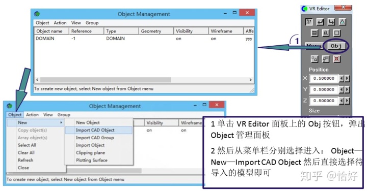
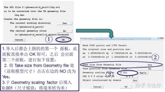
2) Copy the model file to the opened folder, choose the file, click “Open”. ---- “OK” ----“Take size from Geometry file: Yes”; “Geometry scaling factor:0.001”-scale millimeter to meter.
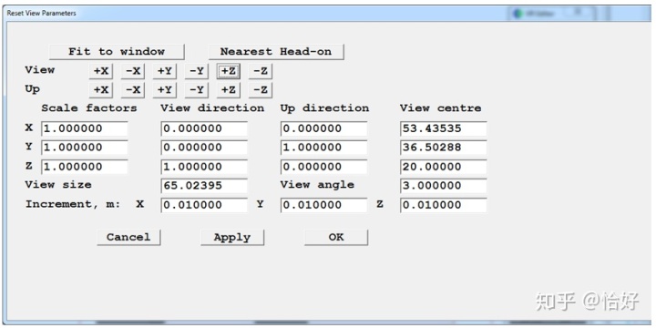
3)Fit to window:
“Reset” --- “Fit to window”, +Z ----- “Apply” --- OK. Press left mouse button to rotate the model, change views.
(3)Set domain size: (计算区域调整)
计算原则: X = Domain size X + 4H~6H (H=Building Height);
Y = Domain size Y + 4H~6H (H=Building Height);
Z = 3H (H=Building Height);
(4)Set Building Position: 模型居中设定
X = (Domain Size X – Building Size X) / 2
Y = (Domain Size Y – Building Size X) / 2
Z = 0
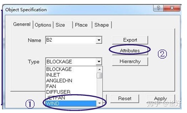
(5)Set wind boundary: 设置风边界
Object—New—New object ---- Type: Wind ---- Attribute
Wind speed 风速: 3.0m/s;
Wind direction 风向: North
Profile type: power Law;
Include open sky: Yes.
OK ----- Apply ---- OK
(6)Set Grid 设置网格
1) 细化 1.5m行人高度区域(是为了细化中间建筑区和1.5米高度内网格数量)
Object—New—New object ---- Type: Null ---- Apply ---- OK.
Set size of “Null”: Choose “Null” ---- X = (Domain Size X) / 2 +H
Y = (Domain Size Y) / 2 +H
Z = 1.5m
Set position of “Null”: Choose “Null” ---- X = (Domain Size X – Null Size X) / 2
Y = (Domain Size Y – Null Size Y) / 2
Z = 0
2) cell number网格数量
a. set “object effect grid”: object --- double click 要设置的object ---- options --- object effect grid
Building: only tick Z direction;
Null: tick all the X, Y, Z direction.
b. XY plane grid set
因设置了Null,水平面被分为中间Null区域和四周区域,为减少总体的网格数量,各个区域网格数设置不同。
双击Null网格区域,进去该区域的网格设置窗口 —— 分别单击X,Y direction,选free all (意思是该区域网格全部均匀分配),Z不改。——OK之后回到Grid Mesh Setting 窗口,在Cell in region 中输入X, Y方向方格数(3m一个格子,即Null的x, y除以3)——OK,该区域结束。
分别设置Null外面四个角的格子数,数量少一些。之后设置Null上下左右相邻的区域的“Power / Ratio”,通常设正负1.1-2(含义是相邻区域网格宽度渐变过渡,正负是渐变的方向,根据实际情况调整),到此水平面网格设好了。
c. 垂直高度网格设置 (将“铅笔”位置改到中间)
· 1.5米高度:单击——数量改为3个。
· 建筑物高度区域:cell in region = 建筑高度/2米 (2米一个格子)
· 建筑物以上区域:设置少量格子数,设置power ratio.
Done.
(7)设置计算参数
Menu ---- Models:
· Energy Equation 求解温度: OFF
· Turbulence model湍流模型: KECHEN.
· Numerics: Total number of iterations: 迭代步数。1000 ~ 2000;(现场可以先用100或200做试验。)
3. Running solver 运行计算
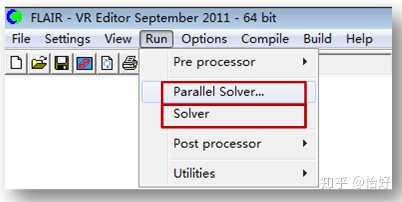
Parallel Solver: 多核计算
Solver:单核计算
通常用多核计算:2核或4核。
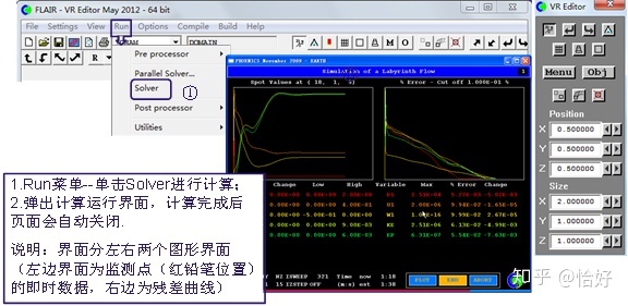
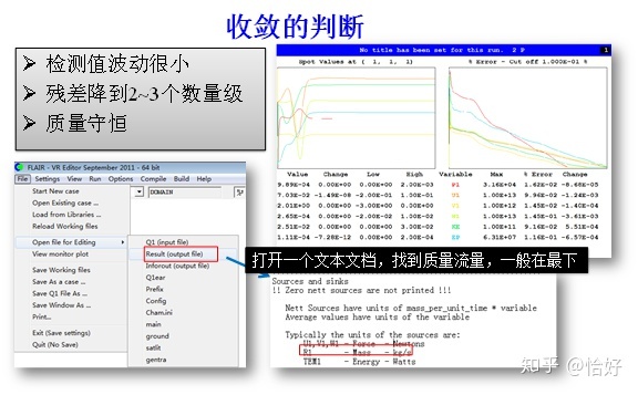
数据收敛
4. View Results 查看结果
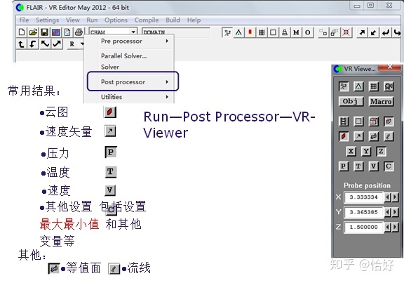
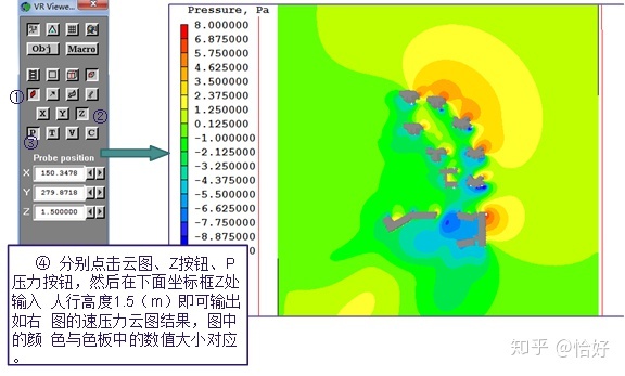
(1) Pressure: 风压
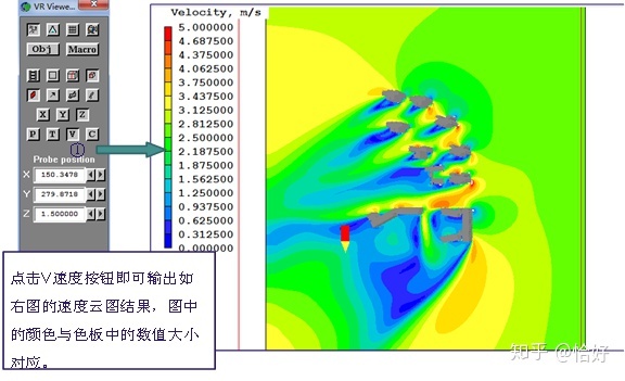
(2) Velocity: 风速云图
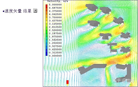
(3) Vector diagram: 风速矢量图
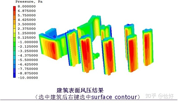
(4) Building surface pressure:
如果大家觉得本篇文字对你有所帮助,就请多多关注我哦!后续还会有其他实用文章分析。


 833
833

 被折叠的 条评论
为什么被折叠?
被折叠的 条评论
为什么被折叠?
 到【灌水乐园】发言


