


STM32 USB-FS-Device firmware library
This section describes the firmware interface (called USB-FS-Device Library) used to
manage the STM32 USB 2.0 full-speed device peripheral. In the rest of the document, it will be referred to as USB-FS_Device peripheral .
The main purpose of this firmware library is to provide resources to ease the development of applications for each USB transfer type using the USB-FS_Device peripheral in the STM32 microcontroller families.
本节描述固件接口(称为USB FS设备库)。
管理STM32 USB 2全速设备外围设备。在文档的其余部分中,它被称为usb-fs_deviceyin固件库。这个固件库的主要目的是提供资源来简化每个使用STM32 usb-fs_device为USB外设传输类型的的的开发。

The STM32_USBFS_Device_Driver is compliant with the USB 2.0 specification and is separate from the standard STM32 standard peripheral library。
3.2 USB-FS_Device peripheral interface
Table 4 presents the USB-FS_Device peripheral interface modules.

3.2.1 usb_reg(.h, .c)
The usb_regs module implements the hardware abstraction layer, it offers a set of basic
functions for accessing the USB-FS_Device peripheral registers.
Note: The available functions have two call versions:
● As a macro: the call is: _NameofFunction(parameter1, …)
● As a subroutine: the call is: NameofFunction(parameter1, …)
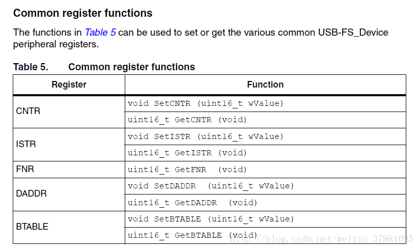
Common register functions
The functions in Table 5 can be used to set or get the various common USB-FS_Device peripheral registers.
Endpoint register functions
All operations with endpoint registers can be obtained with the SetENDPOINT and GetENDPOINT functions. However, many functions are derived from these to offer theadvantage of a direct action on a specific field.
a) Endpoint set/get value
SetENDPOINT : void SetENDPOINT(uint8_t bEpNum,uint16_t wRegValue)
bEpNum = Endpoint number, wRegValue = Value to write
GetENDPOINT : uint16_t GetENDPOINT(uint8_t bEpNum)
bEpNum = Endpoint number
return value: the endpoint register value
b) Endpoint TYPE field
The EP_TYPE field of the endpoint register can assume the defined values below:
*#define EP_BULK (0x0000) // Endpoint BULK
*#define EP_CONTROL (0x0200) // Endpoint CONTROL
*#define EP_ISOCHRNOUS (0x0400) // Endpoint ISOCHRONOUS
*#define EP_INTERRUPT (0x0600) // Endpoint INTERRUPT
SetEPType : void SetEPType (uint8_t bEpNum, uint16_t wtype)
bEpNum = Endpoint number, wtype = Endpoint type (value from the
above define’s)
GetEPType : uint16_t GetEPType (uint8_t bEpNum)
bEpNum = Endpoint number
return value: a value from the above define’s
c) Endpoint STATUS field
The STAT_TX / STAT_RX fields of the endpoint register can assume the defined
values below:
*#define EP_TX_DIS (0x0000) // Endpoint TX DISabled
*#define EP_TX_STALL (0x0010) // Endpoint TX STALLed
*#define EP_TX_NAK (0x0020) // Endpoint TX NAKed
*#define EP_TX_VALID (0x0030) // Endpoint TX VALID
*#define EP_RX_DIS (0x0000) // Endpoint RX DISabled
*#define EP_RX_STALL (0x1000) // Endpoint RX STALLed
*#define EP_RX_NAK (0x2000) // Endpoint RX NAKed
*#define EP_RX_VALID (0x3000) // Endpoint RX VALID
SetEPTxStatus : void SetEPTxStatus(uint8_t bEpNum,uint16_t wState)
SetEPRxStatus : void SetEPRxStatus(uint8_t bEpNum,uint16_t wState)
bEpNum = Endpoint number, wState = a value from the above define’s
GetEPTxStatus : uint16_t GetEPTxStatus(uint8_t bEpNum)
GetEPRxStatus : uint16_t GetEPRxStatus(uint8_t bEpNum)
bEpNum = endpoint number
return value:a value from the above define’s
d) Endpoint KIND field
SetEP_KIND : void SetEP_KIND(uint8_t bEpNum)
ClearEP_KIND : void ClearEP_KIND(uint8_t bEpNum)
bEpNum = endpoint number
Set_Status_Out : void Set_Status_Out(uint8_t bEpNum)
Clear_Status_Out : void Clear_Status_Out(uint8_t bEpNum)
bEpNum = endpoint number
SetEPDoubleBuff : void SetEPDoubleBuff(uint8_t bEpNum)
ClearEPDoubleBuff : void ClearEPDoubleBuff(uint8_t bEpNum)
bEpNum = endpoint number
Correct Transfer Rx/Tx fields
ClearEP_CTR_RX : void ClearEP_CTR_RX(uint8_t bEpNum)
ClearEP_CTR_TX : void ClearEP_CTR_TX(uint8_t bEpNum)
bEpNum = endpoint number
e) Data Toggle Rx/Tx fields
ToggleDTOG_RX : void ToggleDTOG_RX(uint8_t bEpNum)
ToggleDTOG_TX : void ToggleDTOG_TX(uint8_t bEpNum)
bEpNum = endpoint number
f) Address field
SetEPAdress : void SetEPAddress(uint8_t bEpNum,uint8_t bAddr)
bEpNum = endpoint number
bAddr = address to be set
GetEPAdress : uint8_t GetEPAddress(uint8_t bEpNum)
bEpNum = endpoint number
Buffer description table functions
These functions are used in order to set or get the endpoints’ receive and transmit bufferaddresses and sizes.
a) Tx/Rx buffer address fields
SetEPTxAddr : void SetEPTxAddr(uint8_t bEpNum,uint16_t wAddr);
SetEPRxAddr : void SetEPRxAddr(uint8_t bEpNum,uint16_t wAddr);
bEpNum = endpoint number
wAddr = address to be set (expressed as PMA buffer address)
GetEPTxAddr : uint16_t GetEPTxAddr(uint8_t bEpNum);
GetEPRxAddr : uint16_t GetEPRxAddr(uint8_t bEpNum);
bEpNum = endpoint number
return value : address value (expressed as PMA buffer address)
b) Tx/Rx buffer counter fields
SetEPTxCount : void SetEPTxCount(uint8_t bEpNum,uint16_t wCount);
SetEPRxCount : void SetEPRxCount(uint8_t bEpNum,uint16_t wCount);
bEpNum = endpoint number
wCount = counter to be set
GetEPTxCount : uint16_t GetEPTxCount(uint8_t bEpNum);
GetEPRxCount : uint16_t GetEPRxCount(uint8_t bEpNum);
bEpNum = endpoint number
return value : counter value
Double-buffered endpoints functions
To obtain high data-transfer throughput in bulk or isochronous modes, double-buffered mode has to be programmed. In this operating mode some fields of the endpoint registers andbuffer description table cells have different meanings.
To ease the use of this feature several functions have been developed.
● SetEPDoubleBuff: An endpoint programmed to work in bulk mode can be set as
double-buffered by setting the EP-KIND bit. The function SetEPDoubleBuff()
accomplishes this task:
SetEPDoubleBuff : void SetEPDoubleBuff(uint8_t bEpNum);
bEpNum = endpoint number
● FreeUserBuffer: In double-buffered mode, the endpoints become mono-directional
and buffer description table cells of the unused direction are applied to handle a second
buffer.
Addresses and counters must be handled in a different way. Rx and Tx Addresses and
counter cells become Buffer0 and Buffer1 cells. Functions dedicated to this operating
mode are provided for in the library.
During a bulk transfer the line fills one buffer while the other buffer is reserved to the
application. A user application has to process data before the arrival of bulk needing a
buffer. The buffer reserved to the application has to be freed in time.
To free the buffer in use from the application, the FreeUserBuffer function is provided:
FreeUserBuffer: void FreeUserBuffer(uint8_t bEpNum, uint8_t
bDir);
bEpNum = endpoint number
为了获得高数据传输吞吐量的批量或同步模式,双缓冲模式必须被程序化。在这种操作模式下,端点寄存器的一些字段和缓冲区描述表单元格有不同的含 义。
为了简化这个功能的使用,已经开发了几个函数。
●setepdoublebuff:端点 in bulk mode(在批处理)工作模式下可通过设置ep-kind位来实现为双缓冲功能
●freeuserbuffer:双缓冲模式下,端点成为单方向的端点,没有定义使用方向的缓冲区描述表单元格作为第二个缓冲区。
地址和计数器必须用不同的方式处理。RX和TX地址和计数单元使用buffer0和buffer1不同的工作缓冲区。函数在库函数中提供专用于此操作模式的功能函数。
在批量传输过程中,该行填充一个缓冲区,而另一个缓冲区则保留给应用。用户应用程序必须在到达需要批量的数据之前处理数据。预留给应用程序的缓冲区必须及时释放。
To free the buffer in use from the application, the FreeUserBuffer function is provided:
FreeUserBuffer: void FreeUserBuffer(uint8_t bEpNum, uint8_tbDir);
bEpNum = endpoint number
a) Double buffer addresses
These functions set or get buffer address value in the buffer description table for
double buffered mode.
SetEPDblBuffAddr : void SetEPDblBuffAddr(uint8_t
bEpNum,uint16_t wBuf0Addr,uint16_t wBuf1Addr);
SetEPDblbuf0Addr : void SetEPDblBuf0Addr(uint8_t
bEpNum,uint16_t wBuf0Addr);
SetEPDblbuf1Addr : void SetEPDblBuf1Addr(uint8_t
bEpNum,uint16_t wBuf1Addr);
bEpNum = endpoint number
wBuf0Addr, wBuf1Addr = buffer addresses (expressed as PMA
buffer addresses)
GetEPDblBuf0Addr : uint16_t GetEPDblBuf0Addr(uint8_t
bEpNum);
GetEPDblbuf1Addr : uint16_t GetEPDblBuf1Addr(uint8_t
bEpNum);
bEpNum = endpoint number
return value : buffer addresses
b) Double buffer counters
These functions set or get buffer counter value in the buffer description table for
double buffered mode.
SetEPDblBuffCount: void SetEPDblBuffCount(uint8_t bEpNum, uint8_t
bDir, uint16_t wCount);
SetEPDblBuf0Count: void SetEPDblBuf0Count(uint8_t bEpNum, uint8_t
bDir, uint16_t wCount);
SetEPDblBuf1Count: void SetEPDblBuf1Count(uint8_t bEpNum, uint8_t
bDir, uint16_t wCount);
bEpNum = endpoint number
bDir = endpoint direction
wCount = buffer counter
GetEPDblBuf0Count : uint16_t GetEPDblBuf0Count(uint8_t bEpNum);
GetEPDblBuf1Count : uint16_t GetEPDblBuf1Count(uint8_t bEpNum);
bEpNum = endpoint number
return value : buffer counter
c) Double buffer STATUS
The simple and double buffer modes use the same functions to manage the
Endpoint STATUS except for the STALL status for double buffer mode. This
functionality is managed by the function:
SetDouBleBuffEPStall: void SetDouBleBuffEPStall(uint8_t
bEpNum,uint8_t bDir)
bEpNum = endpoint number
bDir = endpoint direction
3.2.2 usb_int (.h , .c)
The usb_int module handles the correct transfer interrupt service routines; it offers the link
between the USB device protocol events and the library.
The STM32 USB-FS_Device peripheral provides two transfer routines:
● Low-priority interrupt: managed by the function CTR_LP() and used for control,
interrupt and bulk (in simple buffer mode).
● High-priority interrupt: managed by the function CTR_HP() and used for faster transfer
mode like Isochronous and bulk (in double buffer mode).
3.2.3 usb_mem (.h , .c)
The usb_mem copies a buffer data from the user memory area to the packet memory area
(PMA) and vice versa. It provides two different functions:
● void UserToPMABufferCopy(uint8_t *pbUsrBuf,uint16_t wPMABufAddr, uint16_t
wNBytes);
● void PMAToUserBufferCopy(uint8_t *pbUsrBuf,uint16_t wPMABufAddr, uint16_t
wNBytes);
Where:
● pbUsrBuf is the pointer to the user memory area generally in the product’s SRAM.
● wPMABufAddr is the address in PMA (512-byte packet memory area dedicated to
USB).
● wNBytes is the number of bytes to be copied.
USB-FS-Device_Driver medium layer
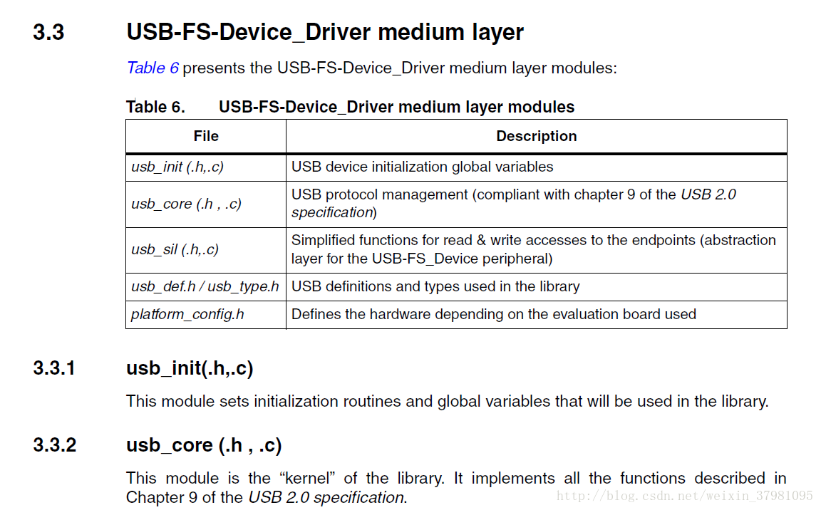
The available subroutines cover handling of USB standard requests related to the control
endpoint (ENDP0), offering the necessary code to accomplish the sequence of enumeration phase.
可用的子程序包括端点(endp0)usb处理与控制相关的标准请求,为完成枚举序列提供必要的代码
A state machine is implemented in order to process the different stages of the setup
transactions.
通过状态机来实现的不同状态情况下寄存器的状态配置转换。
The USB core module also implements a dynamic interface between the standard request
and the user implementation using the structure User_Standard_Requests.
USB核心模块user_standard_requests实现了标准请求和与用户实现使用的结构之间的动态接口。
The USB core dispatches the class specific requests and some bus events to user program
whenever it is necessary. User handling procedures are given in the Device_Property
structure.
USB核心将一些所需的类特定请求和一些总线事件分派给用户程序。通过操作给定的device_property结构体,User可以设计自己的程序。
The different data and function structures used by the kernel are described in the following paragraphs.
1. Device table structure
The core keeps device level information in the Device_Table structure. Device_Table
is of the type: DEVICE.
typedef struct _DEVICE {
uint8_t Total_Endpoint;
uint8_t Total_Configuration;
} DEVICE;
2. Device information structure
The USB core keeps the setup packet from the host for the implemented USB Device in
the Device_Info structure. This structure has the type: DEVICE_INFO.
typedef struct _DEVICE_INFO {
uint8_t USBbmRequestType;
uint8_t USBbRequest;
uint16_t_uint8_t USBwValues;
uint16_t_uint8_t USBwIndexs;
uint16_t_uint8_t USBwLengths;
uint8_t ControlState;
uint8_t Current_Feature;
uint8_t Current_Configuration;
uint8_t Current_Interface;
uint8_t Current_AlternateSetting;
ENDPOINT_INFO Ctrl_Info;
} DEVICE_INFO;
**An union uint16_t_uint8_t is defined to easily access some fields in the
DEVICE_INFO in either uint16_t or uint8_t format.**
typedef union {
uint16_t w;
struct BW {
uint8_t bb1;
uint8_t bb0;
} bw;
} uint16_t_uint8_t;
通过定义混合结构体变量uint16_t_uint8_t,可同时读取16bit或是8bit的设备信息
Description of the structure fields:
– USBbmRequestType is the copy of the bmRequestType of a setup packet
– USBbRequest is the copy of the bRequest of a setup packet
– USBwValues is defined as type: uint16_t_uint8_t and can be accessed through
3 macros:
*#define USBwValue USBwValues.w
*#define USBwValue0 USBwValues.bw.bb0
*#define USBwValue1 USBwValues.bw.bb1
USBwValue is the copy of the wValue of a setup packet
USBwValue0 is the low byte of wValue, and USBwValue1 is the high byte of
wValue.
– USBwIndexs is defined as USBwValues and can be accessed by 3 macros:
*#define USBwIndex USBwIndexs.w
*#define USBwIndex0 USBwIndexs.bw.bb0
*#define USBwIndex1 USBwIndexs.bw.bb1
USBwIndex is the copy of the wIndex of a setup packet
USBwIndex0 is the low byte of wIndex, and USBwIndex1 is the high byte of
wIndex.
– USBwLengths is defined as type: uint16_t_uint8_t and can be accessed
through 3 macros:
*#define USBwLength USBwLengths.w
*#define USBwLength0 USBwLengths.bw.bb0
*#define USBwLength1 USBwLengths.bw.bb1
USBwLength is the copy of the wLength of a setup packet
USBwLength0 and USBwLength1 are the low and high bytes of wLength,
respectively.
– ControlState is the state of the core, the available values are defined in
CONTROL_STATE.
– Current_Feature is the device feature at any time. It is affected by the
SET_FEATURE and CLEAR_FEATURE requests and retrieved by the
GET_STATUS request. User code does not use this field.
– Current_Configuration is the configuration the device is working on at any time.
It is set and retrieved by the SET_CONFIGURATION and GET_CONFIGURATION
requests, respectively.
– Current_Interface is the selected interface.
– Current_Alternatesetting is the alternative setting which has been selected for
the current working configuration and interface. It is set and retrieved by the
SET_INTERFACE and GET_INTERFACE requests, respectively.
– Ctrl_Info has type ENDPOINT_INFO.
Since this structure is used everywhere in the library, a global variable
– pInformation is defined for easy access to the Device_Info table, it is a pointer to the DEVICE_INFO structure
Actually, pInformation = &Device_Info
3. Device property structure
The USBcore dispatches the control to the user program whenever it is necessary.
User handling procedures are given in an array of Device_Property. The structure has
the type: DEVICE_PROP:
typedef struct _DEVICE_PROP {
void (*Init)(void);
void (*Reset)(void);
void (*Process_Status_IN)(void);
void (*Process_Status_OUT)(void);
RESULT (*Class_Data_Setup)(uint8_t RequestNo);
RESULT (*Class_NoData_Setup)(uint8_t RequestNo);
RESULT (*Class_Get_Interface_Setting)(uint8_t Interface,uint8_t
AlternateSetting);
uint8_t* (*GetDeviceDescriptor)(uint16_t Length);
uint8_t* (*GetConfigDescriptor)(uint16_t Length);
uint8_t* (*GetStringDescriptor)(uint16_t Length);
void* RxEP_buffer; /* This field is not used in current library version.
It is kept only for compatibility with previous versions */
uint8_t MaxPacketSize;
} DEVICE_PROP;
4. User standard request structure
The User Standard Request Structure is the interface between the user code and the
management of the standard request. The structure has the type:
USER_STANDARD_REQUESTS:
typedef struct _USER_STANDARD_REQUESTS {
void(*User_GetConfiguration)(void);
void(*User_SetConfiguration)(void);
void(*User_GetInterface)(void);
void(*User_SetInterface)(void);
void(*User_GetStatus)(void);
void(*User_ClearFeature)(void);
void(*User_SetEndPointFeature)(void);
void(*User_SetDeviceFeature)(void);
void(*User_SetDeviceAddress)(void);
} USER_STANDARD_REQUESTS;
If the user wants to implement specific code after receiving a standard USB Device
request he has to use the corresponding functions in this structure.
An application developer must implement three structures having the DEVICE_PROP,
Device_Table and USER_STANDARD_REQUEST types in order to manage class
requests and application specific controls. The different fields of these structures are
described in Section 3.3.4: usb_type.h / usb_def.h
3.3.3 usb_sil(.h, .c)
The usb_sil module implements an additional abstraction layer for USB-FS_Device
peripheral. It offers simple functions for accessing the Endpoints for Read and Write
operations.
Endpoint simplified write function
The write operation to an endpoint can be performed through the following function:
void USB_SIL_Write(uint32_t EPNum, uint8_t* pBufferPointer, uint32_t
wBufferSize);
The parameters of this function are:
● EPNum: Number of the IN endpoint related to the write operation
● pBufferPointer: Pointer to the user buffer to be written to the IN endpoint.
● wBufferSize: Number of data bytes to be written to the IN endpoint.
Depending on the peripheral interface, this function gets the address of the endpoint buffer
and performs the packet write operation.
Endpoint simplified read function
The read operation from an endpoint can be performed through the following function:
uint32_t USB_SIL_Read(uint32_t EPNum, uint8_t* pBufferPointer);
The parameters of this function are:
● EPNum: Number of the OUT endpoint related to the read operation
● pBufferPointer: Pointer to the user buffer to be filled with the data read form the OUT
endpoint.
Depending on the peripheral interface, this function performs two successive operations:
1. Gets the number of data received from the host on the related OUT endpoint
2. Copies the received data from the USB dedicated memory to the pBufferPointer
address.
Then the function returns the number of received data bytes to the user application.
3.3.4 usb_type.h / usb_def.h
These files provides the main types and USB definitions used in the library.
3.3.5 platform_config.h
This file is responsible for offering a specific configuration for each eval board. This file
should be copied to the application folder, where it can then be configured by the user.
3.4 Application interface
The modules of the Application interface are provided as a template, they must be tailored
by the application developer for each application. Table 7 shows the different modules used
in the application interface.

3.4.1 usb_conf(.h)
The usb_conf.h is used to customize the USB demos and to configure the device as follows:
● Define the number of endpoints to be used (through the define EP_NUM).
● Enable the use of Endpoints and event callback routines by commenting the relative
callback define (i.e. comment the define EP1_IN_Callback to enable and use this
function when a correct transfer occurs on endpoint 1, comment the define
INTR_SOFINTR_Callback in order to use and implement this function when an SOF
interrupt occurs…).
When a callback is to be used, its relative define in usb_conf.h fileshould be commented. Then, it should be implemented with the same name in the user application (no need to declare the callback function prototype as it is already declaredin the usb_istr.h file).
You can use the file usb_conf.h to:
– Configure the BTABLE and all endpoint addresses in the PMA (by modifying
and/or adding relative address defines: BTABLE_ADDRESS, ENDP0_RXADDR,
ENDP0_TXADDR …).
– Define the interrupts to enable them through the interrupt mask IMR_MSK.
3.4.2 usb_desc (.h, .c)
The usb_desc.c file should contain all the USB descriptors related to the application. The user has to set these descriptors according to the application proprieties and class.
In all available demos in the “STM32 USB-FS_Device developer kit” there is an example implementing a unique serial number string descriptor based on the STM32 Device Unique ID register (12 digits).
The default value of the serial number string descriptor is “STM32” and during the USB initialization the Get_SerialNum() function reads the Device Unique ID register and sets the serial number string descriptor.
For more details regarding the Device Unique ID register, please refer to Table 4.
3.4.3 usb_prop (.h , .c)
The usb_prop module is used for implementing the Device_Property, Device_Table and**USER_STANDARD_REQUEST** structures used by the USB core.
Device property implementation
The device property structure fields are described below:
● void Init(void): Init procedure of the USB-FS_Device peripheral. It is called once at
the start of the application to manage the initialization process.
● void Reset(void): Reset procedure of the USB peripheral. It is called when the macrocell receives a RESET signal from the bus. The user program should set up the endpoints in this procedure, in order to set the default control endpoint and enable it to receive.
● void Process_Status_IN(void): Callback procedure, it is called when a status in a stage is finished. The user program can take control with this callback to perform classand application-related processes.
● void Process_Status_OUT(void): Callback procedure, it is called when a status out stage is finished. As with Process_Status_IN, the user program can perform actions after a status out stage.
● RESULT (see note below) *(Class_Data_Setup)(uint8_t RequestNo): Callback procedure, it is called when a class request is recognized and this request needs a data stage. The core cannot process such requests. In this case, the user program gets the chance to use custom procedures to analyze the request, prepare the data and pass the data to the USB-FS_Device core for exchange with the host. The parameter RequestNo indicates the request number. The return parameter of this function has the type: RESULT. It indicates the result of the request processing to the core.
● RESULT (*Class_NoData_Setup)(uint8_t RequestNo) Callback procedure, it is called when a non-standard device request is recognized, that does not need a data stage. The core cannot process such requests. The user program can have the chance to use custom procedures to analyze the request and take action. The return parameter of this function has type: RESULT. It indicates the result of the request processing to the core.
● RESULT (*Class_GET_Interface_Setting)(uint8_t Interface, uint8_t
AlternateSetting): This routine is used to test the received set interface standard request. The user must verify the “Interface” and “AlternateSetting” according to their own implementation and return the USB_UNSUPPORT in case of error in these two fields.
● uint8_t* GetDeviceDescriptor(uint16_t Length): The core gets the device descriptor.
● uint8_t* GetConfigDescriptor(uint16_t Length): The core gets the configuration descriptor.
● uint8_t* GetStringDescriptor(uint16_t Length): The core gets the string descriptor.
● uint16_t MaxPacketSize: The maximum packet size of the device default control endpoint.
Note: The RESULT type is the following:
typedef enum _RESULT {
USB_SUCCESS = 0,/* request process sucessfully */
USB_ERROR, /* error
USB_UNSUPPORT, /* request not supported
USB_NOT_READY/* The request process has not been finished,*/
/* endpoint will be NAK to further requests*/
} RESULT;
Description of the structure fields:
● Total_Endpoint is the number of endpoints the USB application uses.
● Total_Configuration is the number of configurations the USB application has.
USER_STANDARD_REQUEST implementation
This structure is used to manage the user implementation after receiving all standard requests (except Get descriptors). The fields of this structure are:
● void (*User_GetConfiguration)(void): Called after receiving the Get Configuration Standard request.
● void (*User_SetConfiguration)(void): Called after receiving the Set Configuration Standard request.
● void (*User_GetInterface)(void): Called after receiving the Get interface Standard request.
● void (*User_SetInterface)(void): Called after receiving the Set interface Standard request.
● void (*User_GetStatus)(void): Called after receiving the Get interface Standard request.
● void (*User_ClearFeature)(void): Called after receiving the Clear Feature Standard request.
● void (*User_SetEndPointFeature)(void): Called after receiving the set Feature Standard request (only for endpoint recipient).
● void (*User_SetDeviceFeature)(void): Called after receiving the set Feature Standard request (only for Device recipient).
● void (*User_SetDeviceAddress)(void): Called after receiving the set Address Standard request.
3.4.4 usb_endp (.c)
USB_endp module is used for:
● Handling the CTR “correct transfer” routines for endpoints other than endpoint 0 (EP0) for the USB-FS_Device peripheral
For enabling the processing of these callback handlers a pre-processor switch named EPx_IN_Callback (for IN transfer) or EPx_OUT_Callback (for OUT transfer) or EPx_RX_ISOC_CALLBACK (for Isochronous Out transfer) must be defined in the USB_conf.h file.
3.4.5 usb_istr(.c)
USB_istr module provides a function named USB_Istr() which handles all USB interrupts.
For each USB interrupt source, a callback routine named XXX_Callback (for example, RESET_Callback) is provided in order to implement a user interrupt handler. To enable the processing of each callback routines, a preprocessor switch named XXX_Callback must be defined in the USB configuration file USB_conf.h.
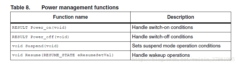
3.4.6 usb_pwr (.h , .c)
This module manages the power management of the USB device. It provides the functions shown in Table 8.
3.5 Implementing a USB-FS_Device application using the STM32 USB-FS-Device library
3.5.1 Implementing a no-data class-specific request
All class-specific requests without a data transfer phase implement the field RESULT (*Class_NoData_Setup)(uint8_t RequestNo) of the structure device property. The USBbRequest of the request is available in the RequestNo parameter and all other request fields are stored in the device info structure. The user has to test all request fields. If the request is compliant with the class to implement,the function returns the USB_SUCCESS result. However if there is a problem in the request,the function returns the UNSUPPORT result status and the library responds with a STALL
handshake.
3.5.2 How to implement a data class-specific request
In the event of class requests requiring a data transfer phase, the user implementation reports to the USB-FS-Device library the length of the data to transfer and the data location in the internal memory (RAM if the data is received from the host and, RAM or Flash
memory if the data is sent to the host). This type of request is managed in the function:
RESULT (*Class_Data_Setup)(uint8_t RequestNo).
For each class data request the user has to create a specific function with the format:
uint8_t* My_First_Data_Request (uint16_t Length)
If this function is called with the Length parameter equal to zero, it sets the pInformation->Ctrl_Info.Usb_wLength field with the length of data to transfer and returns a NULL pointer. In other cases it returns the address of the data to transfer. The
following C code shows a simple example:
uint8_t* My_First_Data_Request (uint16_t Length)
{
if (Length == 0)
{
pInformation->Ctrl_Info.Usb_wLength = My_Data_Length;
return NULL;
}
else
return (&My_Data_Buffer);
}
The function RESULT (*Class_Data_Setup)(uint8_t RequestNo) manages all data
requests as described in the following C code:
RESULT Class_Data_Setup(uint8_t RequestNo)
{
uint8_t*(*CopyRoutine)(uint16_t);
CopyRoutine = NULL;
if (My_First_Condition)// test the filds of the first request
CopyRoutine = My_First_Data_Request;
else if(My_Second_Condition) // test the filds of the second request
CopyRoutine = My_Second_Data_Request;
/*
… same implementation for each class data requests
…
*/
if (CopyRoutine == NULL) return USB_UNSUPPORT;
pInformation->Ctrl_Info.CopyData = CopyRoutine;
pInformation->Ctrl_Info.Usb_wOffset = 0;
(*CopyRoutine)(0);
return USB_SUCCESS;
} /End of Class_Data_Setup /
3.5.3 How to manage data transfers in non-control endpoint
The management of the data transfer using a pipe that is not the default one (Endpoint 0) can be managed in the usb_end.c file.
The user has to uncomment the line corresponding to the endpoint (with direction) in the file usb_conf.h.


 7058
7058

 被折叠的 条评论
为什么被折叠?
被折叠的 条评论
为什么被折叠?
 到【灌水乐园】发言


