


 本文详述了UG后处理的步骤,包括创建新后处理文件、选择机床类型、设置程序头尾、修改程序头的刀具信息、加工时间和程序尾的加工时间显示。还涉及了UG与VERICUT的结合使用,以及后处理中刀具注释和时间的添加方法。
UG 后处理 (后面有点UG与VERICUT) 要适当的提高自己的英语水平
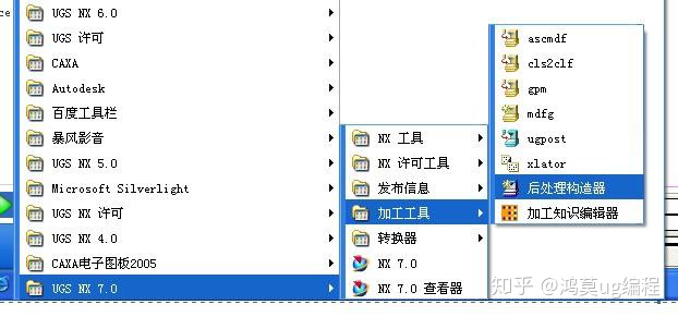
1.0.0:打开后处理 工具卡
1.2.0:进入创建后处理文件页面
1.2.1 创建一个新的后处理文件 这里输入文件名 (英文)
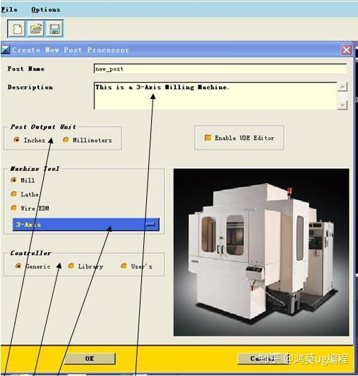
此区域 Inches 英制单位 Millimeters 公制设定
此区域 轴选项 3-轴 4-轴 或5轴 这里只讲解 3轴 通用设定
此区域为机床类型设定 Generic 通用的 Library 浏览自带机床
User’s 用户自定义
此区域描述你的后处理 单只能输入英文
选择完自己需要的格式后处理 单击OK 进入下一步
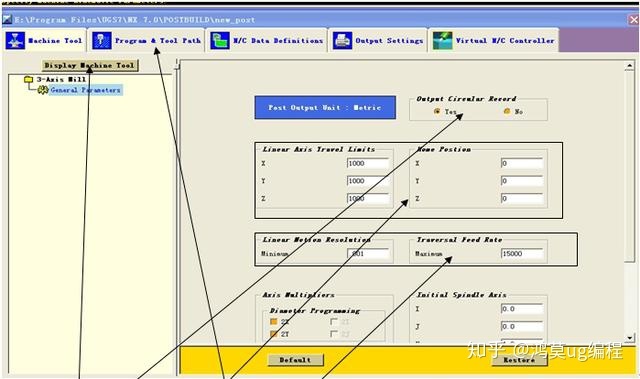
这一选项可以显示你选择机床类型 4轴 3轴 或你自定义的机床
这一区域是你的输出是否记录选项
此区域 左边为机床行程数据 右边为机床原点数据
此区域 左边为机床精度小数 右边为机床快速进给G00速度
其他选项默认就可以了
然后进入下一页面 点击这里
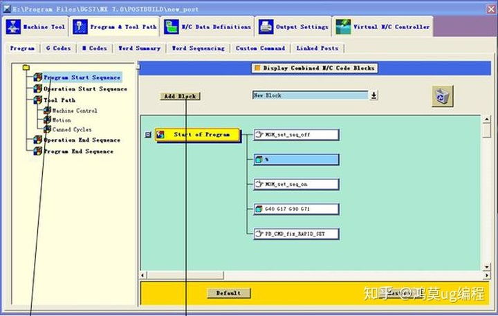
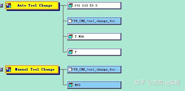
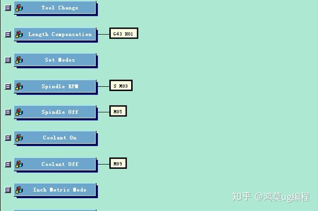
这一选项进行修改你的程序头 程序尾 中间换刀程序衔接 道具号 道具属性显示的添加 进行讲解
此选项为程序头选项 此选项为增加程序条命令 点击它 可以拖入程序条 就像这样 这里的垃圾桶 通样你不想要的此条可以删除
下面讲解 通用的编程设置 下面图片是默认的设置
此选项为N码关闭 此选项为N码开启 一般都是把这条 此选项 需要更改 改成你需要的 G40 G49 G80 G90既可 单击这条词条就可修改 进入下一画面 把不需要的拖入垃圾桶
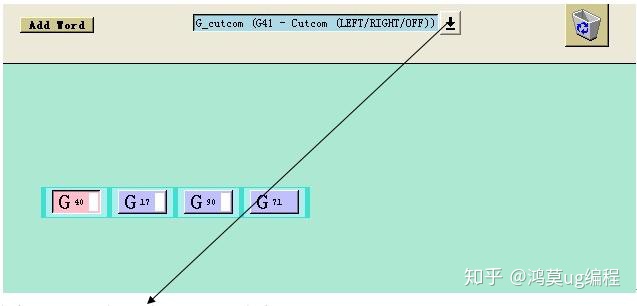
通过此选项里的代码 你可以找到你想要的 改好后点击OK既可
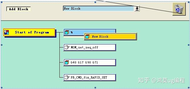
安全起见最好加入个Z轴回零命令 拉入一个词条框
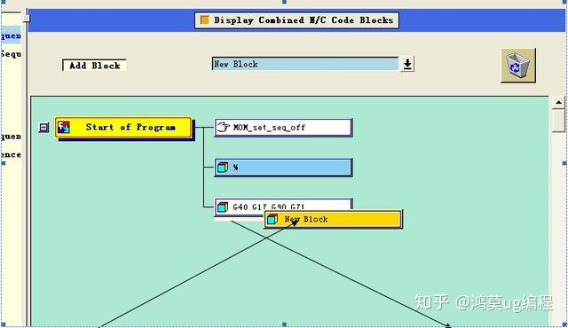
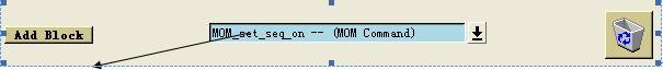
添加一个新的词条框 如果你想把词条框放在哪个 词条框的周围 只要看好 词条对应放置位置变白 既可松掉 鼠标 下面进入新词条选项里 点击这里可以加入你要的词条
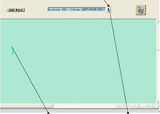
而我们需要的是 G00 G91 G28 Z0 命令 可以用文本形式输入就是这里选择 第二个选项 “TEXT” 文本 点击 Add word 拉入 这个区域 同样 变白放置 输入你要的文本G00 G91 G28 ZO 点击OK 既可程序头设定完成 就是这个效果看下图 如果需要加入O号下面编辑你的换刀过程 点击
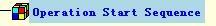
中文意思就是 操作开始步骤
在这里你可以加入你需要的道具信息 N号的开关 M8 M9的开关设置 G43H00等设置下面 先讲解 N号的加入
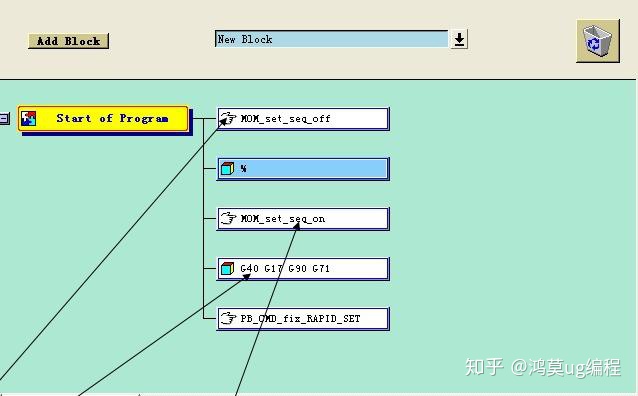
加入N号 我们只需要拉两个 N号开关 词条就可以
选择这一选项 拉到

上面 是N号开 然后拉入

在
下面既可下面加入刀具信息 找到这个选项操作员消息

拉入 N号关后面
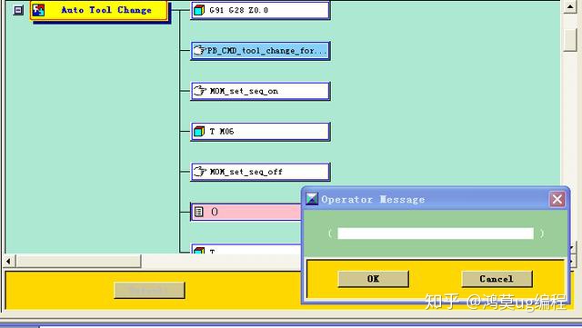
输入命令
MOM_output_literal “( 刀具名称:$mom_tool_name )”
MOM_output_literal “( 刀具直径:$mom_tool_diameter )”
MOM_output_literal “( 刀具R角半径:$mom_tool_corner_radius )”
想要哪个信息 就输入哪行 如果要两个以上 就飞边拉入词条输入
这项编辑 完毕
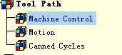
单击 蓝色的区域
机床控制 Machine Control 进入一下界面 我们只要在G43后加上M8既可 完成此项设定
然后点击

进程动作 设定 我们只需要修改中间的那个 G02 G03的
进入下一页面
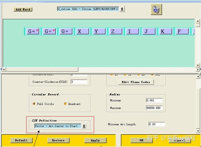
修改这里 把Vector-Arc Center to Start 该为Vector-Arc Start to Center
修改后OK 推出 不改出程序带R的 带圆的程序 就是乱做一团

这项无需修改 固定循环 孔功能 资料来源QQ三1五六1九三07四
All right! 最后让我们来修改 程序尾。可以加入加工时间 只是参考值的时间
点击

进入以下界面
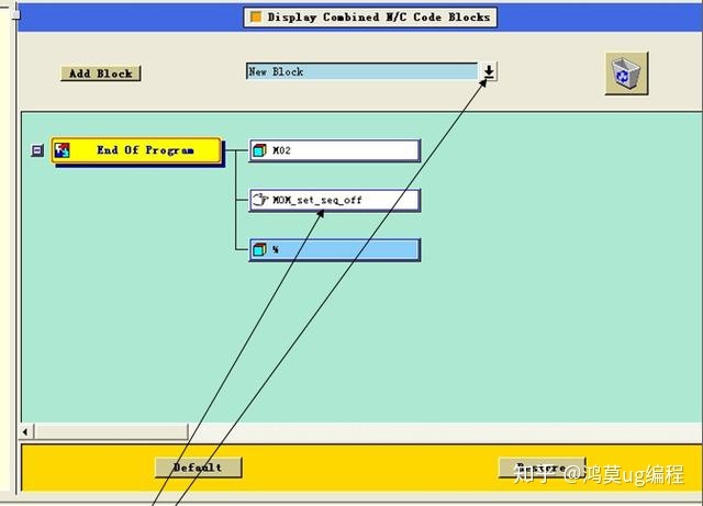
把不需要的拉入 垃圾桶 把M02 该为M30 或在前面加入 你要的 M5 M9 啊什么的 过加入 G00 G91 G28 Z0 最后加入 加工时间 It’s a interesting sequence!!~!~
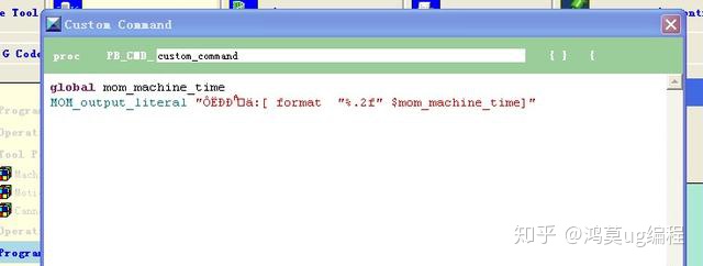
在这里找到 这个选项 Custom Command 拉入最后 输入 qunhao1四21三9八31
global mom_machine_time
MOM_output_literal “运行时间:[ format “%.2f” $mom_machine_time]”
点击OK 保存在一个你能找到的英文文件夹里 你的后处理可以用了 可以试试了 自己多研究研究很有趣的
UG与VERICUT
后处理中加刀具注释与时间方法
在后出里构造器里打开一个后处理文件,或者新建一个也行,然后在打开的后处理文件里添加变量,
如 global mom_tool_name // 刀具名
global mom_tool_diameter // 刀具直径
global mom_tool_corner1_radius // 刀具角半径
global mom_path_name // 路径名称
global mom_machine_time //加工时间
MOM_output_literal "(NAME mom_tool_name )"
MOM_output_literal "(D : [ format "%.2f" $mom_tool_diameter] )"
MOM_output_literal "(R :[ format "%.2f" $mom_tool_corner1_radius] )"
MOM_output_literal “(Path name: $mom_path_name)"
MOM_output_literal "(TIME :[ format "%.2f" $mom_machine_time])"
VERICUT7.0怎么样删除和添加定义的用户目录
在平时使用当中,我们会设置很多用户路径,但有些仿真文件被移动后,该用户目录就没有用处了,但还会在shortcut下拉列表框出现。我们可以通过编辑cgtech_62_user.prefs文件,来删除和添加定义的用户目录。
1.cgtech_62_user.prefs文件一般在C:Documents and Settings×××目录下,xxx是你的windows用户名。
2.打开cgtech_62_user.prefs文件,找到以Recent Work开头的行,这些就是我们设置的用户路径,你可以按照这种格式删除或添加用户路径。
3.还可以找到Toolpath Filters这一行,可以添加你想要的数控程序的后缀名。
4.用户还可以在这里编辑其它一些设置,但在设置前你最好知道这些设置是干什么用的!!!
有关海德汉M128的后处理更改
后处理里XYZ坐标变量分别改为
x mom_mcs_goto(0)
y mom_mcs_goto(1)
z mom_mcs_goto(2)
UG后处理刀补的正确输出方法
前一段时间搞ug 刀补的多刀处理问题,蛮头疼的,看到一强人Yeager给了一个方法
在Cutcom On里面增加一個Custom Command.,.填入"MOM_force once D",这个方法可以解决D号的模态省略的问题
,即在分层刀路里第二层G41/G42后没有D号的问题. 佩服啊!
关于G40的处理:
在Cutcom off项中删除G40 ,生成程序的效果如下:
N40 G0 G90 X-58. Y30. M03 S2000
N50 G43 Z3. H01
N60 Z1.077
N70 G1 Z-1.923 F250.
N80 G41 X-55. D01
N90 G2 X-50. Y35. I5. J0.0
N100 G1 X50.
N110 G2 X55. Y30. I0.0 J-5.
N120 G1 Y-30.
N130 G2 X50. Y-35. I-5. J0.0
N140 G40 G1 Y-37.54
N150 G0 Z1.077
N160 Y-38.
N170 Z-.846
N180 G1 Z-3.846
N190 G42 Y-35. D01
N200 G3 X55. Y-30. I0.0 J5.
N210 G1 Y30.
N220 G3 X50. Y35. I-5. J0.0
N230 G1 X-50.
N240 G3 X-55. Y30. I0.0 J-5.
N250 G40 G1 X-57.54
N260 G0 Z-.846
N270 X-58.
N280 Z-2.769
N290 G1 Z-5.769
N300 G41 X-55. D01
N310 G2 X-50. Y35. I5. J0.0
在fanuc 、mazak等机床上试验过,在fanuc系统上如果G41后没有D号,可以执行前一个模态的有效的D号,在G40后如果没有撤销刀补的直线段,刀补撤销没有问题,在G40这一句不产生移动,在下一句G1 x y 的语句执行
。如果将G41D1 单独列一行,可以对下一个坐标点进行补偿,但是补偿点的位置有误
在mazak系统中:G41D1单独列一行的语句运行后,立即对前一个坐标点进行补偿,G40也是如此,也就是说补的位置不是我们要补的位置。
所以我们为了程序的正确性,必须保证G41 D1 position
,G40 position 的格式。
做好刀补的方法:
总结:1.在Cutcom On里面增加一個Custom Command.,.填入"MOM_force once D",这个方法可以解决D号的模态省略的问题
2.删除Cutcom Off的G40。
3.在rapid move 里加入G40。
4.加入G54
5.刀具信息:global mom_tool_name
MOM_output_literal "(TOOL NAME $mom_tool_name)"
6.加工时间:global mom_machine_time
MOM_output_literal "(MACHINE TIME [format "%.2f" $mom_machine_time] MIN )"
7.在每个操作前加入行号及路径名$mom_path_name
on
路径名(operator message)
off
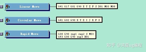
8.在rapid move中,需对rap1,rap2,rap3及m13强制输出.
($mom_output_file_basename)(刀轨文件名)
$mom_path_name(操作名)
9."MOM_force once M03" 。
10. 要用M8-Coolant Flood
11.螺纹铣:init_helix
uplevel #0 {
#
# This procedure will be executed automatically at the start of program and
# anytime it is loaded as a slave post of a linked post.
#
# This procedure can be used to enable your post to output helix.
# You can choose from the following options to format the circle
# block template to output the helix parameters.
#
set mom_sys_helix_pitch_type "rise_radian"
#
# The default setting for mom_sys_helix_pitch_type is "rise_radian".
# This is the most common. Other choices are:
#
# "rise_radian" Measures the rise over one radian.
# "rise_revolution" Measures the rise over 360 degrees.
# "none" Will suppress the output of pitch.
# "other" Allows you to calculate the pitch
# using your own formula.
#
# This custom command uses the block template circular_move to output
# the helix block. If your post uses a block template with a different
# name, you must edit the line that outputs the helix block.
#
# The following variable deines the output mode for helical records.
#
# FULL_CIRCLE -- This mode will output a helix record for each 360
# degrees of the helix.
# QUADRANT -- This mode will output a helix record for each 90
# degrees of the helix.
# LINEAR -- This mode will output the entire helix as linear gotos.
# END_POINT -- This mode will assume the control can define an entire
# helix in a single block.
set mom_kin_helical_arc_output_mode FULL_CIRCLE
MOM_reload_kinematics
#=============================================================
proc MOM_helix_move { } {
#=============================================================
global mom_pos_arc_plane
global mom_sys_cir_vector
global mom_sys_helix_pitch_type
global mom_helix_pitch
global mom_prev_pos mom_pos_arc_center
global PI
switch $mom_pos_arc_plane {
XY { MOM_suppress once K ; set cir_index 2 }
YZ { MOM_suppress once I ; set cir_index 0 }
ZX { MOM_suppress once J ; set cir_index 1 }
}
switch $mom_sys_helix_pitch_type {
none { }
rise_revolution { set pitch $mom_helix_pitch }
rise_radian { set pitch [expr $mom_helix_pitch / ($PI * 2.0)]}
other {
#
# Place your custom helix pitch code here
#
}
default { set mom_sys_helix_pitch_type "none" }
}
MOM_force once X Y Z
if {$mom_sys_helix_pitch_type != "none"} {
MOM_force once I J K
if {$mom_sys_cir_vector == "Vector - Arc Center to Start"} {
set mom_prev_pos($cir_index) 0.0
set mom_pos_arc_center($cir_index) $pitch
} elseif {$mom_sys_cir_vector == "Vector - Arc Start to Center"} {
set mom_prev_pos($cir_index) $pitch
set mom_pos_arc_center($cir_index) 0.0
} elseif {$mom_sys_cir_vector == "Unsigned Vector - Arc Center to Start"} {
set mom_prev_pos($cir_index) 0.0
set mom_pos_arc_center($cir_index) $pitch
} elseif {$mom_sys_cir_vector == "Absolute Arc Center"} {
set mom_pos_arc_center($cir_index) $pitch
}
}
#
# You may need to edit this line if you output more than one block
# or if you have changed the name of your circular_move block template
#
MOM_do_template circular_move
} ;# MOM_helix_move
} ;# uplevel
END


 6619
6619

 被折叠的 条评论
为什么被折叠?
被折叠的 条评论
为什么被折叠?
 到【灌水乐园】发言


