


Verilog代码中,每一个bit都对应电路的一部分。
模块的声明
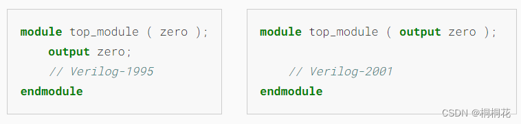
两种端口声明语法风格:
- Verilog-2001:更容易阅读并减少拼写错误
- verilog-1995:版本比较老
下面的两个模块声明是可以接受的和等价的:
声明一个模块
// top_module模块名
//in,out 端口名
module top_module( input in, output out );

endmodule
模块和端口声明创建电路框架和端口。
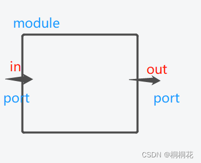
模块上的端口port
模块上的端口有方向(通常是input或output)
- input port:由模块外界的一些信号驱动
- output port:驱动外界的一些信号。
从模块内部的视角看
- input port是一个driver或者source
- output port是一个sink

wire
wires (和其他 signals) 是有方向的( directional)(和普通的物理线不一样)
这意味这信息在一个方向上传递,即从source端(通常只有一个)传输到sink端(多个)
(source经常被称为diver,将值驱动到wire上)
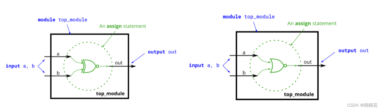
连续赋值(continuous assignment) assign语句
assign left_side = right_side;
//右边信号的值被驱动到左边的wire上赋值(assignment)是“连续的”,即使右边的值发送了变化,赋值也一直继续。
连续赋值不是one-time event。
module top_module( input in, output out );
    assign out = in ;//把in和out使用wire连接
endmodule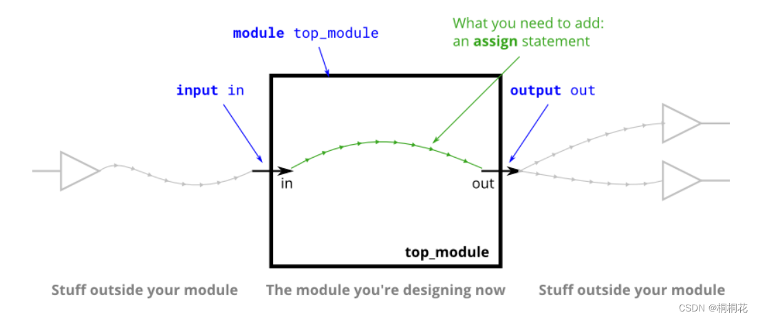
模块内部元件的连接
这里以 类型 wire 的信号举例,其他类型的信号和变量,它们也是以相同的方式声明
随着电路变得越来越复杂,你将需要电线把内部元件连接在一起。
当您需要使用 wire时,您应该在首次使用它之前在模块主体中的某个地方声明它。
举例:
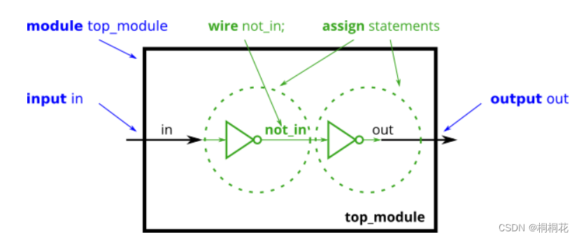
module top_module (
    input in,              // Declare an input wire named "in"
    output out             // Declare an output wire named "out"
);

    wire not_in;           // Declare a wire named "not_in"

    assign out = ~not_in;  // Assign a value to out (create a NOT gate).
    assign not_in = ~in;   // Assign a value to not_in (create another NOT gate).

endmodule   // End of module "top_module"
模块内部的运算
逻辑操作符
逻辑操作符的计算结果是一个 1bit 的值,0 表示假,1 表示真,x 表示不确定。
逻辑操作符主要有 3 个:
- &&(逻辑与)
- ||(逻辑或)
- !(逻辑非)
注意:
- 如果一个操作数不为 0,它等价于逻辑 1;
- 如果一个操作数等于 0,它等价于逻辑 0。
- 如果一个操作数任意一位为 x 或 z,它等价于 x。
- 如果任意一个操作数包含 x,逻辑操作符运算结果不一定为 x。
按位操作符
按位操作符对 2 个操作数的每 1bit 数据进行按位操作。
按位操作符包括:
- 取反(~)(只有一个操作数,它对操作数的每 1bit 数据进行取反操作。)
- 与(&)
- 或(|)
- 异或(^)
- 同或(~ ^)(Xnor gate同或门)
注意:
如果 2 个操作数位宽不相等,则用 0 向左扩展补充较短的操作数。
举例:
module gate(
	input  a,
	input  b,
	output y
   );
    assign y = a & b;//与门
    assign y = a | b;//或门
    assign y = ~a;//非门
    assign y = a ^ b;//异或门
    assign y = ~(a ^ b);//同或门
endmodule
举例:
同或门和或非门


 1432
1432


 被折叠的 条评论
为什么被折叠?
被折叠的 条评论
为什么被折叠?
 到【灌水乐园】发言


