


廖昱博
, 刘进元
, 蔡厚智
, 白雁力
, 付文勇
, 陈家堉
, 郭泉良
. . 磁聚焦变像管像场弯曲的改善研究. 光学学报, 2017, 44(10): 1004004-。
Liao Yubo
, Liu Jinyuan
, Cai Houzhi
, Bai Yanli
, Fu Wenyong
, Chen Jiayu
, Guo Quanliang
. . Improvement of Field Curvature in Magnetic-Focusing Image Converter Tube. Acta Agronomica Sinica, 2017, 44(10): 1004004-.

磁聚焦变像管像场弯曲的改善研究
廖昱博1,2, 刘进元1,*, 蔡厚智1, 白雁力1, 付文勇1, 陈家堉1, 郭泉良1
1深圳大学光电子器件与系统教育部重点实验室, 广东 深圳 518060
2赣南师范大学物理与电子信息学院, 江西 赣州 341000
摘要
研制大面积阴极磁聚焦分幅变像管。在2∶1电子光学倍率下,研究单磁透镜和双磁透镜成像的像场弯曲。基于光学透镜成像原理,假设成像面形状不随激励微调而改变,推导了离轴点最佳成像位置与激励变化的近似关系式,并由此提出一种测量并减小像管像场弯曲的方法;借助Matlab编程模拟了像管各离轴点的最佳成像位置,拟合得到成像曲面方程,并利用所提出的像场弯曲测量方法进行了测试验证。结果表明,在一定视场范围内,计算机模拟与实验测试结果比较接近。单、双磁透镜下的最佳成像面均为旋转抛物面,但双磁透镜成像像场弯曲比单磁透镜有明显的改善。
关键词
超快光学; 变像管; 短磁聚焦; 空间性能; 像场弯曲
Improvement of Field Curvature in Magnetic-Focusing Image Converter Tube
Liao Yubo1,2, Liu Jinyuan1,*, Cai Houzhi1, Bai Yanli1, Fu Wenyong1, Chen Jiayu1, Guo Quanliang1
1Key Laboratory of Optoelectronic Devices and Systems, Ministry of Education, Shenzhen University, Shenzhen, Guangdong 518060, China
2School of Physics and Electronic Information, Gannan Normal University, Ganzhou, Jiangxi 341000, China
Abstract
A large cathode magnetic-focusing framing image converter tube is designed and developed. The field curvatures of single magnetic lens and double magnetic lens systems are investigated at electron optical magnification of 2∶1. Based on optical lens imaging principle, the approximate relational expressions of the imaging excitation variation with the best image positions of the off-axis object are derived in the cases of single magnetic lens and separated double magnetic lens systems. It is assumed that the shape of image surface does not change with excitation in a certain scope. Accordingly, a method of field curvature measurement and decrease is proposed. Then, by virtue of Matlab programming, the best image positions for off-axis point objects are simulated, and the image surface equations are fitted, which are experimentally verified by use of the proposed method of field curvature measurement. It is showed that computer simulations agree with the experimental results within a certain field of view. Both of the best image surfaces of two systems are paraboloids of revolution. But the field curvature of double magnetic lens system is obviously smaller than that of single magnetic lens system.
Key words
ultrafast optics; image converter tube; short magnetic focusing; spatial performance; field curvature
论文信息
doi:10.3788/CJL201744.1004004
OCIS codes:
320.7100; 040.1490; 230.025; 110.2960
*
作者简介: 廖昱博(1982—),男,博士,讲师,主要从事超快诊断技术方面的研究。E-mail: bobocome@126.com。*通信联系人。E-mail: ljy@szu.edu.cn
收稿日期:2017-05-19
基金项目:国家自然科学基金、深圳市科技计划JCYJ20160608173121055,JCYJ20170302153912966
1 引言
X射线分幅相机利用变像管来实现图像的光电转换、脉冲选通以及图像增强, 是一种同时具有亚纳秒时间分辨和二维空间分辨能力的高灵敏度诊断设备。其借助光电阴极实现波长转换, 响应波段覆盖紫外光到X射线区, 广泛应用于X射线激光、惯性约束核聚变(ICF)、Z-箍缩(Z-P)以及强场物理等[重大研究领域中。
在超快诊断应用中, 时间分辨和空间分辨是衡量分幅变像管性能的两个重要技术指标。特别是ICF等研究的进一步发展, 对变像管相机的时空分辨提出了更高的要求, 进而加快了变像管技术的革新。传统微通道板(MCP)选通分幅像管的空间分辨率约为20 lp/mm(50 μm), 时间分辨率为35~100 ps[。Hilsabeck等[将脉冲展宽技术(PDT)和MCP行波选通技术相结合, 成功研制了时间展宽分幅相机。这种像管的光电阴极与MCP在漂移区分开。当X光脉冲照射到阴极上, 激发的光电子信号在阴栅之间的斜坡电压脉冲的作用下产生速度梯度, 使信号前沿部分比后沿部分具有更大的速度。经过漂移区后, 光电子束在时间上被展宽, 并通过长磁透镜将其成像在MCP微带上, 在快门脉冲的选通作用下, 时间分辨率可达5 ps。然而, 其动态空间分辨率约为3.3 lp/mm(300 μm)。在此基础上改进磁透镜结构, 在电子光学设计中引入一个短磁透镜替代长磁聚焦, 研制了短磁聚焦时间展宽分幅像管[, 其时间分辨率达到11 ps, 动态空间分辨率优于10 lp/mm(100 μm)[。但是, 该像管在阴极远轴区的空间分辨不理想, 存在明显的像场弯曲(简称场曲, FC), 无法用平面接收屏获取平面物体在整个视场范围的清晰成像, 进而影响其空间分辨能力, 缩小了像管的有效成像范围。因此, 深入研究像管的场曲并设法减小场曲, 具有非常重要的理论价值和现实意义。
在所研制的短磁聚焦分幅像管的基础上, 本文通过理论分析、计算机模拟与实验测试相结合的方法研究像管的场曲。基于透镜成像原理, 分别推导出表征单、双磁透镜场曲的近似关系式。结合计算机模拟与实验测试进行验证, 探讨如何减小像管场曲。
2 像管场曲的理论分析
电子束的场曲是由远轴区与近轴区的聚焦能力不同造成的[。离轴越远的电子受到的电磁场作用越强, 其聚焦位置因离轴距离不同, 不同程度地偏离理想成像平面, 形成一个凹向物方的曲面, 故可以用各离轴点最佳成像位置与高斯像面的轴向距离来度量场曲。基于透镜成像原理, 结合实际测试条件, 在保持物透镜、磁透镜以及平面接收屏三者位置均不变的情况下, 根据离轴距离与其最佳成像激励的关系, 即可求出各离轴像点对应的轴向偏离。以下分别分析经单磁透镜和双磁透镜后成像缩小为原来1/2时的场曲, 并将磁透镜作薄透镜处理, 假设励磁电流改变较小时成像面形状不变。
图1给出了单磁透镜成像的分析。与光学透镜成像关系相似, 物距s、像距s'以及焦距f之间满足高斯成像公式:
1/s+1/s'=1/f。(1)
图1
Fig. 1 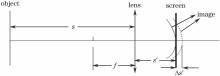
图1 单磁透镜成像的场曲分析Fig. 1 Field curvature analysis of single magnetic lens system
对于短磁透镜, 焦距与励磁电流之间近似满足[
f=k/I2,(2)k=65VR/N2,(3)
式中V、R、N、I分别为电子束加速电压、磁透镜线圈的平均半径、线圈匝数以及励磁电流, 即在此条件下近轴区理想成像。 (1)式、 (2)式分别对励磁电流I求导, 且物距不随激励变化, 联立可得
ds'/s'2=-2IdI/k。(4)
考虑到励磁电流小幅度降低, 对其积分并整理后得
Δs'=-ΔI(s')1(s')0(I0+I)/k,(5)
式中I0和I分别是激励改变前后的电流, ΔI代表这一过程中电流的增量; (s')1和(s')0分别为励磁电流降低前后近轴区的像距, Δs'代表该过程中成像面的后移量。由此可见, 略微降低励磁电流, 近轴区成像面将沿轴后移。又因为成像面形状不变, “凹面”也将跟随整体后移。如果此时离轴h物点的最佳成像位置恰好落入接收屏, 则Δs'即为该离轴h物点成像面的轴向偏离, 记作(Δs')h。因电流改变较小, 前后的像距差别较小, 可近似为
(Δs')h=-ΔIs'2(I0+I)/k。(6)
双磁透镜成像的分析如图2所示, 其离轴成像面的轴向偏离可作类似分析。在此仅讨论两磁透镜中心间隔较大距离, 前透镜L1比较靠近物, 所成的中间像为虚像的情形。对于透镜L1, 满足成像关系:
1/s+1/s'=1/f1,(7)
对于透镜L2, 满足成像关系:
1/s2+1/s'=1/f2,(8)
其中, 中间像对透镜L2的物距为
s2=-s'1+d。(9)
在透镜L2的励磁电流I2不变的情况下, 略微减小L1的励磁电流I10至I1, 计算最终像距s'对I1的导数, 经积分运算和近似处理, 可得双磁透镜成像离轴h物点成像面的轴向偏离为
(Δs')h=-ΔIs'2(I10+I1)s'21/(ks22)。(10)
图2
Fig. 2 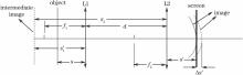
图2 双磁透镜成像的场曲分析Fig. 2 Field curvature analysis of double magnetic lens system
由此得到两种成像系统下离轴物点最佳成像位置偏离高斯像面的近似关系式。由(6)式和(10)式可知, 在近轴区最佳成像时, 调节励磁电流以使离轴不同距离的物点依次获得最佳成像, 从而间接测量像管的场曲。由于各离轴点的最佳成像位置难以直接测量, 故采用Matlab编程进行数值模拟并与之作对比。
3 变像管场曲的数值模拟
在2∶1 电子光学倍率下, 分别对单磁透镜和双磁透镜成像进行模拟。所模拟的像管结构包括光电阴极、栅网、短磁透镜、漂移管以及平面接收屏。阴极加-3 kV电压, 栅网接地, 阴栅加速区长1 mm。短磁透镜的结构是线圈密绕于铝芯, 外覆软铁屏蔽罩。线圈匝数N为1320, 磁透镜轴向宽为100 mm, 内直径为160 mm, 外直径为256 mm, 内壳上开有4 mm环形空气缝隙。漂移区管长为500 mm, 平面接收屏置于漂移管末端。建立空间直角坐标系, 将坐标原点定在漂移管中心。阴栅间加速场作匀强电场处理。当磁透镜缝隙较小时, 轴上磁感应强度分布为[
B=1.32μ0NIsech2(2.63z/D)/D,(11)
式中z为轴上点的坐标, I为磁透镜激励电流, D为磁透镜孔径, μ0为真空中的磁导率。由此, 再根据磁场的幂级数展开式, 可得轴外的磁场分布[。分别从阴极中心、离轴9, 15, 21, 27 mm等处随机抽样发射400个电子。光电子发射条件、电子轨迹的分析参照文献[
模拟过程中, 调整磁透镜激励和位置, 确定近轴区最佳成像时单磁透镜中心距离平面接收屏173 mm, 激励电流为0.311 A; 双磁透镜位置如图3(a)所示, 激励电流分别为0.218 A(前)和0.337 A(后)。两种成像系统轴上的磁场分布如图3(b)所示, 单、双磁透镜轴上最大的磁感应强度分别为4.3×10⁻³ T和4.6×10⁻³ T。由电子轨迹追迹法统计像面落点分布的均方根半径, 可得出两种系统阴极中心对应的空间MTF曲线, 进而求得当MTF降至0.1时, 单磁透镜成像阴极中心的空间分辨率为7.1 lp/mm, 双磁透镜成像为10.3 lp/mm。各离轴点的空间分辨率如图4所示。可见, 双磁透镜成像的空间分辨率高于单磁透镜成像。而且两种系统的轴外空间分辨率均明显低于近轴区的空间分辨率, 即都存在一定的场曲。在不改变磁透镜位置和激励的条件下, 沿轴负向平移接收屏, 依次得到各离轴点最佳成像位置的轴向坐标及其空间分辨率, 如表1所示。值得注意的是, 单磁透镜成像下即使在最佳成像面, 离轴15 mm以外点的空间分辨率也明显不如近轴区, 这主要是由像散造成的。由最佳成像位置的轴向坐标, 根据像管结构的旋转轴对称性, 可以描绘最佳成像的弯曲像面, 并拟合出相应的曲面方程。图5给出了两种成像系统弯曲像面的拟合结果, 图中的小圆圈代表轴外点对应的像点位置。单磁透镜成像的像面方程为z=249.001-0.083(x2+y2); 双磁透镜成像的像面方程为z=249.044-0.052(x2+y2)。显然, 两种成像条件下的最佳像面均为旋转抛物面, 并且单磁透镜的场曲明显大于双磁透镜成像。
图3
Fig. 3 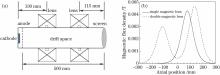
图3 (a)分幅变像管双磁透镜成像模型; (b)两种系统轴上的磁场分布Fig. 3 (a) Imaging model of framing converter tube with double magnetic lens system; (b) distribution of magnetic field of two systems on the axis
图4
Fig. 4 
图4 两种成像系统空间分辨率随离轴距离的变化Fig. 4 Variation of spatial resolution with off-axis distance for two systems
表1
Table 1
Simulated best image positions and spatial resolutions for off-axis point objects
Table 1 表1 离轴各点最佳成像位置与空间分辨率的模拟结果 Table 1 Simulated best image positions and spatial resolutions for off-axis point objects
表1离轴各点最佳成像位置与空间分辨率的模拟结果Table 1Simulated best image positions and spatial resolutions for off-axis point objectsImaging systemOff-axis distance /mmBest image position z /mmSpatial resolution /( lp·mm-1)Double magnetic lens9248.810.3
Double magnetic lens15246.710.3
Double magnetic lens21244.610.2
Double magnetic lens27237.49.1
Single magnetic lens9246.57.1
Single magnetic lens15243.03.9
Single magnetic lens21237.02.1
single magnetic lens27231.81.3
图5
Fig. 5 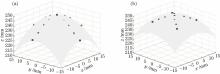
图5 (a)单磁透镜和(b)双磁透镜成像系统计算机模拟的弯曲成像面Fig. 5 Curved image surfaces obtained by computer simulation for (a) single magnetic lens and (b) double magnetic lens systems
4 变像管场曲的实验测试
变像管测试采用最新研制的大面积阴极像管, 其基本结构如图6所示。大面积阴极像管的物面具有尺寸为72 mm×12 mm的镀金微带结构, 像管末端装配有MCP、荧光屏和图像采集系统(CCD)。由于MCP具有尺寸为40 mm×8 mm的微带结构, 为确保阴极的像完全落在MCP上, 选择2∶1的成像倍率。为便于测试各离轴位置的空间分辨率, 利用光刻技术在阴极微带上规则地刻划各种空间频率的分辨率板, 每块分辨率板是尺寸为3 mm×3 mm的小方格, 其线对数分别为2, 5, 10, 15, 35 lp/mm。测试时, 直接用紫外(UV)灯作为光源采集静态图像。测试条件为:阴极电压-3.0 kV, MCP电压-560 V, 屏压+3.4 kV。磁透镜参照数值模拟的位置放置, 测得单磁透镜近轴成像的励磁电流为0.344 A; 双磁透镜近轴成像的励磁电流为0.240 A(前)和0.385 A(后)。实验时像管内部真空压强控制在1.0×10⁻³ Pa以下。
图6
Fig. 6 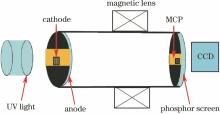
图6 实验测试系统基本结构图Fig. 6 Schematic of experimental system
图7和图8分别给出了不同励磁电流下单磁透镜和双磁透镜成像的测试结果。由图7可知, 单磁透镜成像离轴空间分辨率下降较快, 离轴12 mm以外区域就已模糊, 调节激励可使离轴15 mm获得最佳成像, 但其空间分辨率明显不如中心最佳成像时的分辨率。而离轴20 mm以外的最佳成像仅能观测到2 lp/mm条纹板模糊的轮廓, 并且此时近轴区的像质较差, 已不能分辨任何条纹信息。相比之下, 图8双磁透镜成像的离轴空间分辨率变化较为平缓, 离轴9 mm处仍有较好的空间分辨率。调整激励至离轴15 mm处最佳成像时, 近轴区的空间分辨率基本保持不变。此外, 27 mm处最佳成像时, 仍能清楚分辨2 lp/mm的条纹信息。这些与数值模拟的结果一致。由离轴距离与最佳激励的实验数据以及成像条件, 分别根据 (6) 式和(10) 式, 计算两种条件下各离轴点最佳成像位置, 结果如表2所示。绘制双磁透镜成像的弯曲像面如图9所示, 拟合的曲面方程为z=249.013-0.0503(x2+y2)。比较测量值与计算机模拟结果可知, 双磁透镜成像在离轴21 mm以内的偏差在1.6 mm之内; 单磁透镜成像在离轴15 mm处的偏差为1.7 mm。随着离轴距离增加, 其偏差逐渐增大。双磁透镜成像离轴27 mm和单磁透镜成像离轴21 mm的最佳成像位置偏差分别达到2.6 mm 和2.9 mm。离轴较远位置测量偏差较大的主要原因是先前假设成像面形状不随激励的微调而改变, 这只是激励相对改变较小时的合理近似。而对于远轴区来说, 激励的相对改变量已较大, 并且成像点靠近视场边缘也会给最佳激励值的确定带来较大的误差。尽管如此, 从测试结果来看, 该测量方法基本上能够反映场曲的总体轮廓, 因此, 在一定视场范围内的场曲测量结果是可靠的。
图7
Fig. 7 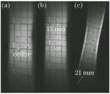
图7 不同励磁电流下的单磁透镜成像测试结果。(a) I=0.344 A; (b) I=0.341 A; (c) I=0.335 AFig. 7 Testing results under different excitation currents for single magnetic lens system. (a) I=0.344 A; (b) I=0.341 A; (c) I=0.335 A
图8
Fig. 8 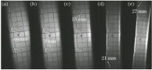
图8 不同励磁电流下的双磁透镜成像测试结果。(a) I1=0.240 A, I2=0.385 A; (b) I1=0.230 A, I2=0.385 A; (c) I1=0.220 A, I2=0.385 A; (d) I1=0.200 A, I2=0.385 A; (e) I1=0.180 A, I2=0.385 AFig. 8 Testing results under different excitation currents for double magnetic lens system. (a) I1=0.240 A, I2=0.385 A; (b) I1=0.230 A, I2=0.385 A; (c) I1=0.220 A, I2=0.385 A; (d) I1=0.200 A, I2=0.385 A; (e) I1=0.180 A, I2=0.385 A
表2
Table 2
Measurement results of best image positions for off-axis point objects
Table 2表2 离轴各点最佳成像位置的测量结果 Table 2 Measurement results of best image positions for off-axis point objects
表2离轴各点最佳成像位置的测量结果Table 2Measurement results of best image positions for off-axis point objectsImaging systemOff-axis distance /mm(Δs')h /mmBest image position z /mmDouble magnetic lens91.9248.1
Double magnetic lens153.7246.3
Double magnetic lens217.0243.0
Double magnetic lens2710.0240.0
Single magnetic lens155.3244.7
Single magnetic lens2115.9234.1
图9
Fig. 9 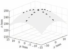
图9 双磁透镜成像测试数据拟合的弯曲像面Fig. 9 Curved image surfaces fitted by measuring data for double magnetic lens system
5 关于场曲的校正
从模拟和测试结果可知, 场曲近似与物点离轴距离的二次方成正比, 故大物面像管的场曲通常会比较大。理论上可采用球面光电阴极与球面栅网来减小场曲、像散, 同时采用曲面荧光屏与场曲作适当匹配来进一步减小场曲。这势必加大对像管设计与加工的精度要求, 在技术上实现起来有一定困难。采用场曲校正透镜可在一定程度上减小场曲, 但同时必须注意其可能引入的附加畸变等额外像差[。从实际应用的角度讲, 只需将场曲控制在一定范围内就可以满足需要。本文数值模拟和实验测试结果均表明双磁透镜成像场曲比单磁透镜成像场曲有明显改善。在此基础上, 深入开展多个磁透镜组合成像的研究, 可为进一步减小像管场曲提供新的思路。
6 结论
研制出大面积阴极短磁聚焦分幅变像管, 从透镜成像原理出发, 推导了成像倍率为2∶1时单磁透镜和双磁透镜成像场曲的近似公式, 提出了一种测量像管场曲的方法。同时利用Matlab编程模拟了不同离轴距离物点的最佳成像位置, 并通过实验进行了验证, 探讨了减小像管场曲的方法。数值模拟和实验测试结果表明, 单、双磁透镜下的最佳成像面均为旋转抛物面, 但双磁透镜成像场曲比单磁透镜有明显的改善。下一步工作将进行多个磁透镜组合成像场曲的研究, 并同时开展像差的校正工作。
The authors have declared that no competing interests exist.
作者已声明无竞争性利益关系。
参考文献
[1]
Deeney C, Douglas M R, Spielman R B, et al. Enhancement of X-ray power from a Z-pinch using nested-wire arrays[J]. 1998, 81( 22): 4883- 4886.
Nested-wire arrays on the 20-MA Z -pinch accelerator have produced x-ray powers up to 280{plus_minus}40 TW (a 40{percent} increase over a single array) and an x-ray pulse width of 4thinspthinspns. The short x-ray pulse widths are associated with the formation of tight (1-mm-diameter), uniform pinches at stagnation. Two-dimensional radiation magnetohydrodynamic calculations suggest that the inner array mitigates the growth of implosion instabilities thereby leading to smaller diameter pinches that radiate at higher power than single-wire arrays. {copyright} {ital 1998} {ital The American Physical Society }
[本文引用:1]
[2]
Ze F, Kauffman R L, Kilkenny J D, et al. A new multichannel soft X-ray framing camera for fusion experiments[J]. 1992, 63( 10): 5124- 5126.
Two dimensional, time resolved x-ray imaging is a principal technique used to study hot plasmas produced in laser heated targets. It can be used to study laser energy deposition within the irradiation spot, the spatial and temporal dependence of laser to x-ray conversion efficiency, electron transport and density profiles, mass ablation rates as well as x-ray driven implosions in inertial confinement fusion experiments. A new soft x-ray framing camera which will allow us to record two-dimensional images at different times almost simultaneously was successfully developed. It is a broad band diagnostic (100 eV less than or equal to delta(h(radical)) less than or equal to 400 eV) having three channels which can obtain x-ray images at four different times from laser driven targets. Its current configuration includes one 500 eV, one 1.0 keV, and one approximately 2.5 keV channels. The two low energy channels resulted from pairing transmission filters to grazing x-ray mirrors. Other channel options can be implemented easily to measure other x-ray energies. Four different striplines coated on a microchannel plate are gated at different times. Each strip records three different images taken nearly simultaneously, one image per channel. The result is twelve x-ray images on film, four images per channel taken at four different times, with a nominal resolution of approximately 100 ps per image. The diagnostics' spatial resolution is approximately 10 microns. This new instrument was already fielded during x-ray conversion experiments, using both low and high Z targets driven by 1ns-2ns, 'flat top' laser pulses. The details of the instrument design and sample results from conversion experiments are shown.
[本文引用:1]
[3]
Shan B, Yanagidaira T, Shimoda K, et al. Quantitative measurement of X-ray images with a gated microchannel plate system in a Z-pinch plasma experiment[J]. 1999, 70( 3): 1688- 1693.
A multiframe, gated pinhole system capable of quantitative acquisition for pulsed soft x rays is described and tested. The system based on a gated microchannel plate (MCP) is employed to observe the evolution ofz-pinch plasma in a plasma focus facility with a time resolution of 65220 ps. The quantitative relationship between x-ray source intensity and the recorded images has been investigated. To make a quantitative measurement, the phosphor screen current was measured to calculate the total electrons output from the MCP, which is proportional to both the incident x-ray intensity and the intensity of the recorded images. Furthermore, by taking into account the pinhole geometry, MCP gain and system spectral response, a quantitative calibration of the x-ray images has been established. We have employed the system to observe the plasma evolution in a plasma focus facility. An order of651016photons/(s66mm2mrad2)soft x-ray emission within 6–14 03 was observed in a neon puffed experiment with time resolved four successive frames.
[本文引用:1]
[4]
Cai H Z, Liu J Y, Peng X, et al. Non-gain microchannel plate gated framing camera[J]. 2011, 82( 5): 056102.
An x-ray framing camera using a non-gain microchannel plate (MCP) is reported in this article. The advantage of the non-gain MCP is the less transit time spread. The non-gain MCP gated framing camera has four microstrip line cathodes with 6 mm in width. The time domain reflectometry curves of the four microstrip lines are measured, which show that the characteristic impedance of each microstrip line is about 17 惟. While the photocathode is driven by the gating electrical pulse with width of 125 ps and amplitude of -1.48 kV with -400 V bias, the measured exposure time of this camera is about 72 ps.
[本文引用:1]
[5]
Cai Houzhi, Liu Jinyuan, Peng Xiang, et al. Design of an X-ray framing camera with wide microstrip line[J]. Chinese J Lasers, 2012, 39( 1): 0117001.蔡厚智, 刘进元, 彭翔, 等. 宽微带X射线分幅相机的研制[J]. 2012, 39( 1): 0117001.
研制了应用于平焦场光栅谱仪系统的宽微带X射线分幅相机,微通道板(MCP)微带阴极的宽度为20 mm,由四路选通脉冲同时驱动。分幅相机采用模块化设计,由气室、MCP变像管、电控系统、光学CCD记录系统和内嵌式计算机组成,内嵌PC104模块实现相机的远程控制。对相机进行联调实验,测得该相机的时间分辨率为71 ps,空间分辨率为20 lp/mm,垂直于选通脉冲传播方向的微带均匀性为1.51,平行于选通脉冲传播方向的微带均匀性为5.11。
[本文引用:1]
[6]
Koga M, Fujiwara T, Sakaiya T, et al. Measurement of heating laser injection time to imploded core plasma by using X-ray framing camera[J]. Review of Scientific Instruments, 2008, 79(10): 10E909.
[本文引用:1]
[7]
Bradley D K, Bell P M, Land en O L. Development and characterization of a pair of 30-40 ps X-ray framing cameras[J]. 1995, 66( 1): 716- 718.
We have constructed two slightly different high‐speed framing cameras for use on NOVA and the OMEGA Upgrade. Both units are based on the gating of a microchannel plate, with one detector having a pore length to diameter ratio half that of the other. We will discuss the factors limiting the temporal resolution of each detector and will compare the results of modeling with gate width measurements taken using a short‐pulse laser. We will also compare time‐resolved x‐ray images recorded using one of these devices with data from an older (6590 ps resolution) detector.
[本文引用:1]
[8]
Oertel J A, Archuleta T N, Schrank L S. The large format X-ray imager[J]. 2001, 72( 1): 701- 704.
We introduce a new Large Format X-ray Imaging Camera (LFC) for the Los Alamos National Laboratory (LANL) Inertial Confinement Fusion/Radiation Physics (ICF/RP) program. This instrument is intended as a prototype for use at the National Ignition Facility (NIF), but is capable of operating at LANL’s Trident and the University of Rochester’s OMEGA laser systems. The LFC is based upon similar x-ray camera architecture and is currently in the final design stages. It is constructed around a mosaic of 3 large (35×105 mm2) microchannel plate (MCP) detectors, primarily to give a larger field of view, but also for greater temporal coverage and higher magnification while maintaining spatial resolution. The camera is designed to have 30 data channels, six 13-mm-wide microstrips, continuous temporal coverage of 4.2 ns, adjustable electrical gate width, and variable gain on each microstrip and magnifications up to 20×. In the process of designing the LFC we scrutinized every element of the gated x-ray imaging process and designed optimization experiments for many of these elements. From the results of two of these experiments, improvements were made in impedance matching to MCPs and, in another, optimization of phosphor on faceplates.
[本文引用:1]
[9]
Cai H Z, Liu J Y, Peng X, et al. Large-format microchannel plate gated framing camera[J]. 2012, 677: 14- 17.
An X-ray framing camera using a large-format microchannel plate (MCP) is reported. The diameter of the MCP is 106mm and the width of each microstrip line cathode deposited on the MCP is 12mm. The temporal record length of the camera is about 3ns. The photocathode is driven by a gating electrical pulse having a width of 175ps and an amplitude of 612.5kV plus 61300V bias, while the exposure time is about 69ps. Finally the gain uniformity of the microstrip line photocathode is measured, showing that there is a 8.9× drop in gain along the pulse propagation direction, whereas the variations in the gain transverse to the pulse propagation direction are within 16.7%.
[本文引用:1]
[10]
Hilsabeck T J, Hares J D, Kilkenny J D, et al. Pulse-dilation enhanced gated optical imager with 5 ps resolution[J]. Review of Scientific Instruments, 2010, 81(10): 10E317.
[本文引用:1]
[11]
Bai Yanli, Long Jinghua, Cai Houzhi, et al. Influence of double magnetic lenses on performance of pulse-dilation framing tube[J]. Laser & Optoelectronics Progress, 2016, 53( 1): 013201.白雁力, 龙井华, 蔡厚智, 等. 双磁透镜对时间展宽分幅变像管性能的影响[J]. 2016, 53( 1): 013201.
采用双磁透镜设计时间展宽分幅变像管,对其空间分辨特性进行模拟和测试。采用2#分辨率板测试像管空间分辨率,以及大面积阴极测试像管在离轴位置的空间分辨能力。测试结果表明,双磁透镜像管的空间分辨率为74 μm;在图像缩小1 倍时,能有效分辨阴极距离中心轴位置30 mm 的信息。像管的空间分辨率和在阴极离轴位置的分辨能力都优于单磁透镜像管。因此,双磁透镜能有效提高时间展宽分幅变像管的空间分辨特性。
[本文引用:1]
[12]
Bai Y L, Long J H, Liu J Y, et al. Demonstration of 11 ps exposure time of a framing camera using pulse-dilation technology and a magnetic lens[J]. 2015, 54( 12): 124103.
A framing camera with high temporal and spatial resolution is demonstrated using pulse-dilation technology and a magnetic lens. The magnetic field of the magnetic lens is simulated using LORENTZ-3EM software, and the magnetic field distribution on-axis is similar to a Gaussian function. The temporal and spatial resolutions of the instrument are measured using light at the wavelength of 26602nm from a frequency tripled femtosecond laser. The measured exposure time of this camera is 0011 ps, and the spatial resolution is better than 100 μm.
[本文引用:1]
[13]
Yin Ming, Sun Xiaojun. A study of thick lenses of e-beam exposure system with a large object surface[J]. Acta Photonica Sinica, 2004, 33( 4): 509- 512.尹明, 孙晓军. 电子束曝光机大物面强磁透镜的研究[J]. 2004, 33( 4): 509- 512.
以SDS-3电子束曝光机的聚焦透镜系统为基础,在0.005弧度半张角,3×10-5的高压纹波,50 mm的像距,30×30 mm扫描场的条件下,研究了电磁透镜成像的笛卡尔坐标系中的近轴轨迹方程,给出了相应的计算初值条件和实例.讨论了电子束曝光机聚焦透镜系统中的球差、彗差、像散、场曲和畸变等电子光学特性的确定以及系统像质评定的问题.
[本文引用:1]
[14]
Du Bingchu, Wang Jianru. Electron optics[M]. Beijing: Tsinghua University Press, 2002: 188- 190.杜秉初, 汪健如. 电子光学[M]. 北京: 清华大学出版社, 2002: 188- 190.
[本文引用:2]
[15]
Liao Yubo, Long Jinghua, Cai Houzhi, et al. Numerically simulated static spatial resolution of framing image converter using magnetic focusing via Matlab[J]. Laser & Optoelectronics Progress, 2016, 53( 1): 012301.廖昱博, 龙井华, 蔡厚智, 等. 磁聚焦分幅变像管静态空间分辨率的Matlab模拟研究[J]. 2016, 53( 1): 012301.
基于脉冲展宽分幅技术,设计研制了一种短磁聚焦变像管。采用磁标位分析法求解磁场分布,通过对电子轨迹追迹的方法并结合Matlab编程对像管的静态空间分辨率进行了模拟计算。在阴栅电势差为3kV,成像倍率为1:1,成像激励为450安匝的条件下,得出在阴极中心、离轴5mm和离轴10mm处的空间分辨率分别为17,8.6和5.3lp/mm。考查了阴栅电势差和磁透镜空气隙缝宽度等因素对空间分辨率的影响,并借助像差理论予以解释。该程序模型占用内存小、执行速度快,可为变像管的设计和分析提供更为便捷的途径。
[本文引用:2]
[16]
Hui Dand an, Tian Jinshou, Lu Yu, et al. Streak tube with large work area and small size used in lidar detection system[J]. Acta Optica Sinica, 2015, 35( 12): 1232001.惠丹丹, 田进寿, 卢裕, 等. 用于激光雷达的大探测面积超小型条纹管[J]. 2015, 35( 12): 1232001.
利用三维电磁仿真软件CST 模拟设计了一款小型电聚焦条纹管,在模拟中采用了正交实验法来确定条纹管各电极间距离及各电极电压。同时,根据条纹管像差定义对其像质进行了全面的理论分析和评价。优化设计的条纹管阴极有效工作面积直径大于28 mm,物理时间分辨率优于30 ps,边缘静态空间分辨率大于20 lp/mm,条纹管放大倍率为1.07,总管长仅为100 mm,管外围直径为50 mm。满足航天、空间探测以及海洋执法等应用领域非扫描式激光雷达技术对大探测面积、超小型条纹变像管的应用需求。
[本文引用:1]
[17]
Xia Shanhong, Zhu Xieqing. Design of extremely low field curvature combined focusing and deflection systems[J]. Acta Electronica Sinica, 1991, 19( 1): 65- 71.夏善红, 朱协卿. 一种极低场曲复合聚焦偏转系统的设计[J]. 1991, 19( 1): 65- 71.
[本文引用:1]
1
1998
0.0
0.0
1
1992
0.0
0.0
1
1999
0.0
0.0
1
2011
0.0
0.0
1
2012
0.0
0.0
1
2008
0.0
0.0
1
1995
0.0
0.0
1
2001
0.0
0.0
1
2012
0.0
0.0
1
2010
0.0
0.0
... Hilsabeck等[10]将脉冲展宽技术(PDT)和MCP行波选通技术相结合,成功研制了时间展宽分幅相机 ...
1
2016
0.0
0.0
... 在此基础上改进磁透镜结构,在电子光学设计中引入一个短磁透镜替代长磁聚焦,研制了短磁聚焦时间展宽分幅像管[11],其时间分辨率达到11 ps,动态空间分辨率优于10 lp/mm(100 μm)[12] ...
1
2015
0.0
0.0
... 在此基础上改进磁透镜结构,在电子光学设计中引入一个短磁透镜替代长磁聚焦,研制了短磁聚焦时间展宽分幅像管[11],其时间分辨率达到11 ps,动态空间分辨率优于10 lp/mm(100 μm)[12] ...
1
2004
0.0
0.0
... 2 像管场曲的理论分析电子束的场曲是由远轴区与近轴区的聚焦能力不同造成的[13] ...
2
2002
0.0
0.0
... 对于短磁透镜,焦距与励磁电流之间近似满足[14] ...
... 当磁透镜缝隙较小时,轴上磁感应强度分布为[14] ...
2
2016
0.0
0.0
... 由此,再根据磁场的幂级数展开式,可得轴外的磁场分布[15] ...
... 光电子发射条件、电子轨迹的分析参照文献[ 15] ...
1
2015
0.0
0.0
1
1991
0.0
0.0
... 采用场曲校正透镜可在一定程度上减小场曲,但同时必须注意其可能引入的附加畸变等额外像差[17] ...


 1万+
1万+


 被折叠的 条评论
为什么被折叠?
被折叠的 条评论
为什么被折叠?
 到【灌水乐园】发言


