


 本文探讨了相控阵雷达的工作原理,通过天线图和实际信号仿真实验展示了信号的合成与天线方向增益特性。在实验中,详细计算了相邻单元的相位差和移相器的最佳相位,并使用Matlab进行信号仿真,呈现了不同单元的信号以及总和信号的时域表现。此外,还分析了不同方向的天线图,包括法线和45度方向的增益特性。
一项新的雷达原理作业,依旧是拿word写的,懒得转LaTeX了,截图凑合看吧,需要word的私信,有问题欢迎评论区留言。
一、 问题提出

二、问题解决
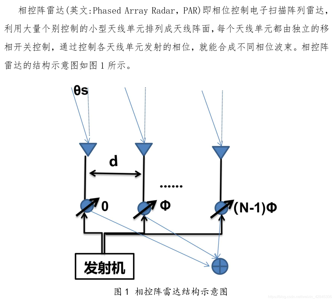
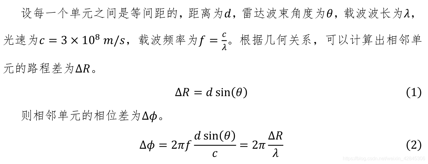
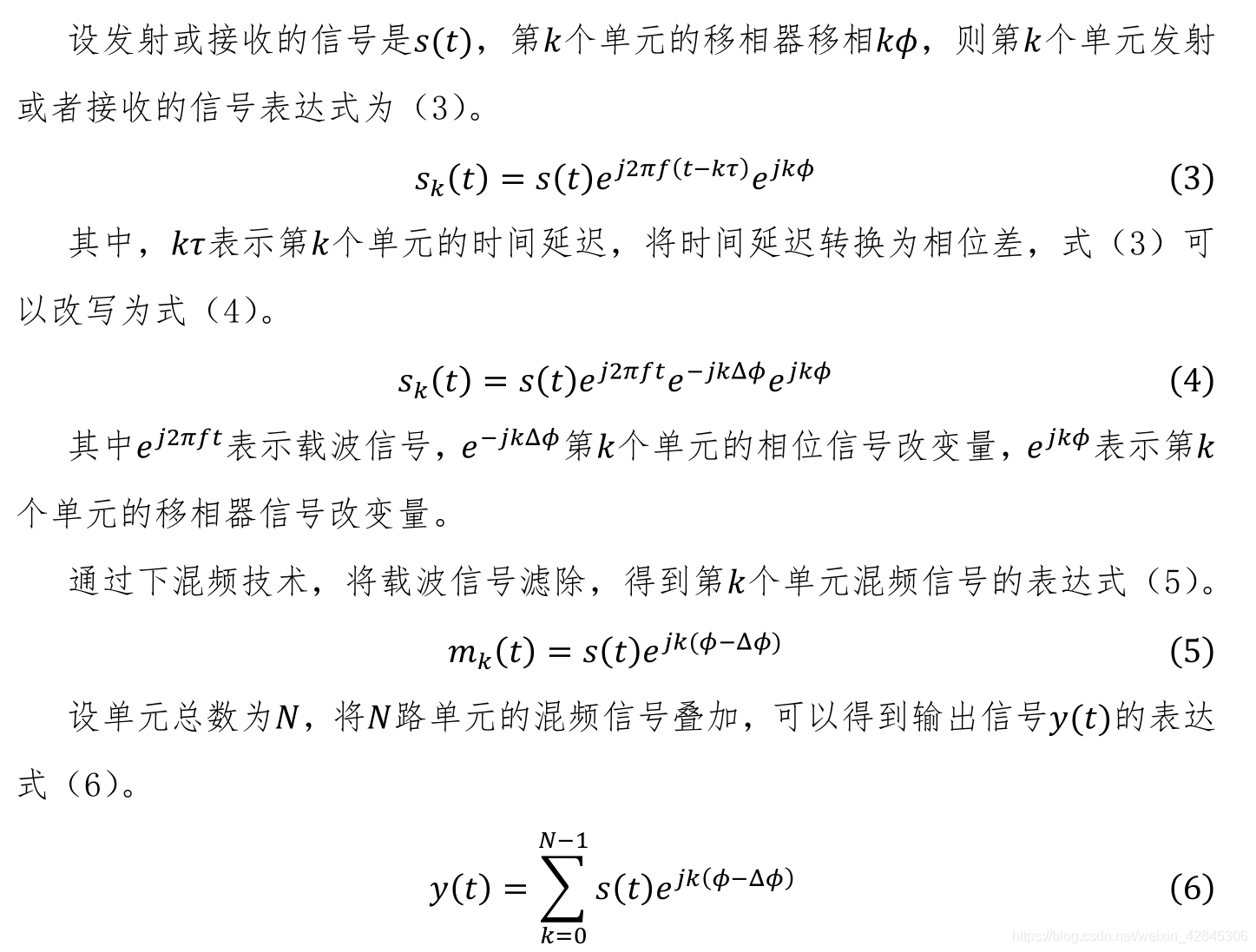
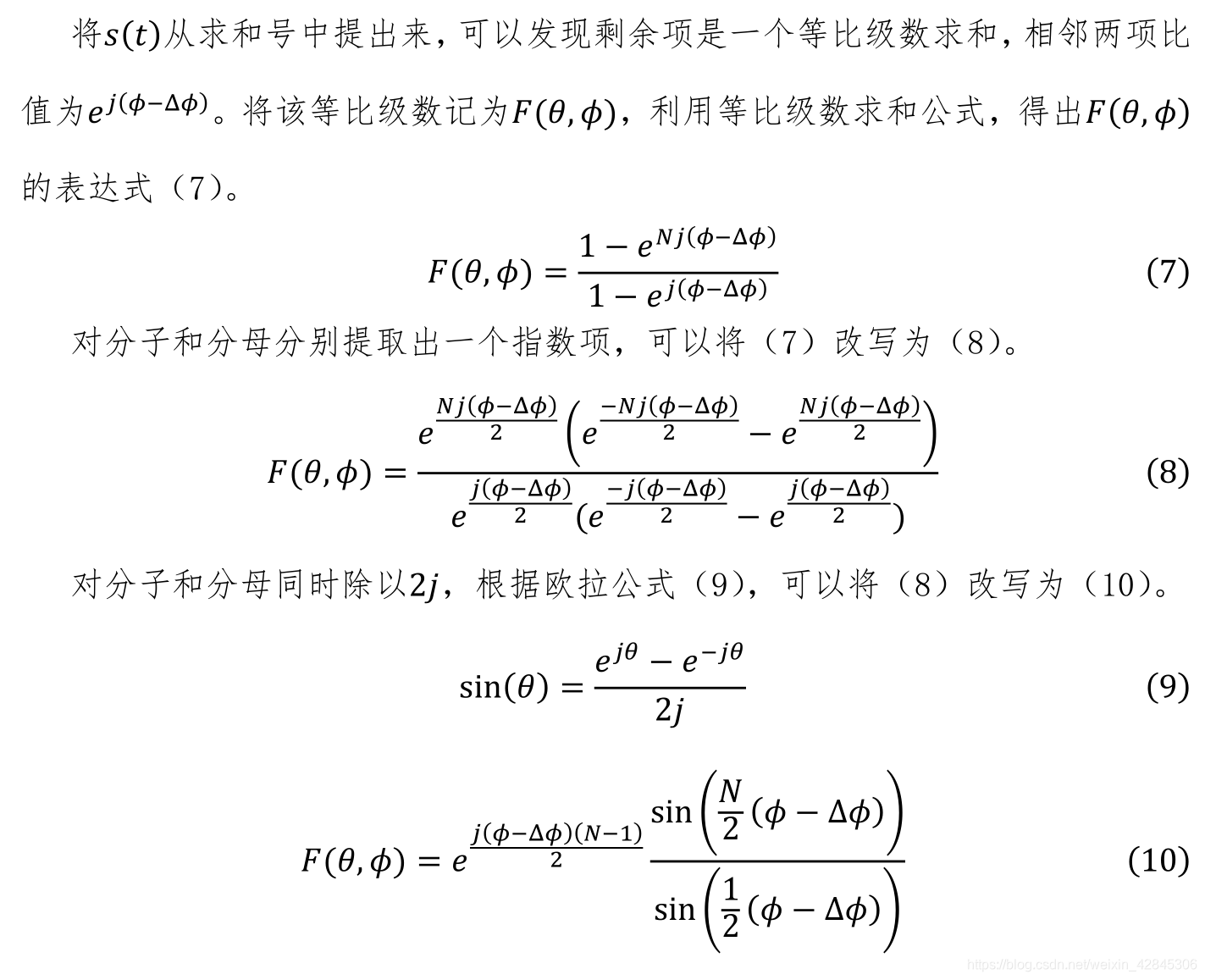
1.相控阵雷达原理:
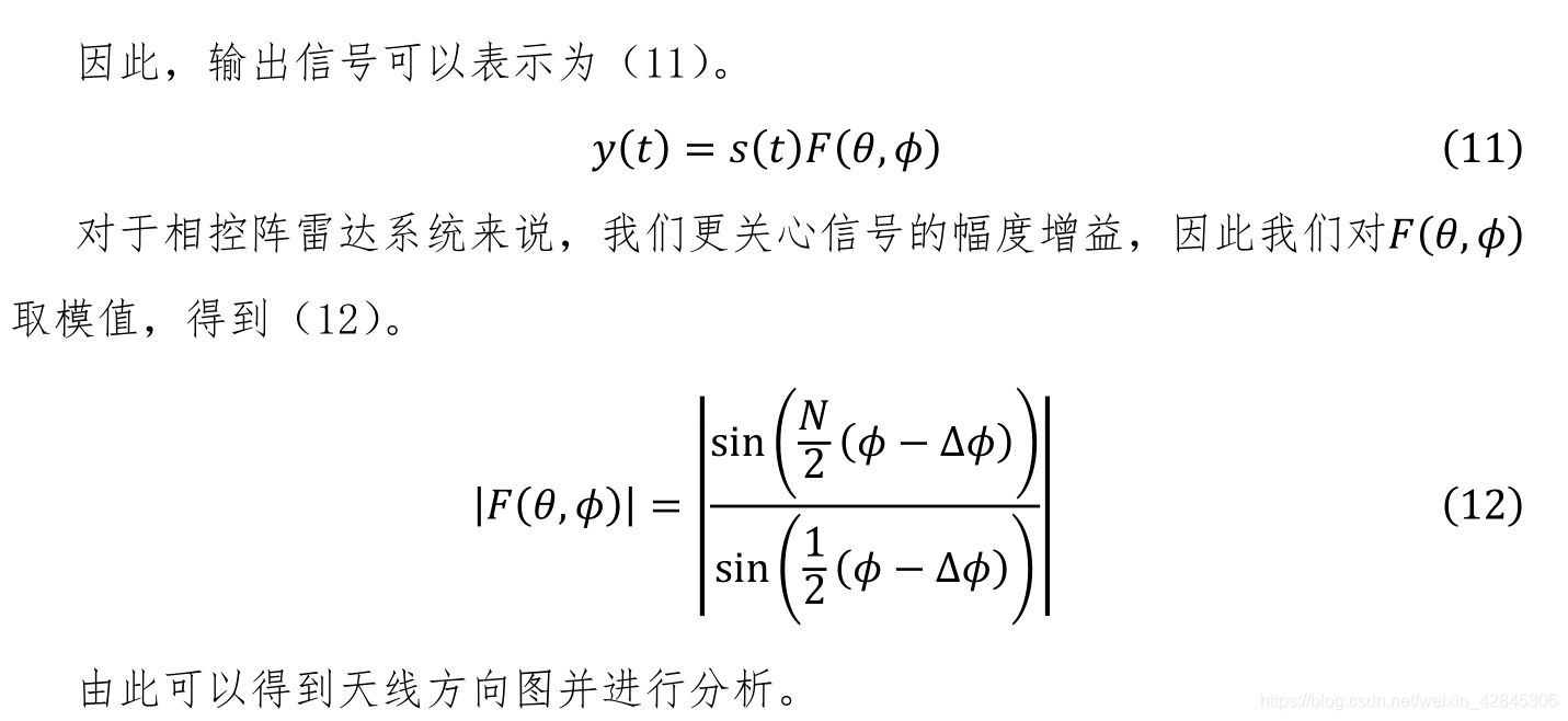
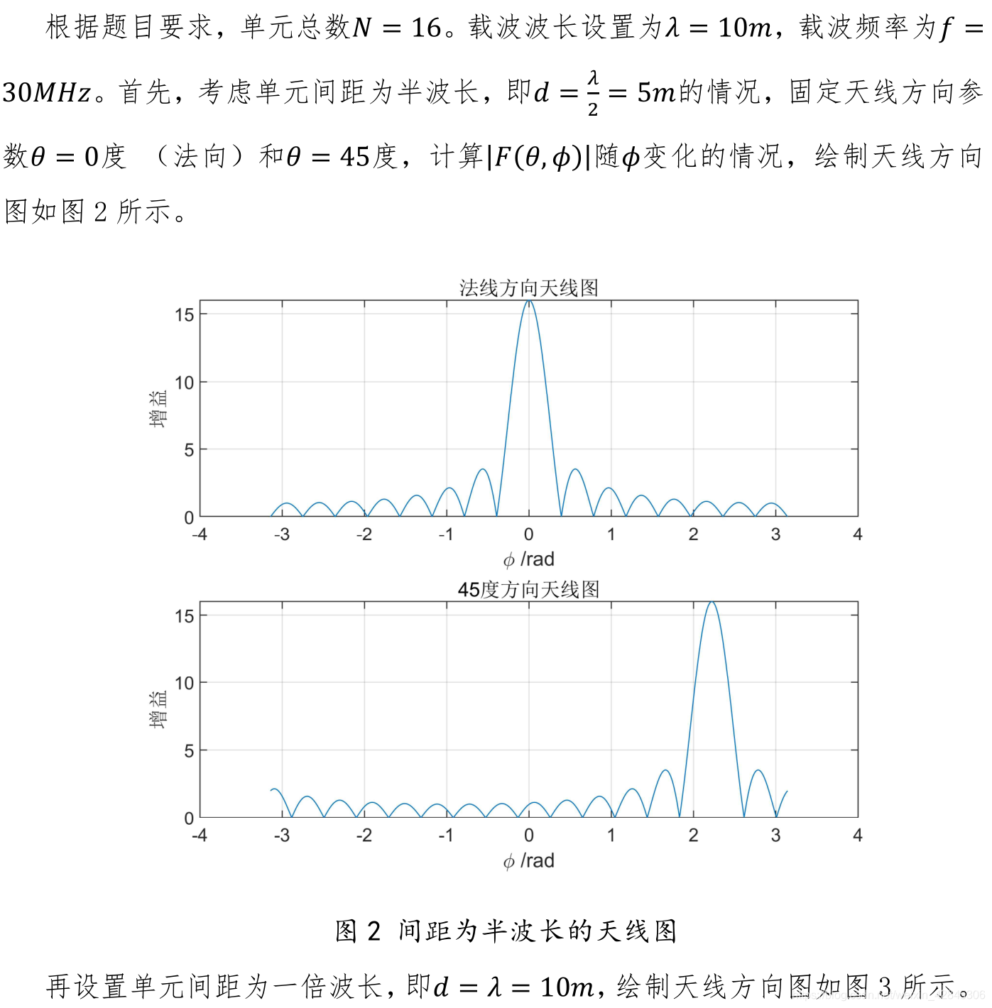
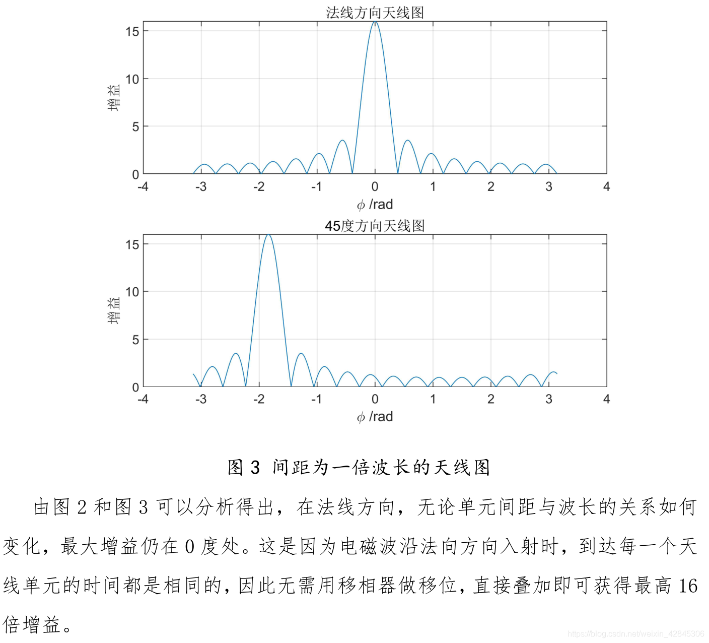
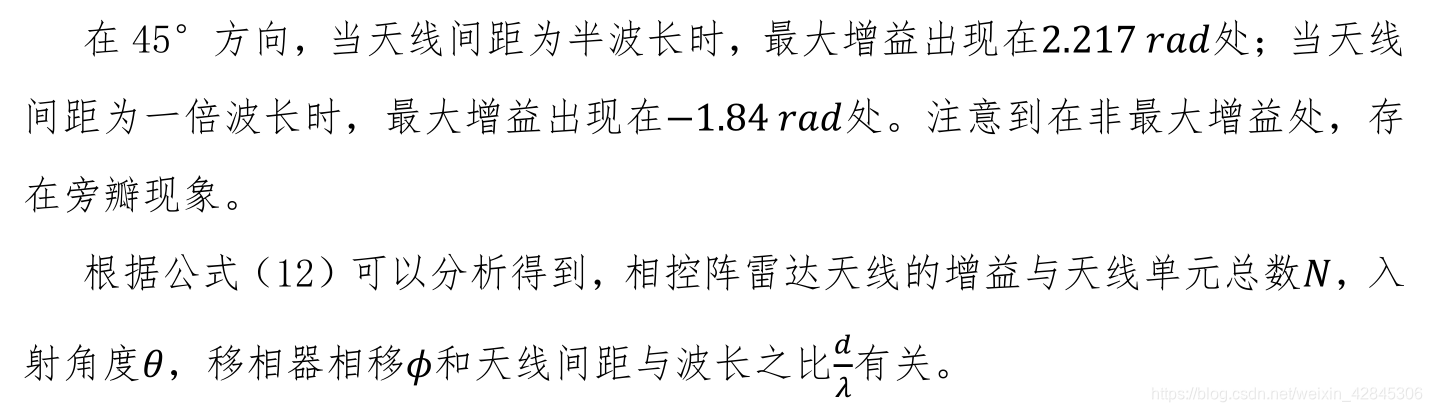
2.天线图仿真实验:
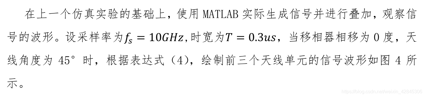
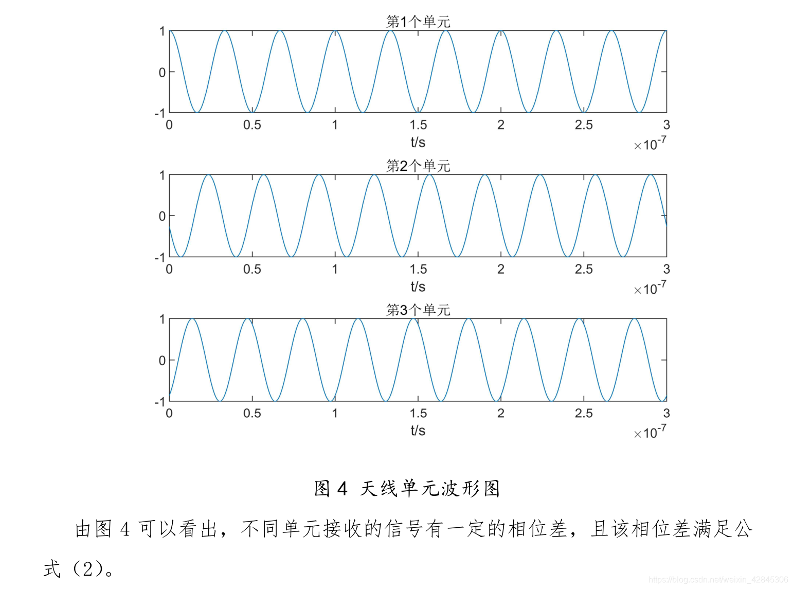
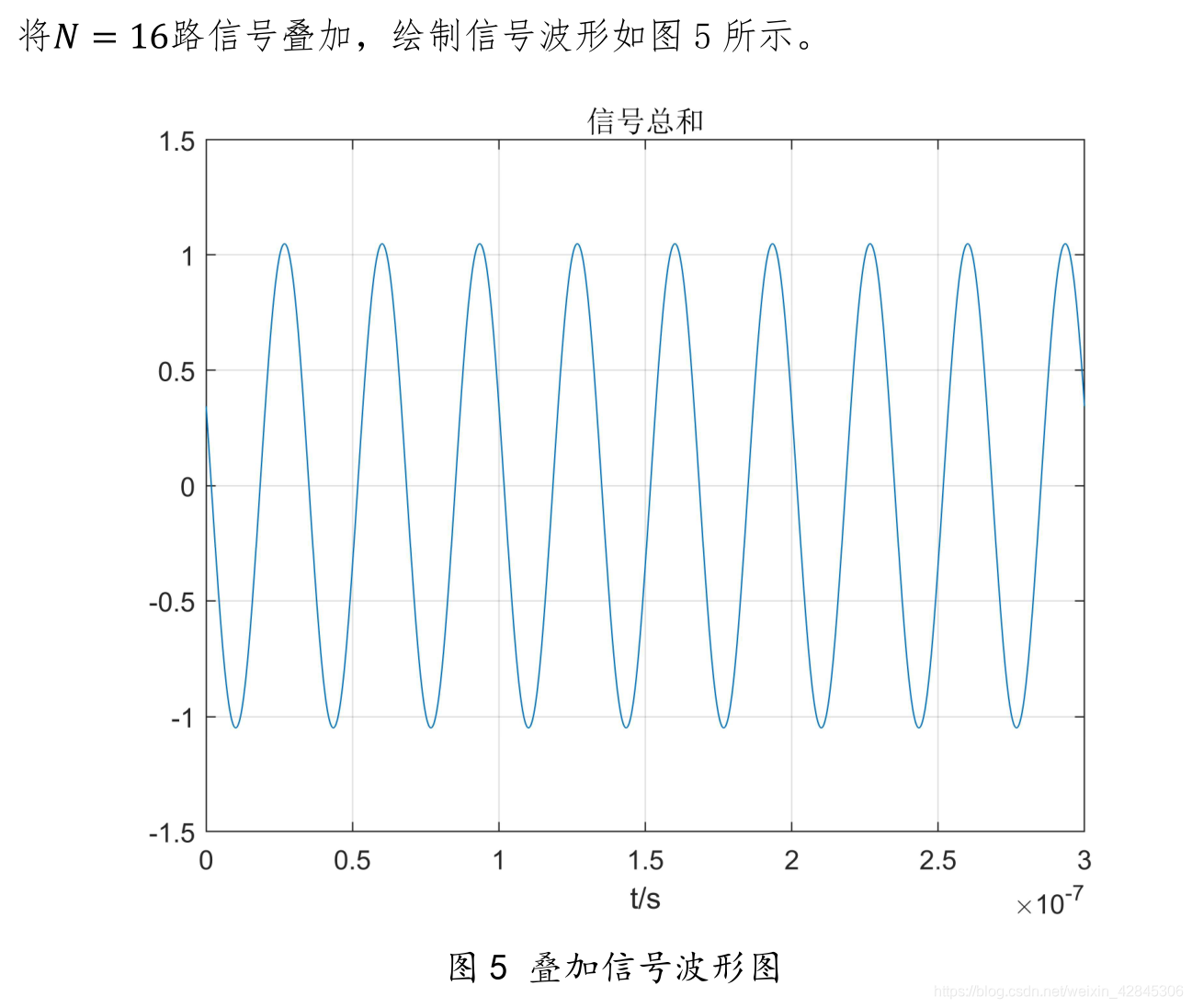
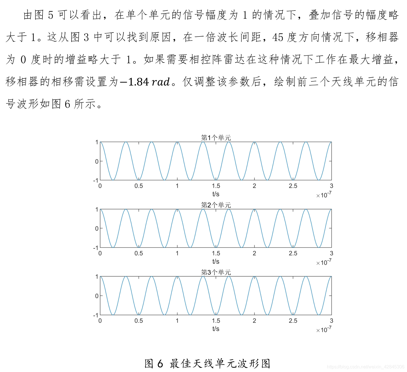
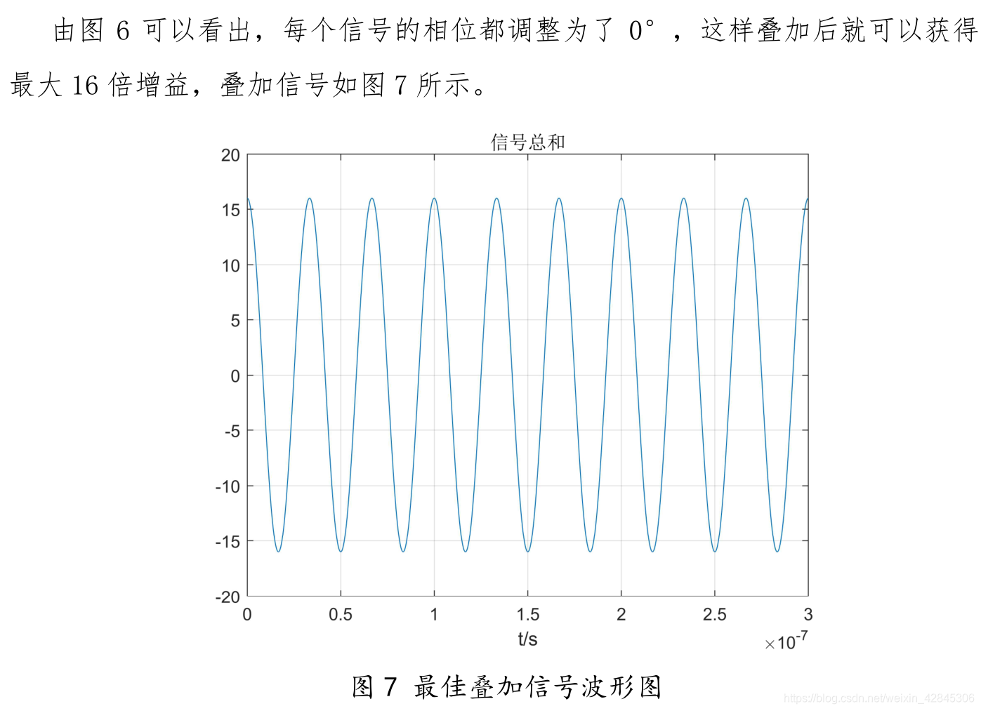
3.实际信号仿真实验:
三、心得感悟
附代码:
theta=45*pi/180;%波束角度,以度算
d=10;%阵列间距,m
N=16;%阵元总数
lambda=10;%信号波长,m
c=3e8;%光速
f=c/lambda;%信号频率
dR=d.*sin(theta);%相邻单元路程差
dphi=2*pi.*dR./lambda;%相邻单元相位差
% phi=0;%每个的移相器的相位
phi=-1.84;%最佳移相器相位

T=3e-7;%时宽,秒
fs=1e10;%采样频率
n=round(T.*fs);%采样点数
t=linspace(0,T,n);%时间刻度
s=@(t,k) exp(1j*2*pi*f.*t).*exp(-1j.*k.*dphi).*exp(1j.*k.*phi);%每个单元的信号

figure(1)
subplot(311)
plot(t,real(s(t,0)))
xlabel("t/s")
title("第1个单元")
subplot(312)
plot(t,real(s(t,1)))
xlabel("t/s")
title("第2个单元")
subplot(313)
plot(t,real(s(t,2)))
xlabel("t/s")
title("第3个单元")

figure(2)
sum_s=zeros(1,length(t));
for k=0:N-1
    sum_s=sum_s+s(t,k);%每个信号累加
end
plot(t,real(sum_s))
xlabel("t/s")
title("信号总和")
grid on

figure(3)
F=@(theta,phi) sin(N*(phi-(2*pi*d*sin(theta)/lambda))/2)./sin((phi-(2*pi*d*sin(theta)/lambda))/2);%方向增益
test_phi=linspace(-pi,pi,1000);%移相器相位刻度
subplot(211)
plot(test_phi,abs(F(0,test_phi)))
grid on
xlabel("\phi /rad")
ylabel("增益")
title("法线方向天线图")
subplot(212)
plot(test_phi,abs(F(pi/4,test_phi)))
grid on
xlabel("\phi /rad")
ylabel("增益")
title("45度方向天线图")

d=5;%半波长
figure(4)
F=@(theta,phi) sin(N*(phi-(2*pi*d*sin(theta)/lambda))/2)./sin((phi-(2*pi*d*sin(theta)/lambda))/2);%方向增益
test_phi=linspace(-pi,pi,1000);%移相器相位刻度
subplot(211)
plot(test_phi,abs(F(0,test_phi)))
grid on
xlabel("\phi /rad")
ylabel("增益")
title("法线方向天线图")
subplot(212)
plot(test_phi,abs(F(pi/4,test_phi)))
grid on
xlabel("\phi /rad")
ylabel("增益")
title("45度方向天线图")
留赞走
没想到这篇文章这么火,很多人向我要word版,总是发邮件感觉比较麻烦,干脆直接把它上传吧
下载链接


 896
896

 被折叠的 条评论
为什么被折叠?
被折叠的 条评论
为什么被折叠?
 到【灌水乐园】发言


