


拓扑

0、错误代码40解决方法
原因:路由器型号为AR2220,因为virtual-box的原因打不开
解决方法:AR2220替换为Router,使用copper线连接图中指定的接口、


1、子网划分
利用VLSM(变长子网掩码)划分192.168.1.0~192.168.2.0/24,使IP地址最为节省的方式分配给总部设备
VLSM(变长子网掩码)解释:
192.168.1.0/24,网络位24,主机位8
其中可用主机位:2^n-2 = 2^8-2 = 254 ;2=网络地址+广播地址
3个部门,每个部门20个人
2^n-2 >= 20,n=5,主机位5位
每个子网2^5 = 每个子网32个主机数,其中可用主机数30个
子网1:192.168.1.0/27 ~192.168.1.31/27
子网2:192.168.1.32/27 ~192.168.1.63/27
子网3:192.168.1.64/27 ~192.168.1.95/27
主根-出口路由器,2个主机位
2^n-2 >= 2,n=2,主机位2位
每个子网2^2 = 每个子网4个主机数,其中可用主机数2个
子网6:192.168.1.96/30~192.168.1.99/30
备根-出口路由器,2个主机位
2^n-2 >= 2,n=2,主机位2位
每个子网2^2 = 每个子网4个主机数,其中可用主机数2个
子网5:192.168.1.100/30~192.168.1.103/30
主根-WEB服务器,2个主机位
2^n-2 >= 2,n=2,主机位2位
每个子网2^2 = 每个子网4个主机数,其中可用主机数2个
子网4:192.168.1.104/30~192.168.1.107/30
2、DHCP协议
DHCP=动态主机配置协议
C/S架构=clinet/server架构,通过dhcp server 分配地址给 client
先将三台主机的IP地址改为DHCP方式获取
3、企业架构
3核心层
2汇聚层
1接入层
4、配置接入层
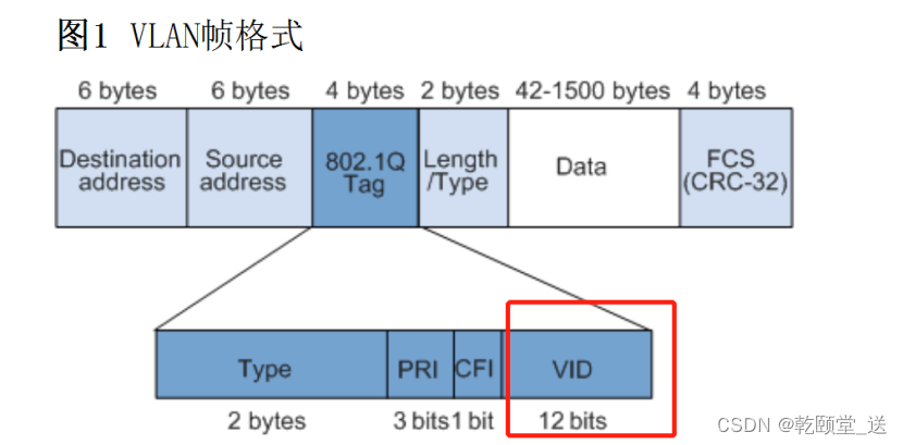
VLAN = virtual local area network =划分局域网的协议

VLAN ID 的范围 =VID 12bit = 2^12 = 4096 = 0 ~ 4095,0和4095不能分配
VLAN帧格式
配置ACC1-S1
配置VLAN
ACC1-S1
sys
sysname ACC1
创建一种vlan
vlan 10
创建多个vlan
vlan batch xx xx xx
配置接口
int e0/0/3
port link-type access --- 配置接口类型
port default vlan 10 --- 修改PVID(port vlan id)
vlan-list=允许通过vlan的列表
目前E0/0/1和E0/0/2没有vlan-list
int e0/0/1
port link-type trunk --- 配置接口类型
port trunk allow-pass vlan 10 ---增加vlan-list
int e0/0/2
port link-type trunk
port trunk allow-pass vlan 10
查询接口变化(E0/0/3)
[ACC1]display port vlan active ---- 查询活跃的vlan接口
T=TAG U=UNTAG
-------------------------------------------------------------------------------
Port Link Type PVID VLAN List
-------------------------------------------------------------------------------
Eth0/0/1 trunk 1 U: 1
T: 10,vlan-list=允许vlan id 10的数据帧通过
Eth0/0/2 trunk 1 U: 1
T: 10
Eth0/0/3 access 10,原始数据帧进入的时候封装的tag U: 10,剥掉10的vlan id标签
配置ACC2-S2、ACC3-S3配置相似,自行配置
快捷查询接口(以ACC1举例)
[ACC1]display current-configuration interface 查询全局配置中所有接口的配置,空格翻页,回车换行
#
interface Vlanif1
#
interface MEth0/0/1
#
interface Ethernet0/0/1
port link-type trunk
port trunk allow-pass vlan 10
#
interface Ethernet0/0/2
port link-type trunk
port trunk allow-pass vlan 10
#
interface Ethernet0/0/3
port link-type access
port default vlan 10
配置MSTP
STP=防环

图中为三台交换机和两台PC进行连接
场景:左侧PC需要和右侧PC通信(发送了ARP请求)
ARP报文
ARP请求=广播
ARP应答=单播
MAC地址多少个bit
举例:00-50-56-C0-00-08(12个16进制,48个2进制/bit)
1个16进制 = 4个2进制
如何区分广播帧、单播帧、组播帧
看数据帧的MAC地址的第8个bit
第8个bit = 0 = 单播
第8个bit = 1 = 组播
48个bit全1 = 广播

f=1111,48个bit全为1

第8个bit=0,单播

第2个16进制=1,转为2进制=0001
第8个bit=1,组播
现在回到最开始的点---STP

交换机的转发原理

泛洪:
除接收端口外,所有的端口都做转发
当交换机收到(BUM帧)广播帧/未知帧/组播帧,交换机将此类报文进行泛洪
转发:
当交换机收到单播帧的时候,按照MAC地址表进行转发
丢弃:
当交换机收到与MAC地址表错误的映射关系时,进行丢弃
MAC地址表

将物理接口和接口入方向的设备MAC地址进行映射
收到数据帧(因为有目的MAC地址),交换机就可以直接查表转发
<ACC1>display mac-address ----查询设备的MAC地址表
MAC address table of slot 0:
-------------------------------------------------------------------------------
MAC Address VLAN/ PEVLAN CEVLAN Port Type LSP/LSR-ID
VSI/SI MAC-Tunnel
-------------------------------------------------------------------------------
5489-9872-04e2 10 - - Eth0/0/3 dynamic 0/-
-------------------------------------------------------------------------------
Total matching items on slot 0 displayed = 1
再次回到最开始的点---STP

问题1:
当左侧PC发送广播帧到接入交换机时,交换机根据转发原理进行泛洪
交换机进行泛红后,所有的接口都做转发,形成广播风暴
问题2:
由于MAC地址表会进行刷新,所以数据帧绕一圈之后,就会与别的接口建立映射关系,导致MAC地址表漂移/震荡/混乱
STP角色选举
选举一个根桥,看的是BID
BID = 桥优先级+MAC地址,越小越优先
桥优先级范围:0~65535,默认是32768,步长是4096
ACC1举例
<ACC1>display stp
-------[CIST Global Info][Mode MSTP,默认模式MSTP]-------
CIST Bridge :32768.4c1f-cccd-31cd ---BID
Config Times :Hello 2s MaxAge 20s FwDly 15s MaxHop 20
Active Times :Hello 2s MaxAge 20s FwDly 15s MaxHop 20
CIST Root/ERPC :32768.4c1f-cc1a-204d / 200000
CIST RegRoot/IRPC :32768.4c1f-cccd-31cd / 0
根桥选举完毕之后
选举根端口,非根桥距离根桥最近的端口
PID=端口优先级+端口号
端口优先级范围:0~240,默认是128,步长16

选举指定端口
其中根桥的每个接口都是指定端口
非根桥继续根据四个比较原则选举指定端口
选举阻塞端口
因为STP的原理就是选举一个端口进行阻塞然后破环
非根桥中有且只有一个根端口
非根桥之间有且只有一个指定端口
非根桥中的所有端口,没选为指定端口和根端口则为阻塞的端口
端口角色


RSTP的改进

其中RSTP增加了端口角色
Alternate:根端口的备份端口
Backup:指定端口的备份端口
改进了端口状态

增加了端口种类----边缘端口
一般作为连接主机端口的角色
如果主机频繁的开机关机或者上下班高峰期,STP就会频繁的进行端口状态的计算,导致负载过高
就定义了边缘端口,不管怎么说,边缘端口不参与STP的状态计算,永远都是forwarding
MSTP
由于生成树只有一颗,所以会导致次优路径或没有负载分担的问题


此时,通过多生成树MSTP,在域中创建多颗生成树,每颗阻塞情况是不同的

MSTP的配置
为了讲而讲,其实图中完全没必要做MSTP
stp region-configuration ---创建mstp域
region-name test ---改名
instance 1 vlan 10 to 13 ---实例1
instance 2 vlan 20 to 23 ---实例2
instance 3 vlan 30 to 33 ---实例3
active region-configuration ---配置生效(最重要,否则配置无效)
以上配置在总部每一台交换机都配置
额外配置
在主根和备根的交换机定义谁是主根,谁是备根
主根配置
vlan batch 10 20 30
stp instance 1 root primary ---在实例x里是主根
stp instance 2 root primary
stp instance 3 root primary
备根配置
vlan batch 10 20 30
stp instance 1 root secondary ---在实例x里是备根
stp instance 2 root secondary
stp instance 3 root secondary
ACC1举例,进行查询
[ACC1-mst-region]dis stp brief ---查询stp端口角色、状态
MSTID Port Role STP State Protection
0 Ethernet0/0/1 ROOT FORWARDING NONE
0 Ethernet0/0/2 ALTE DISCARDING NONE
0 Ethernet0/0/3 DESI FORWARDING NONE
1 Ethernet0/0/1 DESI FORWARDING NONE
1 Ethernet0/0/2 DESI FORWARDING NONE
1 Ethernet0/0/3 DESI FORWARDING NONE
5、配置汇聚层
配置VLAN
主根配置VLAN,刚刚VLAN 10 20 30在MSTP中已经创建
sys
sys AGG-S1
vlan batch 97 101 ---为连接WEB服务器和出口路由器的VLAN
主根划分端口
interface GigabitEthernet0/0/1
port link-type trunk
port trunk allow-pass vlan 10
#
interface GigabitEthernet0/0/2
port link-type trunk
port trunk allow-pass vlan 20
#
interface GigabitEthernet0/0/3
port link-type trunk
port trunk allow-pass vlan 30
#
interface GigabitEthernet0/0/6
port link-type access
port default vlan 101
#
interface GigabitEthernet0/0/7
port link-type access
port default vlan 97
-----------------------------------------------
备根配置VLAN,刚刚VLAN 10 20 30在MSTP中已经创建
sys
sys AGG-S2
vlan batch 105 ---为出口路由器的VLAN
备根划分端口
interface GigabitEthernet0/0/1
port link-type trunk
port trunk allow-pass vlan 10
#
interface GigabitEthernet0/0/2
port link-type trunk
port trunk allow-pass vlan 20
#
interface GigabitEthernet0/0/3
port link-type trunk
port trunk allow-pass vlan 30
#
interface GigabitEthernet0/0/6
port link-type access
port default vlan 105
配置链路聚合
产生背景:
本来的端口速率为5M,如果没有链路聚合,则花钱更新设备
有链路聚合后,就会把多个端口组合起来,5M x n 的速率
而且还可以增加可靠性
分类:
手工模式链路聚合和LACP

主根配置
interface Eth-Trunk 12 --- 创建聚合链路接口
trunkport GigabitEthernet 0/0/4 0/0/5 ---批量加入成员端口
port link-type trunk
port trunk allow-pass vlan all ---允许所有vlan通过
只增加一个成员端口
interface Eth-Trunk 12
trunkport GigabitEthernet 0/0/x
int g0/0/x
eth-trunk 12
备根配置
interface Eth-Trunk 12
trunkport GigabitEthernet 0/0/4 0/0/5
port link-type trunk
port trunk allow-pass vlan all
查询
[AGG-S1]display eth-trunk 12
Eth-Trunk12's state information is:
WorkingMode: NORMAL--手工负载分担 Hash arithmetic: According to SIP-XOR-DIP --- 根据hash因子进行负载分担
Least Active-linknumber: 1 Max Bandwidth-affected-linknumber: 8
Operate status: up Number Of Up Port In Trunk: 2
-----------------------------------------------------------------------
PortName Status Weight
GigabitEthernet0/0/4 Up 1
GigabitEthernet0/0/5 Up 1
负载分担模式


配置IP地址
回到第一步(子网划分)
子网1:192.168.1.0/27 ~192.168.1.31/27
子网2:192.168.1.32/27 ~192.168.1.63/27
子网3:192.168.1.64/27 ~192.168.1.95/27
主根-WEB服务器,2个主机位
子网4:192.168.1.96/30~192.168.1.99/30
主根-出口路由器,2个主机位
子网4:192.168.1.100/30~192.168.1.103/30
备根-出口路由器,2个主机位
子网4:192.168.1.104/30~192.168.1.107/30
主根
#
interface Vlanif10
ip address 192.168.1.30 255.255.255.224
#
interface Vlanif20
ip address 192.168.1.62 255.255.255.224
#
interface Vlanif30
ip address 192.168.1.94 255.255.255.224
#
interface Vlanif97
ip address 192.168.1.97 255.255.255.252
#
interface Vlanif101
ip address 192.168.1.101 255.255.255.252
#
[AGG-S1-Vlanif101]display ip interface brief --- 查询IP和接口的映射关系
*down: administratively down
^down: standby
(l): loopback
(s): spoofing
The number of interface that is UP in Physical is 7
The number of interface that is DOWN in Physical is 1
The number of interface that is UP in Protocol is 6
The number of interface that is DOWN in Protocol is 2
Interface IP Address/Mask Physical Protocol
MEth0/0/1 unassigned down down
NULL0 unassigned up up(s)
Vlanif1 unassigned up down
Vlanif10 192.168.1.30/27 up up
Vlanif20 192.168.1.62/27 up up
Vlanif30 192.168.1.94/27 up up
Vlanif97 192.168.1.97/30 up up
Vlanif101 192.168.1.101/30 up up
--------------------------------------------------
备根
interface Vlanif10
ip address 192.168.1.29 255.255.255.224
#
interface Vlanif20
ip address 192.168.1.61 255.255.255.224
#
interface Vlanif30
ip address 192.168.1.93 255.255.255.224
#
interface Vlanif105
ip address 192.168.1.105 255.255.255.252
[AGG-S2-Vlanif105]dis ip int bri --- 查询IP和接口的映射关系
*down: administratively down
^down: standby
(l): loopback
(s): spoofing
The number of interface that is UP in Physical is 6
The number of interface that is DOWN in Physical is 1
The number of interface that is UP in Protocol is 5
The number of interface that is DOWN in Protocol is 2
Interface IP Address/Mask Physical Protocol
MEth0/0/1 unassigned down down
NULL0 unassigned up up(s)
Vlanif1 unassigned up down
Vlanif10 192.168.1.29/27 up up
Vlanif20 192.168.1.61/27 up up
Vlanif30 192.168.1.93/27 up up
Vlanif105 192.168.1.105/30 up up
配置VRRP
产生背景:防止网关单点故障
主IP+备IP=V-IP
主根
interface Vlanif10
vrrp vrid 1 virtual-ip 192.168.1.28 ---配置vrid 1的虚拟IP(虚拟冗余网关)
vrrp vrid 1 priority 120 ---修改优先级
#
interface Vlanif20
vrrp vrid 2 virtual-ip 192.168.1.60 ---配置vrid 2的虚拟IP(虚拟冗余网关)
vrrp vrid 2 priority 120
#
interface Vlanif30
vrrp vrid 3 virtual-ip 192.168.1.92 ---配置vrid 3的虚拟IP(虚拟冗余网关)
vrrp vrid 3 priority 120
备根
interface Vlanif10
vrrp vrid 1 virtual-ip 192.168.1.28
#
interface Vlanif20
vrrp vrid 2 virtual-ip 192.168.1.60
#
interface Vlanif30
vrrp vrid 3 virtual-ip 192.168.1.92
以AGG1举例
[AGG-S1]dis vrrp brief
VRID State Interface Type Virtual IP
----------------------------------------------------------------
1 Master Vlanif10 Normal 192.168.1.28
2 Master Vlanif20 Normal 192.168.1.60
3 Master Vlanif30 Normal 192.168.1.92
----------------------------------------------------------------
Total:3 Master:3 Backup:0 Non-active:0
以AGG2为例
[AGG-S2]dis vrrp brief
VRID State Interface Type Virtual IP
----------------------------------------------------------------
1 Backup Vlanif10 Normal 192.168.1.28
2 Backup Vlanif20 Normal 192.168.1.60
3 Backup Vlanif30 Normal 192.168.1.92
----------------------------------------------------------------
Total:3 Master:0 Backup:3 Non-active:0
如果出现双主现象,则配置失败
DHCP配置
为了方便管理员配置IP且可以进行统一管理
接口地址池
主根
dhcp enable ---开启DHCP
#
interface Vlanif10
dhcp select interface ---根据接口的IP地址和MASK分配空闲的IP
#
interface Vlanif20
dhcp select interface
#
interface Vlanif30
dhcp select interface
备根
dhcp enable
#
interface Vlanif10
dhcp select interface
#
interface Vlanif20
dhcp select interface
#
interface Vlanif30
dhcp select interface
检验(以财务部为例)
PC>ipconfig
Link local IPv6 address...........: fe80::5689:98ff:fe72:4e2
IPv6 address......................: :: / 128
IPv6 gateway......................: ::
IPv4 address......................: 192.168.1.27
Subnet mask.......................: 255.255.255.224
Gateway...........................: 192.168.1.30
Physical address..................: 54-89-98-72-04-E2
DNS server........................:
注意所有的PC都需要获取到IP地址,如果没有,则使用以下命令进行校验
ipconfig /renew ---重新获取DHCP的IP
如果提示 can't find dhcp server,则配置失败
保存
1、先点另存为,把拓扑存到桌面
2、每台设备在用户视图输入save即可保存,这样就存到桌面的拓扑文件夹当中了
3、然后再点击ensp当中保存
4、关闭ensp,再点是(保存)


 2952
2952


 被折叠的 条评论
为什么被折叠?
被折叠的 条评论
为什么被折叠?
 到【灌水乐园】发言


