


1. Friis’ original formula
Friis’ original idea behind his transmission formula was to dispense with the usage of directivity or gain when describing antenna performance. In their place is the descriptor of antenna capture area as one of two important parts of the transmission formula that characterizes the behavior of a free-space radio circuit.[2]
This leads to his published form of his transmission formula:
P r P t = ( A r A t d 2 λ 2 ) \begin{align} \frac{P_r}{P_t} = \left( \frac{A_r A_t}{d^2 \lambda^2} \right) \end{align} PtPr=(d2λ2ArAt)
where
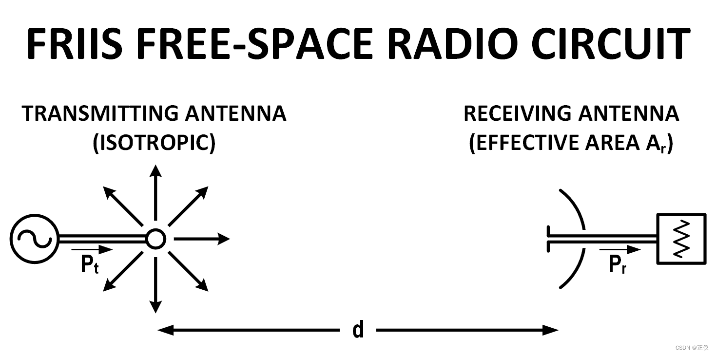
- P t P_t Pt is the power fed into the transmitting antenna input terminals;
- P r P_r Pr is the power available at receiving antenna output terminals;
- A r A_r Ar is the effective aperture area of the receiving antenna;
- A t A_t At is the effective aperture area of the transmitting antenna;
- d d d is the distance between antennas;
- λ \lambda λ is the wavelength of the radio frequency;
- P t P_t Pt and P r P_r Pr are in the same units of power;
- A r , A t , d 2 A_r, A_t, d^2 Ar,At,d2 and λ 2 \lambda^2 λ2 are in the same units.
- Distance d d d large enough to ensure a plane wave front at the receive antenna sufficiently approximated by d ≥ 2 a 2 / λ d\geq2a^2/\lambda d≥2a2/λ where a a a is the largest linear dimension of either of the antennas.
Friis stated the advantage of this formula over other formulations is the lack of numerical coefficients to remember, but does require the expression of transmitting antenna performance in terms of power flow per unit area instead of field strength and the expression of receiving antenna performance by its effective area rather than by its power gain or radiation resistance.
2. Contemporary formula
Few follow Friis’ advice on using antenna effective area to characterize antenna performance over the contemporary use of directivity and gain metrics. Replacing the effective antenna areas with their gain counterparts yields
P r P t = G t G r ( λ 4 π d ) 2 \begin{align} \frac{P_r}{P_t} =G_t G_r \left( \frac{\lambda}{4\pi d} \right)^2 \end{align} PtPr=GtGr(4πdλ)2
where G t G_t Gt and G r G_r Gr are the antenna gains (with respect to an isotropic radiator) of the transmitting and receiving antennas respectively, λ \lambda λ is the wavelength representing the effective aperture area of the receiving antenna, and d d d is the distance separating the antennas. To use the equation as written, the antenna gains are unitless values, and the units for wavelength ( λ ) (\lambda) (λ) and distance ( d ) (d) (d) must be the same.
To calculate using decibels, the equation becomes:
P
r
[
d
B
]
=
P
t
[
d
B
]
+
G
t
[
d
B
i
]
+
G
r
[
d
B
i
]
+
20
l
o
g
10
(
λ
4
π
d
)
\begin{align} P_r^{[dB]} = P_t^{[dB]} + G_t^{[dBi]} + G_r^{[dBi]} + 20 log_{10} \left( \frac{\lambda}{4\pi d} \right) \end{align}
Pr[dB]=Pt[dB]+Gt[dBi]+Gr[dBi]+20log10(4πdλ)
where
- P t [ d B ] P_t^{[dB]} Pt[dB] is the power delivered to the terminals of an isotropic transmit antenna, expressed in dB.
- P r [ d B ] P_r^{[dB]} Pr[dB] is the available power at the receive antenna terminals equal to the product of the power density of the incident wave and the effective aperture area of the receiving antenna proportional to λ 2 \lambda^{2} λ2, in d B dB dB.
- G t [ d B i ] G_t^{[dBi]} Gt[dBi] is the gain of the transmitting antenna in the direction of the receiving antenna, in dB.
- G r [ d B i ] G_r^{[dBi]} Gr[dBi] is the gain of the receiving antenna in the direction of the transmitting antenna, in dB.
The simple form applies under the following conditions:
- d ≫ λ {\displaystyle d\gg \lambda } d≫λ, so that each antenna is in the far field of the other.
- The antennas are correctly aligned and have the same polarization.
- The antennas are in unobstructed free space, with no multipath propagation.
- The bandwidth is narrow enough that a single value for the wavelength can be used to represent the whole transmission.
- Directivities are both for isotropic radiators (dBi).
- Powers are both presented in the same units: either both dBm or both dBW.
The ideal conditions are almost never achieved in ordinary terrestrial communications, due to obstructions, reflections from buildings, and most importantly reflections from the ground. One situation where the equation is reasonably accurate is in satellite communications when there is negligible atmospheric absorption; another situation is in anechoic chambers specifically designed to minimize reflections.


 2710
2710

 被折叠的 条评论
为什么被折叠?
被折叠的 条评论
为什么被折叠?
 到【灌水乐园】发言


