


 该实验涵盖了H3CNE网络工程师认证中的关键知识点,包括IP地址配置、链路聚合、VLAN命名与划分、Trunk配置、DHCP服务、OSPF区域规划、默认路由、PPP-MP认证、EASY IP访问控制及TELNET远程管理。实验特别强调了配置细节,如端口角色、验证过程及权限限制,以确保网络的正常运行和安全性。
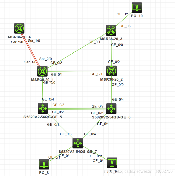
实验要求
1、按照图示配置 IP 地址
2、SW1 和 SW2 之间的直连链路配置链路聚合
3、公司内部业务网段为 Vlan10 和 Vlan20;Vlan10 是市场部,Vlan20 是技术部,要求对 Vlan 进行命名以便识别;PC1 属于 Vlan10,PC2 属于 Vlan20,Vlan30 用于 SW1 和 SW2 建立 OSPF 邻居;Vlan111 为 SW1 和 R1 的互联 Vlan,Vlan222 为 SW2 和 R2 的互联 Vlan
4、所有交换机相连的端口配置为 Trunk,允许相关流量通过
5、交换机连接 PC 的端口配置为边缘端口
6、在 SW1 上配置 DHCP 服务,为 Vlan10 和 Vlan20 的 PC 动态分配 IP 地址、网关和 DNS 地址;要求 Vlan10 的网关是 192.168.1.252,Vlan20 的网关是 192.168.2.253
7、按图示分区域配置 OSPF 实现公司内部网络全网互通,ABR 的环回口宣告进骨干区域;业务网段不允许出现协议报文
8、R1 上配置默认路由指向互联网,并引入到 OSPF
9、R1 通过双线连接到互联网,配置 PPP-MP,并配置双向 chap 验证
10、配置 EASY IP,只有业务网段 192.168.1.0/24 和 192.168.2.0/24 的数据流可以通过 R1 访问互联网
11、R1 开启 TELNET 远程管理,使用用户 abc 登录,密码 abc,只允许技术部远程管理 R1
实验拓扑
(1)各个主机的ip配置(环回口的ip是32位掩码,业务网段的ip是24位掩码,其余的交换机,路由器之间的ip是30位掩码)
[R1]dis ip int b
*down: administratively down
(s): spoofing  (l): loopback
Interface                Physical Protocol IP Address      Description
GE0/0                    up       up       10.0.0.5        --
GE0/1                    up       up       10.0.0.1        --
GE0/2                    up       up       10.0.0.14       --
Loop0                    up       up(s)    1.1.1.1         --
MP1                      up       up       202.100.1.2     --

[R2]dis ip int b
*down: administratively down
(s): spoofing  (l): loopback
Interface                Physical Protocol IP Address      Description
GE0/0                    up       up       10.0.0.9        --
GE0/1                    up       up       10.0.0.2        --
GE0/2                    up       up       10.0.0.18       --
Loop0                    up       up(s)    2.2.2.2         --

[R3]dis ip int b
*down: administratively down
(s): spoofing  (l): loopback
Interface                Physical Protocol IP Address      Description
GE0/0                    up       up       10.0.0.17       --
GE0/1                    up       up       10.0.0.13       --
GE0/2                    up       up       192.168.3.254   --
Loop0                    up       up(s)    3.3.3.3         -


[INTENET]dis ip int b
*down: administratively down
(s): spoofing  (l): loopback
Interface                Physical Protocol IP Address      Description
Loop0                    up       up(s)    100.1.1.1       --
MP1                      up       up       202.100.1.1     --

[SW1]dis ip int b
*down: administratively down
(s): spoofing  (l): loopback
Interface                Physical Protocol IP Address      Description
Loop0                    up       up(s)    11.11.11.11     --
Vlan10                   up       up       192.168.1.252   --
Vlan20                   up       up       192.168.2.252   --
Vlan30                   up       up       10.1.2.1        --
Vlan100                  up       up       10.0.0.6        --

[SW2]dis ip int b
*down: administratively down
(s): spoofing  (l): loopback
Interface                Physical Protocol IP Address      Description
Loop0
最低0.47元/天 解锁文章


 6609
6609

 被折叠的 条评论
为什么被折叠?
被折叠的 条评论
为什么被折叠?
 到【灌水乐园】发言


