


0x00 防火墙双机热备简介
防火墙双机热备(Firewall High Availability, 简称HA)是一种提高网络安全设备(如防火墙)可靠性和可用性的技术方案。通过部署两台防火墙设备(主备两台),实现设备之间的冗余和故障切换,当其中一台防火墙出现故障时,另一台能够自动接管,确保网络服务不中断。
1. 双机模式
- 主-备模式(Active/Standby):在这种模式下,一台防火墙处于“主”状态,负责处理所有的网络流量,另一台处于“备”状态,时刻准备接管。当主防火墙出现故障时,备防火墙立即切换到主设备,接管流量。
- 主-主模式(Active/Active):两台防火墙设备同时处理不同的网络流量,互为备份。如果其中一台发生故障,另一台可以接管其流量。这种模式可以提高设备利用率,但相对复杂。
2. 状态同步
在双机热备方案中,防火墙之间会进行会话状态(Session State)和配置的同步,以确保在故障切换时,流量的状态不丢失。比如,主防火墙上的连接信息、NAT状态等会实时同步到备防火墙。
3. 故障检测
双机防火墙通过心跳检测(Heartbeat)机制来监控对方的健康状态。一般使用专用的心跳接口进行通信。如果主防火墙的心跳信号丢失,备防火墙就会判断主防火墙故障,并自动接管业务。
4. 故障切换
当主防火墙检测到自身的硬件或软件故障时,备防火墙会在极短时间内切换到主状态。切换过程中,备防火墙根据之前同步的状态信息继续处理现有的网络连接,尽量减少对业务的影响。
5. 优势
- 高可用性:双机热备提供了冗余,确保即使其中一台设备故障,业务也能无缝切换,不影响网络的正常运行。
- 容错能力:通过实时状态同步,双机热备可以有效避免单点故障,增加网络的容错能力。
- 快速恢复:设备故障时的切换速度很快,用户可能感知不到网络的中断。
6. 配置与应用场景
防火墙双机热备主要应用于对网络安全要求较高的环境中,如企业级网络、数据中心等,确保安全设备不成为网络中的单点故障。具体配置方式因厂商不同而异,但一般会包括以下步骤:
- 设置双机设备的IP地址及心跳接口。
- 配置主备关系及切换优先级。
- 开启并配置状态同步。
- 定期监控双机热备的状态。
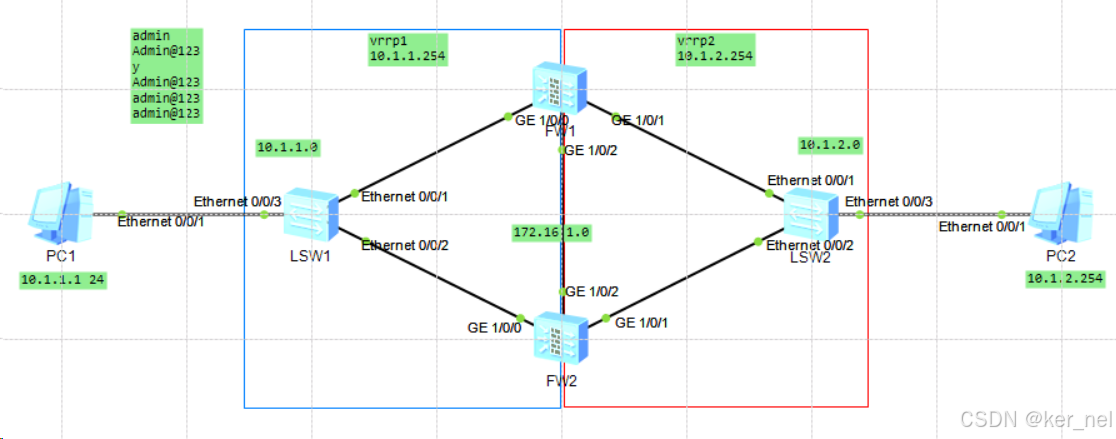
0x01 实验1——上二下二双机热备
输入密码
admin
Admin@123
y
Admin@123
admin@123
admin@123
关闭日志
undo info-center enable
1.配置FW1接口IP地址
[FW1]int g1/0/0
[FW1-GigabitEthernet1/0/0]ip add 10.1.1.11 24
[FW1-GigabitEthernet1/0/0]int g1/0/1
[FW1-GigabitEthernet1/0/1]ip add 10.1.2.11 24
[FW1-GigabitEthernet1/0/1]int g 1/0/2
[FW1-GigabitEthernet1/0/2]ip add 172.16.1.11 24
[FW1-GigabitEthernet1/0/2]q
[FW1]
2.划分FW1安全区域
[FW1]firewall zone trust
[FW1-zone-trust]add interface g1/0/0
[FW1-zone-trust]q
[FW1]firewall zone untrust
[FW1-zone-untrust]add interface g1/0/1
[FW1-zone-untrust]q
[FW1]firewall zone dmz
[FW1-zone-dmz]add interface g1/0/2
[FW1-zone-dmz]q
[FW1]
3.配置完成后使用dis zone查看
[FW1]dis zone
2023-12-20 03:08:33.990
local
priority is 100
interface of the zone is (0):
#
trust
priority is 85
interface of the zone is (2):
GigabitEthernet0/0/0
GigabitEthernet1/0/0
#
untrust
priority is 5
interface of the zone is (1):
GigabitEthernet1/0/1
#
dmz
priority is 50
interface of the zone is (1):
GigabitEthernet1/0/2
#
[FW1]
4.配置FW2接口IP地址
[FW2]int g1/0/0
[FW2-GigabitEthernet1/0/0]ip add 10.1.1.22 24
[FW2-GigabitEthernet1/0/0]q
[FW2]int g1/0/1
[FW2-GigabitEthernet1/0/1]ip add 10.1.2.22 24
[FW2-GigabitEthernet1/0/1]q
[FW2]int g1/0/2
[FW2-GigabitEthernet1/0/2]ip add 172.16.1.22 24
[FW2-GigabitEthernet1/0/2]q
[FW2]
5.划分FW2安全区域
[FW2]firewall zone trust
[FW2-zone-trust]add interface g1/0/0
[FW2-zone-trust]q
[FW2]firewall zone untrust
[FW2-zone-untrust]add interface g1/0/1
[FW2-zone-untrust]q
[FW2]firewall zone dmz
[FW2-zone-dmz]add interface g1/0/2
[FW2-zone-dmz]q
[FW1]
6.配置完成后使用dis zone查看
[FW2]dis zone
2023-12-20 03:15:54.280
local
priority is 100
interface of the zone is (0):
#
trust
priority is 85
interface of the zone is (2):
GigabitEthernet0/0/0
GigabitEthernet1/0/0
#
untrust
priority is 5
interface of the zone is (1):
GigabitEthernet1/0/1
#
dmz
priority is 50
interface of the zone is (1):
GigabitEthernet1/0/2
#
[FW2]
7.配置FW1的vrrp,FW1为主设备
[FW1]int g1/0/0
[FW1-GigabitEthernet1/0/0]vrrp vrid 1 virtual-ip 10.1.1.254 active
[FW1-GigabitEthernet1/0/0]q
[FW1]int g1/0/1
[FW1-GigabitEthernet1/0/1]vrrp vrid 2 virtual-ip 10.1.2.254 active
[FW1-GigabitEthernet1/0/1]q
[FW1]
8.配置FW2的vrrp,FW2为备设备
[FW2]int g1/0/0
[FW2-GigabitEthernet1/0/0]vrrp vrid 1 virtual-ip 10.1.1.254 standby
[FW2-GigabitEthernet1/0/0]q
[FW2]int g1/0/1
[FW2-GigabitEthernet1/0/1]vrrp vrid 2 virtual-ip 10.1.2.254 standby
[FW2-GigabitEthernet1/0/1]q
[FW2]
9.配置心跳接口,开启双机热备
FW1
[FW1]hrp interface g1/0/2 remote 172.16.1.22
[FW1]hrp enable
Info: NAT IP detect function is disabled.
HRP_S[FW1]
FW2
[FW2]hrp interface g1/0/2 remote 172.16.1.11
[FW2]hrp enable
Info: NAT IP detect function is disabled.
HRP_S[FW2]
10.配置安全策略
PC1和PC2互通,只需要在主设备上配置,会同步到备设备上
FW1
HRP_M[FW1]security-policy (+B)
HRP_M[FW1-policy-security]rule name pc1-pc2 (+B)
HRP_M[FW1-policy-security-rule-pc1-pc2]source-zone trust (+B)
HRP_M[FW1-policy-security-rule-pc1-pc2]destination-zone untrust (+B)
HRP_M[FW1-policy-security-rule-pc1-pc2]source-address 10.1.1.0 24 (+B)
HRP_M[FW1-policy-security-rule-pc1-pc2]destination-address 10.1.2.0 24 (+B)
HRP_M[FW1-policy-security-rule-pc1-pc2]action permit (+B)
HRP_M[FW1-policy-security-rule-pc1-pc2]dis th
2023-12-20 04:23:42.870
#
rule name pc1-pc2
source-zone trust
destination-zone untrust
source-address 10.1.1.0 mask 255.255.255.0
destination-address 10.1.2.0 mask 255.255.255.0
action permit
#
return
HRP_M[FW1-policy-security-rule-pc1-pc2]`
(+B)代表备份
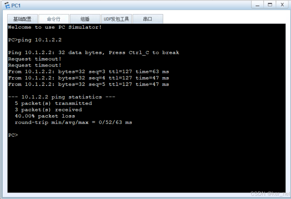
此时用pc1去ping pc2,能够正常ping通
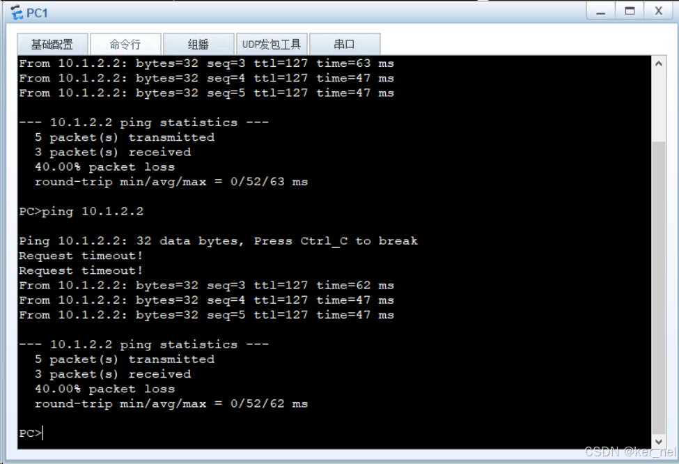
11.检验双机热备是否正常,手动关闭主设备端口
HRP_M[FW1]int g1/0/0 (+B)
HRP_M[FW1-GigabitEthernet1/0/0]sh
HRP_M[FW1-GigabitEthernet1/0/0]shutdown
再次ping pc2依然能够正常通信,说明双机热备能够正常切换主备
13.新建安全区域
[FW2]firewall zone name isp1
[FW2-zone-isp1]set priority 45
[FW2-zone-isp1]dis th
2023-12-20 03:17:54.880
#
firewall zone name isp1 id 4
set priority 45
#
return
[FW2-zone-isp1]
设置优先级,100、85、50、5这几个已经存在的不可使用
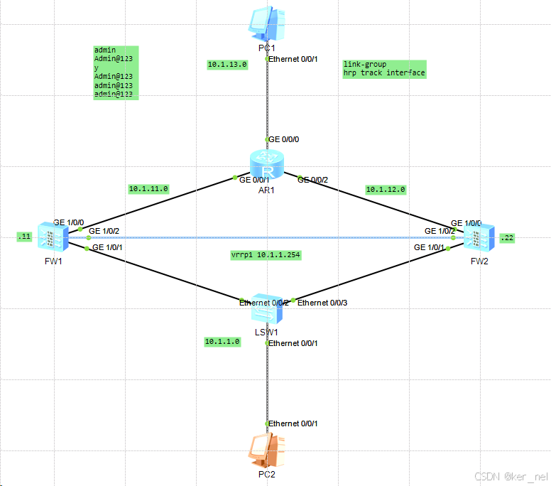
0x02 实验2——上三下二双机热备
topo
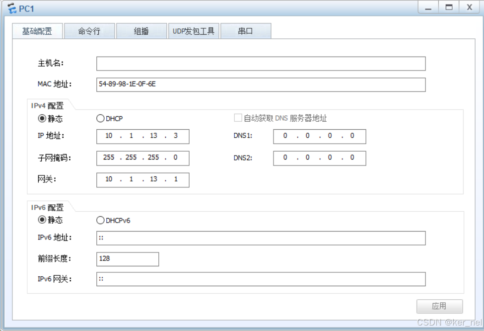
PC1
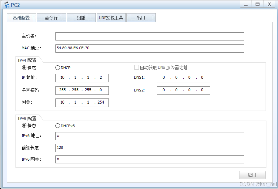
PC2
1.配置设备接口IP地址
AR1
[AR1]int g0/0/0
[AR1-GigabitEthernet0/0/0]ip add 10.1.13.1 24
[AR1-GigabitEthernet0/0/0]q
[AR1]int g0/0/1
[AR1-GigabitEthernet0/0/1]ip add 10.1.11.1 24
[AR1-GigabitEthernet0/0/1]q
[AR1]int g0/0/2
[AR1-GigabitEthernet0/0/2]ip add 10.1.12.1 24
[AR1-GigabitEthernet0/0/2]q
[AR1]
FW1
[FW1]int g1/0/0
[FW1-GigabitEthernet1/0/0]ip add 10.1.11.11 24
[FW1-GigabitEthernet1/0/0]q
[FW1]int g1/0/1
[FW1-GigabitEthernet1/0/1]ip add 10.1.1.11 24
[FW1-GigabitEthernet1/0/1]q
[FW1]int g1/0/2
[FW1-GigabitEthernet1/0/2]ip add 10.1.2.11 24
[FW1-GigabitEthernet1/0/2]q
[FW1]
FW2
[FW2]int g1/0/0
[FW2-GigabitEthernet1/0/0]ip add 10.1.12.22 24
[FW2-GigabitEthernet1/0/0]q
[FW2]int g1/0/1
[FW2-GigabitEthernet1/0/1]ip add 10.1.1.22 24
[FW2-GigabitEthernet1/0/1]q
[FW2]int g1/0/2
[FW2-GigabitEthernet1/0/2]ip add 10.1.2.22 24
[FW2-GigabitEthernet1/0/2]q
[FW2]
2.配置防火墙安全区域
FW1
[FW1]firewall zone trust
[FW1-zone-trust]add interface g1/0/1
[FW1-zone-trust]q
[FW1]firewall zone untrust
[FW1-zone-untrust]add interface g1/0/0
[FW1-zone-untrust]q
[FW1]firewall zone dmz
[FW1-zone-dmz]add interface g1/0/2
[FW1-zone-dmz]q
[FW1]
FW2
[FW2]firewall zone trust
[FW2-zone-trust]add interface g1/0/1
[FW2-zone-trust]q
[FW2]firewall zone untrust
[FW2-zone-untrust]add interface g1/0/0
[FW2-zone-untrust]q
[FW2]firewall zone dmz
[FW2-zone-dmz]add interface g1/0/2
[FW2-zone-dmz]q
[FW2]
3.配置vrrp1,FW1为主FW2为备
FW1
[FW1]int g1/0/1
[FW1-GigabitEthernet1/0/1]vrrp vrid 1 virtual-ip 10.1.1.254 active
[FW1-GigabitEthernet1/0/1]dis th
2023-12-20 11:37:15.810
#
interface GigabitEthernet1/0/1
undo shutdown
ip address 10.1.1.11 255.255.255.0
vrrp vrid 1 virtual-ip 10.1.1.254 active
#
return
[FW1-GigabitEthernet1/0/1]
FW2
[FW2]int g1/0/1
[FW2-GigabitEthernet1/0/1]vrrp vrid 1 virtual-ip 10.1.1.254 standby
[FW2-GigabitEthernet1/0/1]dis th
2023-12-20 11:38:06.770
#
interface GigabitEthernet1/0/1
undo shutdown
ip address 10.1.1.22 255.255.255.0
vrrp vrid 1 virtual-ip 10.1.1.254 standby
#
return
[FW2-GigabitEthernet1/0/1]
4.配置心跳接口,开启双机热备
FW1
[FW1]hrp interface g1/0/2 remote 10.1.2.22
[FW1]hrp enable
Info: NAT IP detect function is disabled.
HRP_S[FW1]
FW2
[FW2]hrp interface g1/0/2 remote 10.1.2.11
[FW2]hrp enable
Info: NAT IP detect function is disabled.
HRP_S[FW2]
5.配置link-group(二选一)
FW1
HRP_M[FW1]int g1/0/0 (+B)
HRP_M[FW1-GigabitEthernet1/0/0]link-group 1
HRP_M[FW1-GigabitEthernet1/0/0]q
HRP_M[FW1]int g1/0/1 (+B)
HRP_M[FW1-GigabitEthernet1/0/1]link-group 1
HRP_M[FW1-GigabitEthernet1/0/1]q
6.配置hrp监测上行接口(二选一)
FW2
HRP_S[FW2]hrp track interface g1/0/0
7.配置路由
FW1
HRP_M[FW1]ip route-static 10.1.13.0 24 10.1.11.1
FW2
HRP_S[FW2]ip route-static 10.1.13.0 24 10.1.12.1
AR1
[AR1]ip route-static 10.1.1.0 24 10.1.11.11
[AR1]ip route-static 10.1.1.0 24 10.1.12.22 preference 100
8.配置安全策略,协议为允许icmp通过
FW1
HRP_M[FW1]security-policy (+B)
HRP_M[FW1-policy-security]rule name pc2-pc1 (+B)
HRP_M[FW1-policy-security-rule-pc2-pc1]source-zone trust (+B)
HRP_M[FW1-policy-security-rule-pc2-pc1]destination-zone untrust (+B)
HRP_M[FW1-policy-security-rule-pc2-pc1]source-address 10.1.1.0 24 (+B)
HRP_M[FW1-policy-security-rule-pc2-pc1]destination-address 10.1.13.0 24 (+B)
HRP_M[FW1-policy-security-rule-pc2-pc1]service icmp (+B)
HRP_M[FW1-policy-security-rule-pc2-pc1]action permit (+B)
HRP_M[FW1-policy-security-rule-pc2-pc1]dis th
2023-12-20 11:54:09.210
#
rule name pc2-pc1
source-zone trust
destination-zone untrust
source-address 10.1.1.0 mask 255.255.255.0
destination-address 10.1.13.0 mask 255.255.255.0
service icmp
action permit
#
return
HRP_M[FW1-policy-security-rule-pc2-pc1]
9.查看hrp状态
FW1
HRP_M[FW1]dis hrp state
2023-12-20 11:54:46.030
Role: active, peer: standby
Running priority: 45000, peer: 45000
Backup channel usage: 0.00%
Stable time: 0 days, 0 hours, 14 minutes
Last state change information: 2023-12-20 11:40:33 HRP core state changed, old_
state = abnormal(standby), new_state = normal, local_priority = 45000, peer_prio
rity = 45000.HRP_M[FW1]
10.测试
pc2 ping pc1
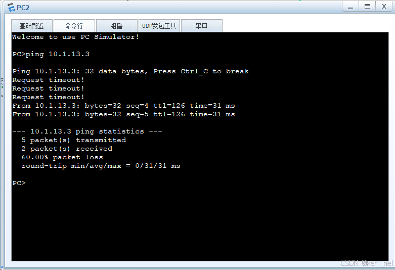
关闭FW1上的g1/0/0
HRP_M[FW1]int g1/0/0 (+B)
HRP_M[FW1-GigabitEthernet1/0/0]shutdown
此时在FW2上查看hrp状态,可以看到主备已经切换成功
HRP_M[FW2]dis hrp state
2023-12-20 11:58:06.120
Role: active, peer: standby (should be "standby-active")
Running priority: 45000, peer: 44998
Backup channel usage: 0.00%
Stable time: 0 days, 0 hours, 0 minutes
Last state change information: 2023-12-20 11:57:17 HRP core state changed, old_
state = normal, new_state = abnormal(active), local_priority = 45000, peer_prior
ity = 44998.HRP_M[FW2]


 5695
5695

 被折叠的 条评论
为什么被折叠?
被折叠的 条评论
为什么被折叠?
 到【灌水乐园】发言


