


实验拓扑:

先配置ospf使得公网能通:
R2:
interface GigabitEthernet0/0/1
ip address 23.1.1.1 255.255.255.0
interface LoopBack0
ip address 2.2.2.2 255.255.255.0
ospf 1 router-id 2.2.2.2
area 0.0.0.0
network 2.2.2.2 0.0.0.0
network 23.1.1.1 0.0.0.0
R3:
interface GigabitEthernet0/0/0
ip address 23.1.1.2 255.255.255.0
interface GigabitEthernet0/0/1
ip address 34.1.1.1 255.255.255.0
interface LoopBack0
ip address 3.3.3.3 255.255.255.0
ospf 1 router-id 3.3.3.3
area 0.0.0.0
network 3.3.3.3 0.0.0.0
network 23.1.1.2 0.0.0.0
network 34.1.1.1 0.0.0.0
R4:
interface GigabitEthernet0/0/0
ip address 34.1.1.2 255.255.255.0
interface LoopBack0
ip address 4.4.4.4 255.255.255.0
interface GigabitEthernet4/0/0
ip address 47.1.1.2 255.255.255.0
ospf 1 router-id 4.4.4.4
area 0.0.0.0
network 4.4.4.4 0.0.0.0
network 34.1.1.2 0.0.0.0
network 47.1.1.2 0.0.0.0
公网通了以后,做MPLS:
(要进入接口做)
R2:
mpls lsr-id 2.2.2.2
mpls ldp
int g0/0/0
mpls
mpls ldp
R3 和 R4 相同
MPLS做完,起BGP:
R2:
bgp 1
router-id 2.2.2.2
peer 4.4.4.4 as-number 1
peer 4.4.4.4 connect-interface LoopBack0
peer 4.4.4.4 next-hop-local
R4:
bgp 1
router-id 4.4.4.4
peer 2.2.2.2 as-number 1
peer 2.2.2.2 connect-interface LoopBack0
peer 2.2.2.2 next-hop-local
给R1/5/6/7配置环回和地址:
R 1:
interface LoopBack0
ip address 192.168.1.1 255.255.255.0
interface GigabitEthernet0/0/1
ip address 192.168.2.1 255.255.255.0
R5:
interface LoopBack0
ip address 192.168.4.1 255.255.255.0
interface GigabitEthernet0/0/0
ip address 192.168.3.1 255.255.255.0
R6:
interface LoopBack0
ip address 192.168.1.1 255.255.255.0
interface GigabitEthernet0/0/2
ip address 192.168.2.1 255.255.255.0
R7:
interface LoopBack0
ip address 192.168.4.2 255.255.255.0
interface GigabitEthernet0/0/2
ip address 192.168.3.1 255.255.255.0
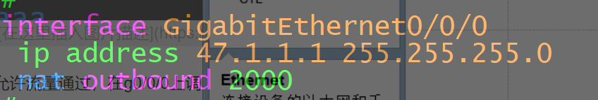
interface GigabitEthernet0/0/0
ip address 47.1.1.1 255.255.255.0
在R2和R4上写MPLS-VPN:
R2:
[r2]ip vpn-instance a 创建名为a的vrf空间
[r2-vpn-instance-a]ipv4-family 进入IPV4的配置模式下
[r2-vpn-instance-a-af-ipv4]route-distinguisher 1:1 RD值
[r2-vpn-instance-a-af-ipv4]vpn-target 1:1 RT值 必须对端的PE端一致
[r2]interface GigabitEthernet 0/0/0 进入链接CE端的接口
[r2-GigabitEthernet0/0/0]ip binding vpn-instance a 关联到vrf空间
[r2-GigabitEthernet0/0/0]ip address 192.168.2.2 24
R4:
[r4]ip vpn-instance a 创建名为a的vrf空间
[r4-vpn-instance-a]ipv4-family 进入IPV4的配置模式下
[r4-vpn-instance-a-af-ipv4]route-distinguisher 1:1 RD值
[r4-vpn-instance-a-af-ipv4]vpn-target 1:1 RT值 必须对端的PE端一致
[r4]interface GigabitEthernet 0/0/1 进入链接CE端的接口
[r4-GigabitEthernet0/0/1]ip binding vpn-instance a 关联到vrf空间
[r4-GigabitEthernet0/0/1]ip address 192.168.3.2 24
在R2 和 R4 上的 ip vpn-instance b 配置差不多一样
PE与PE间建立MP-BPG邻居关系
[r2]bgp 1
需要再在IPV4的家族模式中,与对端建立一个VPNV4的关系,用于传递VPNV4路由
[r2-bgp]ipv4-family vpnv4
[r2-bgp-af-vpnv4]peer 4.4.4.4 enable
[r2-bgp]display bgp vpnv4 all peer 查看mp-bgp邻居关系
[r4]bgp 21
同时还需要再在IPV4的家族模式中,与对端建立一个VPNV4的关系,用于传递VPNV4路由
[r4-bgp]ipv4-family vpnv4
[r4-bgp-af-vpnv4]peer 2.2.2.2 enable
[r4-bgp]display bgp vpnv4 all peer 查看mp-bgp邻居关系
CE端与PE端交互路由:静态
R1:
ip route-static 192.168.3.0 255.255.255.0 192.168.2.2
ip route-static 192.168.4.0 255.255.255.0 192.168.2.2
R2:
ip route-static vpn-instance a 192.168.1.0 255.255.255.0 192.168.2.1
[r2]bgp 1
[r2-bgp]ipv4 vpn-instance a
[r2-bgp-a]import-route direct
[r2-bgp-a]import-route static
R5:
ip route-static 192.168.1.0 255.255.255.0 192.168.3.2
ip route-static 192.168.2.0 255.255.255.0 192.168.3.2
R4:
ip route-static vpn-instance a 192.168.4.0 255.255.255.0 192.168.3.1
[r4]bgp 1
[r4-bgp]ipv4 vpn-instance a
[r4-bgp-a]import-route direct
[r4-bgp-a]import-route static
A1用RIP,A2用OSPF:
R6:
rip 1
undo summary
version 2
network 192.168.1.0
network 192.168.2.0
R2:
rip 1 vpn-instance b
undo summary
version 2
network 192.168.2.0
import-route bgp
bgp 1
ipv4-family vpn-instance b
import-route rip 1
R7:
ospf 2 router-id 7.7.7.7
area 0.0.0.0
network 192.168.3.1 0.0.0.0
network 192.168.4.2 0.0.0.0
R4:
ospf 2 vpn-instance b
import-route bgp
area 0.0.0.0
network 192.168.3.2 0.0.0.0
bgp 1
ipv4-family vpn-instance a
import-route ospf 2
ospf 2 vpn-instance a
import-route bgp
查看路由表:


测试:

R1可以ping 通4.1

R6可以ping 通4.2
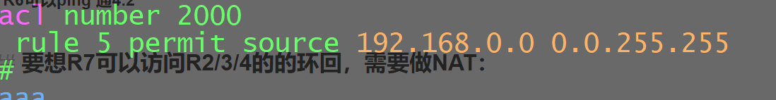
要想R7可以访问R2/3/4的的环回,需要做NAT:
首先在R7上写acl
允许流量通过,在g0/0/0上调用acl
测试:

实验完成!!!


 687
687


 被折叠的 条评论
为什么被折叠?
被折叠的 条评论
为什么被折叠?
 到【灌水乐园】发言


