


 本文详细描述了一个华为路由器实验,涉及MGRE网络环境搭建、PPP和CHAP认证配置、HDLC封装、NAT转换以及RIP路由协议的配置过程,展示了如何在实验环境下实现网络通信和路由可达性。
一、实验拓扑图及要求
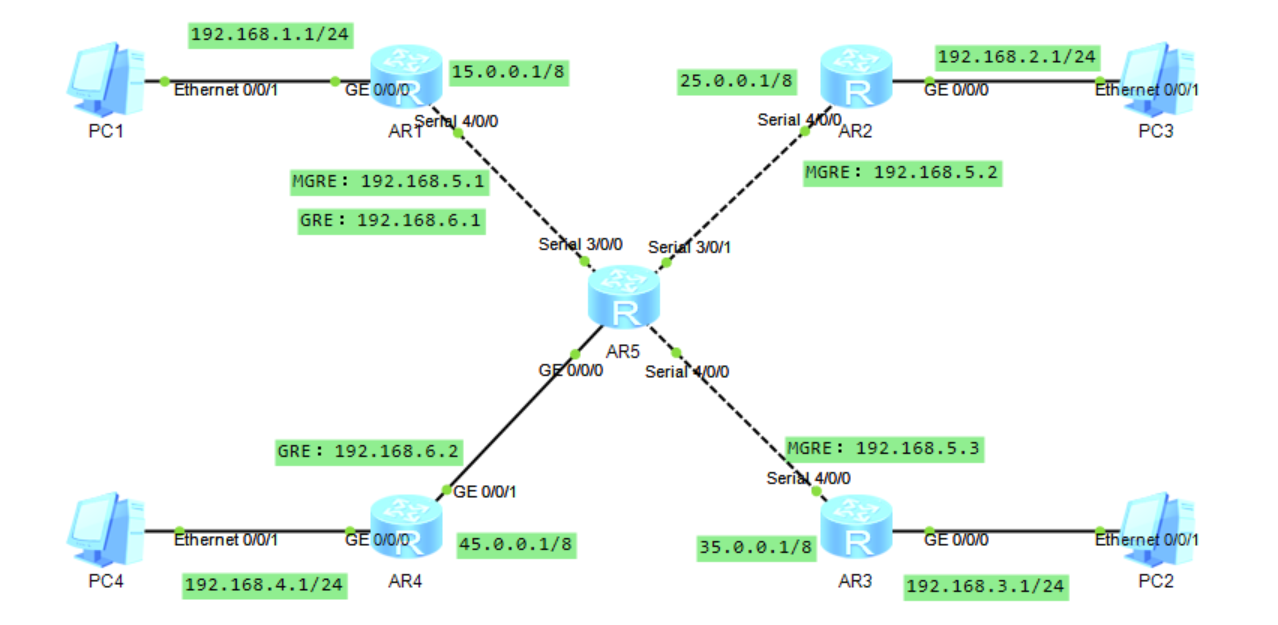
1.拓扑图
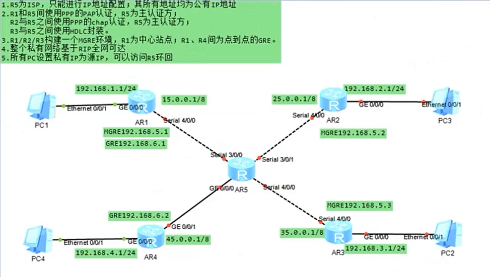
2.要求
- R5为ISP,只能进行IP地址配置,其所有地址均为公有IP地址
- R1和R5间使用PPP的PAP认证,R5为主认证方
R2与R5之间使用PPP的chap认证,R5为主认证方
R3与R5之间使用HDLC封装 - R1/R2/R3构建一个MGRE环境,R1为中心站点,R1、R4间为点到点的FRE
- 整个私有网络基于RIP全网可达
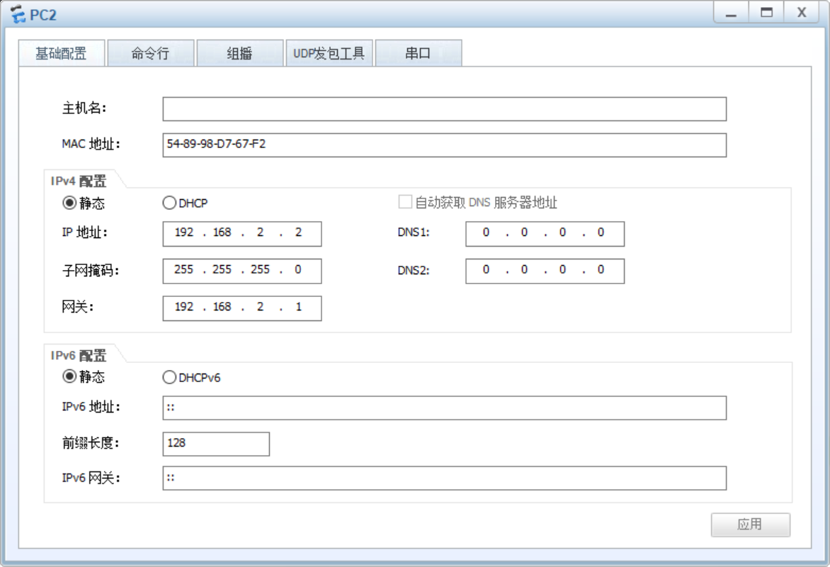
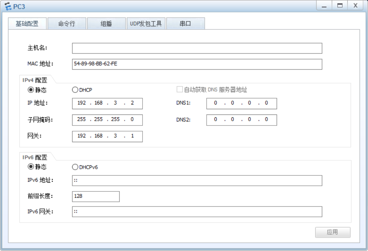
- 所有PC设置私有IP为源IP,可以访问R5环回
二、根据题意搭建拓扑
三、实验配置


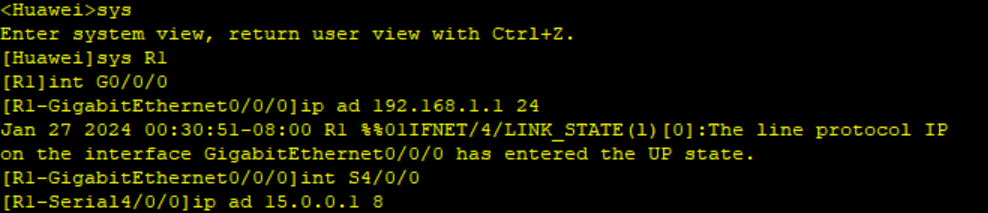
R1:
<Huawei>sys
[Huawei]sys R1
[R1]int G0/0/0
[R1-GigabitEthernet0/0/0]ip ad 192.168.1.1 24
[R1-GigabitEthernet0/0/0]int S4/0/0
[R1-Serial4/0/0]ip ad 15.0.0.1 8
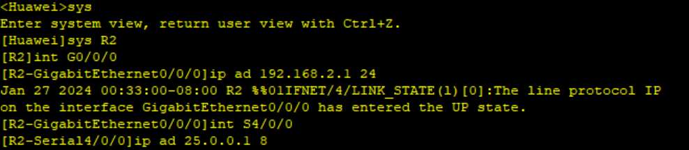
R2:
<Huawei>sys
[Huawei]sys R2
[R2]int G0/0/0
[R2-GigabitEthernet0/0/0]ip ad 192.168.2.1 24
[R2-GigabitEthernet0/0/0]int S4/0/0
[R2-Serial4/0/0]ip ad 25.0.0.1 8
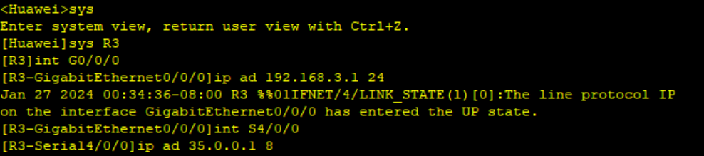
R3:
<Huawei>sys
[Huawei]sys R3
[R3]int G0/0/0
[R3-GigabitEthernet0/0/0]ip ad 192.168.3.1 24
[R3-GigabitEthernet0/0/0]int S4/0/0
[R3-Serial4/0/0]ip ad 35.0.0.1 8
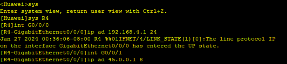
R4:
<Huawei>sys
[Huawei]sys R4
[R4]int G0/0/0
[R4-GigabitEthernet0/0/0]ip ad 192.168.4.1 24
[R4-GigabitEthernet0/0/0]int G0/0/1
[R4-GigabitEthernet0/0/1]ip ad 45.0.0.1 8
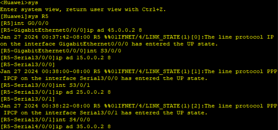
R5:
<Huawei>sys
[Huawei]sys R5
[R5]int G0/0/0
[R5-GigabitEthernet0/0/0]ip ad 45.0.0.2 8
[R5-GigabitEthernet0/0/0]int S3/0/0
[R5-Serial3/0/0]ip ad 15.0.0.2 8
[R5-Serial3/0/0]int S3/0/1
[R5-Serial3/0/1]ip ad 25.0.0.2 8
[R5-Serial3/0/1]int S4/0/0
[R5-Serial4/0/0]ip ad 35.0.0.2 8
配置缺省路由
R1:
[R1]ip route-static 0.0.0.0 0 15.0.0.2

R2:
[R2]ip route-static 0.0.0.0 0 25.0.0.2

R3:
[R3]ip route-static 0.0.0.0 0 35.0.0.2

R4:
[R4]ip route-static 0.0.0.0 0 45.0.0.2

配置acl访问控制列表
配置NAT出站
用于将内部网络中的私有IP地址转换为公共IP地址,以实现与外部网络的通信。
R1:
[R1]acl 2000
[R1-acl-basic-2000]rule permit source 192.168.1.0 0.0.0.255
[R1-acl-basic-2000]q
[R1]int S4/0/0
[R1-Serial4/0/0]nat outbound 2000

R2:
[R2]acl 2000
[R2-acl-basic-2000]rule permit source 192.168.2.0 0.0.0.255
[R2-acl-basic-2000]q
[R2]int S4/0/0
[R2-Serial4/0/0]nat outbound 2000

R3:
[R3]acl 2000
[R3-acl-basic-2000]rule permit source 192.168.3.0 0.0.0.255
[R3-acl-basic-2000]q
[R3]int S4/0/0
[R3-Serial4/0/0]nat outbound 2000

R4:
[R4]acl 2000
[R4-acl-basic-2000]rule permit source 192.168.4.1 0.0.0.255
[R4-acl-basic-2000]q
[R4]int G0/0/0
[R4-GigabitEthernet0/0/0]nat outbound 2000

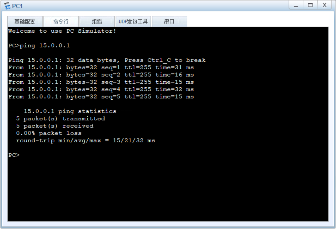
ping命令测试
R1:
创建虚拟隧道配置IP地址
[R1]int Tunnel 0/0/0
[R1-Tunnel0/0/0]ip ad 192.168.5.1 24

在接口上封装MGRE协议
[R1-Tunnel0/0/0]tunnel-protocol gre p2mp

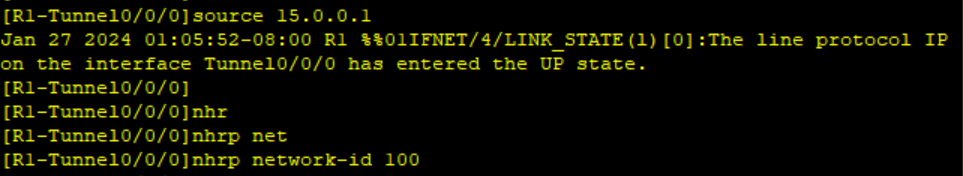
在接口上封装源接口,使用nhrp协议帮其他私网划分在一个区域内
[R1-Tunnel0/0/0]source 15.0.0.1
[R1-Tunnel0/0/0]nhrp network-id 100
R2:
创建虚拟隧道配置IP地址
[R2]int Tunnel 0/0/0
[R2-Tunnel0/0/0]ip ad 192.168.5.2 24

在接口上封装MGRE协议
[R2-Tunnel0/0/0]tunnel-protocol gre p2mp

在接口上封装源接口
[R2-Tunnel0/0/0]source S4/0/0

在NHRP中注册一个条目
使用"NHRP entry +主虚拟接口IP+主边界接口的IP register"在NHRP中注册一个条目,其中包括主虚拟接口IP和主边界接口的IP。
[R2-Tunnel0/0/0]nhrp network-id 100
[R2-Tunnel0/0/0]nhrp entry 192.168.5.1 15.0.0.1 register

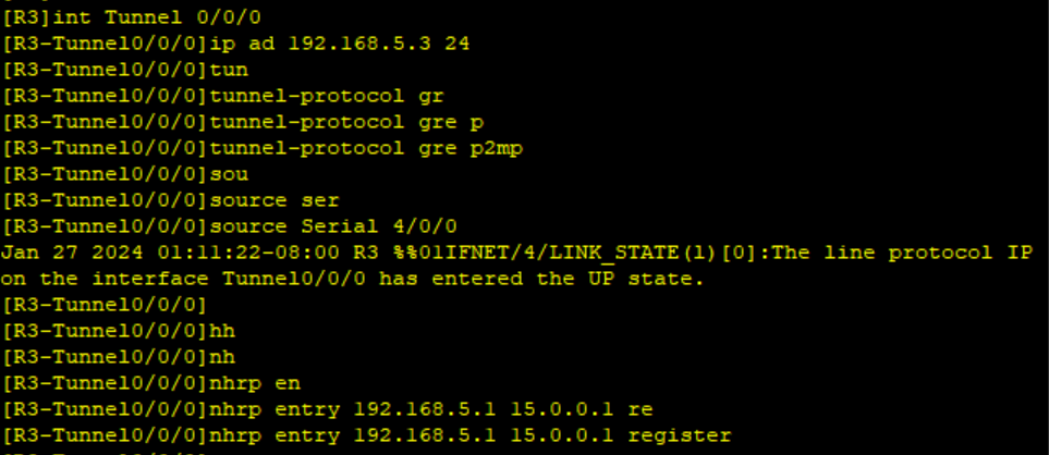
R3:
[R3]int Tunnel 0/0/0
[R3-Tunnel0/0/0]ip ad 192.168.5.3 24
[R3-Tunnel0/0/0]tunnel-protocol gre p2mp
[R3-Tunnel0/0/0]source Serial 4/0/0
[R3-Tunnel0/0/0]nhrp entry 192.168.5.1 15.0.0.1 register
GRE封装
创建一个点到点的虚拟链路,将数据包封装在IP包中传输,从而在不同的网络中传输数据。
R1:
[R1]int Tunnel 0/0/1
[R1-Tunnel0/0/1]ip ad 192.168.6.1 24
[R1-Tunnel0/0/1]tunnel-protocol gre
[R1-Tunnel0/0/1]source 15.0.0.1
[R1-Tunnel0/0/1]description 45.0.0.1

R4:
[R4]int Tunnel 0/0/0
[R4-Tunnel0/0/0]ip ad 192.168.6.2 24
[R4-Tunnel0/0/0]tunnel-protocol gre
[R4-Tunnel0/0/0]source 45.0.0.1
[R4-Tunnel0/0/0]description 15.0.0.1

配置RIP
R1:
[R1]rip 1
[R1-rip-1]verify-source
[R1-rip-1]version 2
[R1-rip-1]network 192.168.1.0
[R1-rip-1]network 192.168.5.0
[R1-rip-1]network 192.168.6.0

R2:
[R2]rip 1
[R2-rip-1]verify-source
[R2-rip-1]version 2
[R2-rip-1]network 192.168.2.0
[R2-rip-1]network 192.168.5.0

R3:
[R3]rip 1
[R3-rip-1]verify-source
[R3-rip-1]version 2
[R3-rip-1]network 192.168.3.0
[R3-rip-1]network 192.168.5.0

R4:
[R4]rip 1
[R4-rip-1]verify-source
[R4-rip-1]version 2
[R4-rip-1]network 192.168.4.0
[R4-rip-1]network 192.168.6.0

开启伪广播
R1:
[R1]int Tunnel 0/0/0
[R1-Tunnel0/0/0]nhrp entry multicast dynamic

R2:
[R2]int Tunnel 0/0/0
[R2-Tunnel0/0/0]nhrp entry multicast dynamic

R3:
[R3]int Tunnel 0/0/0
[R3-Tunnel0/0/0]nhrp entry multicast dynamic

关闭RIP的水平分割
R1:
[R1-Tunnel0/0/0]undo rip split-horizon

R2:
[R2-Tunnel0/0/0]undo rip split-horizon

R3:
[R3-Tunnel0/0/0]undo rip split-horizon

测试全网可达


 443
443


 被折叠的 条评论
为什么被折叠?
被折叠的 条评论
为什么被折叠?
 到【灌水乐园】发言


