


 本文介绍了在STM32中配置LCD的方法。首先在STM32CubeMX里将LCD的IO配置为GPIO - OUTPUT模式,生成Keil代码后复制lcd.c和lcd.h文件到工程中。进入Keil工程,在主函数对LCD初始化、清屏并设置颜色,编译无误后烧录到板子。
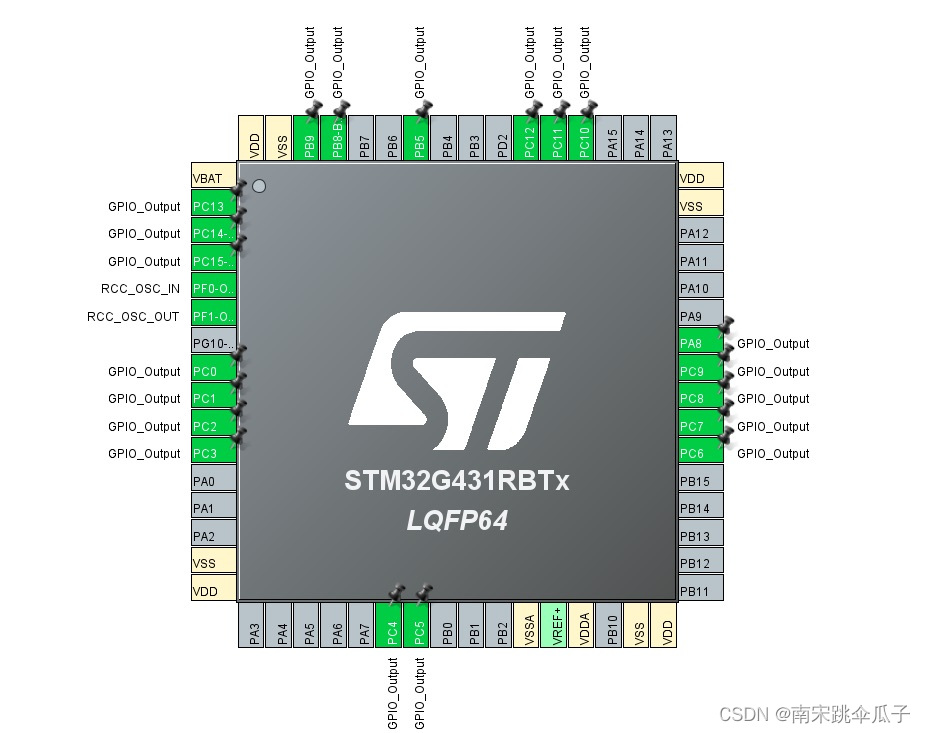
1.STM32CubeMX中,只需对LCD的所有IO配置为GPIO-OUTPUT模式即可。
LCD所需引脚可以查看原理图。
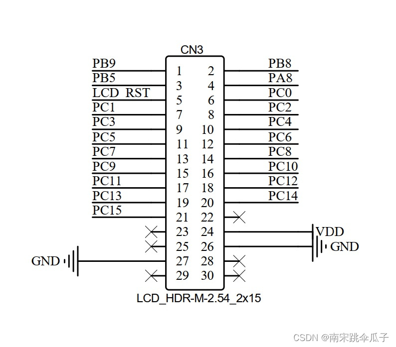
STM32CubeMX引脚配置完成后如图所示。
2. 生成keil代码后,复制lcd.c和lcd.h文件至当前keil工程文件中。可以自己新建文件复制这里的lcd.c和lcd.h内容,也可以在总览的那篇博客中的网盘链接中下载LCD例程,复制里面的lcd.c和lcd.h文件。
lcd.c如下:
/*
  程序说明: CT117E嵌入式竞赛板LCD驱动程序
  软件环境: Keil uVision 4.10
  硬件环境: CT117E嵌入式竞赛板
  日    期: 2011-8-9
*/
#include "lcd.h"
#include "fonts.h"
//#include "systick.h"
static  vu16 TextColor = 0x0000, BackColor = 0xFFFF;
vu16 dummy;

/*******************************************************************************
* Function Name  : Delay_LCD
* Description    : Inserts a delay time.
* Input          : nCount: specifies the delay time length.
* Output         : None
* Return         : None
*******************************************************************************/
void Delay_LCD(u16 n)
{
    u16 i, j;
    for (i = 0; i < n; ++i)
        for(j = 0; j < 3000; ++j);
}

/*
	uC8230型液晶控制器寄存器配置
*/
void REG_8230_Init(void)
{
    LCD_WriteReg(0x0000, 0x0001);
    Delay_LCD(1000);
    LCD_WriteReg(0x0001, 0x0000);
    LCD_WriteReg(0x0010, 0x1790);
    LCD_WriteReg(0x0060, 0x2700);
    LCD_WriteReg(0x0061, 0x0001);
    LCD_WriteReg(0x0046, 0x0002);
    LCD_WriteReg(0x0013, 0x8010);
    LCD_WriteReg(0x0012, 0x80fe);
    LCD_WriteReg(0x0002, 0x0500);
    LCD_WriteReg(0x0003, 0x1030);

    LCD_WriteReg(0x0030, 0x0303);
    LCD_WriteReg(0x0031, 0x0303);
    LCD_WriteReg(0x0032, 0x0303);
    LCD_WriteReg(0x0033, 0x0300);
    LCD_WriteReg(0x0034, 0x0003);
    LCD_WriteReg(0x0035, 0x0303);
    LCD_WriteReg(0x0036, 0x0014);
    LCD_WriteReg(0x0037, 0x0303);
    LCD_WriteReg(0x0038, 0x0303);
    LCD_WriteReg(0x0039, 0x0303);
    LCD_WriteReg(0x003a, 0x0300);
    LCD_WriteReg(0x003b, 0x0003);
    LCD_WriteReg(0x003c, 0x0303);
    LCD_WriteReg(0x003d, 0x1400);

    LCD_WriteReg(0x0092, 0x0200);
    LCD_WriteReg(0x0093, 0x0303);
    LCD_WriteReg(0x0090, 0x080d);
    LCD_WriteReg(0x0003, 0x1018);
    LCD_WriteReg(0x0007, 0x0173);
}

void REG_932X_Init(void)
{
    LCD_WriteReg(R227, 0x3008);   // Set internal timing
    LCD_WriteReg(R231, 0x0012); // Set internal timing
    LCD_WriteReg(R239, 0x1231);   // Set internal timing
    LCD_WriteReg(R1, 0x0000);   // set SS and SM bit		  //0x0100
    LCD_WriteReg(R2, 0x0700);   // set 1 line inversion
    LCD_WriteReg(R3, 0x1030);     // set GRAM write direction and BGR=1.
    LCD_WriteReg(R4, 0x0000);     // Resize register
    LCD_WriteReg(R8, 0x0207);     // set the back porch and front porch
    LCD_WriteReg(R9, 0x0000);     // set non-display area refresh cycle ISC[3:0]
    LCD_WriteReg(R10, 0x0000);    // FMARK function
    LCD_WriteReg(R12, 0x0000);  // RGB interface setting
    LCD_WriteReg(R13, 0x0000);    // Frame marker Position
    LCD_WriteReg(R15, 0x0000);  // RGB interface polarity
    /**************Power On sequence ****************/
    LCD_WriteReg(R16, 0x0000);    // SAP, BT[3:0], AP, DSTB, SLP, STB
    LCD_WriteReg(R17, 0x0007);    // DC1[2:0], DC0[2:0], VC[2:0]
    LCD_WriteReg(R18, 0x0000);  // VREG1OUT voltage
    LCD_WriteReg(R19, 0x0000);    // VDV[4:0] for VCOM amplitude
    //	Delay_Ms(200);                    // Delay 200 MS , Dis-charge capacitor power voltage
    HAL_Delay(200);
    LCD_WriteReg(R16, 0x1690);    // SAP, BT[3:0], AP, DSTB, SLP, STB
    LCD_WriteReg(R17, 0x0227);  // R11H=0x0221 at VCI=3.3V, DC1[2:0], DC0[2:0], VC[2:0]
    //	Delay_Ms(50);      // Delay 50ms
    HAL_Delay(50);
    LCD_WriteReg(R18, 0x001D);  // External reference voltage= Vci;
    //	Delay_Ms(50);      // Delay 50ms
    HAL_Delay(50);
    LCD_WriteReg(R19, 0x0800);  // R13H=1D00 when R12H=009D;VDV[4:0] for VCOM amplitude
    LCD_WriteReg(R41, 0x0014);  // R29H=0013 when R12H=009D;VCM[5:0] for VCOMH
    LCD_WriteReg(R43, 0x000B);    // Frame Rate = 96Hz
    //	Delay_Ms(50);      // Delay 50ms
    HAL_Delay(50);
    LCD_WriteReg(R32, 0x0000);  // GRAM horizontal Address
    LCD_WriteReg(R33, 0x0000);  // GRAM Vertical Address
    /* ----------- Adjust the Gamma Curve ---------- */
    LCD_WriteReg(R48, 0x0007);
    LCD_WriteReg(R49, 0x0707);
    LCD_WriteReg(R50, 0x0006);
    LCD_WriteReg(R53, 0x0704);
    LCD_WriteReg(R54, 0x1F04);
    LCD_WriteReg(R55, 0x0004);
    LCD_WriteReg(R56, 0x0000);
    LCD_WriteReg(R57, 0x0706);
    LCD_WriteReg(R60, 0x0701);
    LCD_WriteReg(R61, 0x000F);
    /* ------------------ Set GRAM area --------------- */
    LCD_WriteReg(R80, 0x0000);    // Horizontal GRAM Start Address
    LCD_WriteReg(R81, 0x00EF);    // Horizontal GRAM End Address
    LCD_WriteReg(R82, 0x0000);  // Vertical GRAM Start Address
    LCD_WriteReg(R83, 0x013F);  // Vertical GRAM Start Address
    LCD_WriteReg(R96, 0x2700);  // Gate Scan Line		  0xA700
    LCD_WriteReg(R97, 0x0001);  // NDL,VLE, REV
    LCD_WriteReg(R106, 0x0000); // set scrolling line
    /* -------------- Partial Display Control --------- */
    LCD_WriteReg(R128, 0x0000);
    LCD_WriteReg(R129, 0x0000);
    LCD_WriteReg(R130, 0x0000);
    LCD_WriteReg(R131, 0x0000);
    LCD_WriteReg(R132, 0x0000);
    LCD_WriteReg(R133, 0x0000);
    /* -------------- Panel Control ------------------- */
    LCD_WriteReg(R144, 0x0010);
    LCD_WriteReg(R146, 0x0000);
    LCD_WriteReg(R147, 0x0003);
    LCD_WriteReg(R149, 0x0110);
    LCD_WriteReg(R151, 0x0000);
    LCD_WriteReg(R152, 0x0000);
    /* Set GRAM write direction and BGR = 1 */
    /* I/D=01 (Horizontal : increment, Vertical : decrement) */
    /* AM=1 (address is updated in vertical writing direction) */
    LCD_WriteReg(R3, 0x01018);    //0x1018

    LCD_WriteReg(R7, 0x0173);   // 262K color and display ON
}
/*******************************************************************************
* Function Name  : STM3210B_LCD_Init
* Description    : Initializes the LCD.
* Input          : None
* Output         : None
* Return         : None
*******************************************************************************/
void LCD_Init(void)
{
    LCD_CtrlLinesConfig();
    dummy = LCD_ReadReg(0);

    if(dummy == 0x8230)
    {
        REG_8230_Init();
    }
    else
    {
        REG_932X_Init();
    }
    dummy = LCD_ReadReg(0);

}
/*******************************************************************************
* Function Name  : LCD_SetTextColor
* Description    : Sets the Text color.
* Input          : - Color: specifies the Text color code RGB(5-6-5).
* Output         : - TextColor: Text color global variable used by LCD_DrawChar
*                  and LCD_DrawPicture functions.
* Return         : None
*******************************************************************************/
void LCD_SetTextColor(vu16 Color)
{
    TextColor = Color;
}
/*******************************************************************************
* Function Name  : LCD_SetBackColor
* Description    : Sets the Background color.
* Input          : - Color: specifies the Background color code RGB(5-6-5).
* Output         : - BackColor: Background color global variable used by
*                  LCD_DrawChar and LCD_DrawPicture functions.
* Return         : None
*******************************************************************************/
void LCD_SetBackColor(vu16 Color)
{
    BackColor = Color;
}
/*******************************************************************************
* Function Name  : LCD_ClearLine
* Description    : Clears the selected line.
* Input          : - Line: the Line to be cleared.
*                    This parameter can be one of the following values:
*                       - Linex: where x can be 0..9
* Output         : None
* Return         : None
*******************************************************************************/
void LCD_ClearLine(u8 Line)
{
    LCD_DisplayStringLine(Line, "                    ");
}
/*******************************************************************************
* Function Name  : LCD_Clear
* Description    : Clears the hole LCD.
* Input          : Color: the color of the background.
* Output         : None
* Return         : None
*******************************************************************************/
void LCD_Clear(u16 Color)
{
    u32 index = 0;
    LCD_SetCursor(0x00, 0x0000);
    LCD_WriteRAM_Prepare(); /* Prepare to write GRAM */
    for(index = 0; index < 76800; index++)
    {
        LCD_WriteRAM(Color);
    }
}
/*******************************************************************************
* Function Name  : LCD_SetCursor
* Description    : Sets the cursor position.
* Input          : - Xpos: specifies the X position.
*                  - Ypos: specifies the Y position.
* Output         : None
* Return         : None
*******************************************************************************/
void LCD_SetCursor(u8 Xpos, u16 Ypos)
{
    LCD_WriteReg(R32, Xpos);
    LCD_WriteReg(R33, Ypos);
}
/*******************************************************************************
* Function Name  : LCD_DrawChar
* Description    : Draws a character on LCD.
* Input          : - Xpos: the Line where to display the character shape.
*                    This parameter can be one of the following values:
*                       - Linex: where x can be 0..9
*                  - Ypos: start column address.
*                  - c: pointer to the character data.
* Output         : None
* Return         : None
*******************************************************************************/
void LCD_DrawChar(u8 Xpos, u16 Ypos, uc16 *c)
{
    u32 index = 0, i = 0;
    u8 Xaddress = 0;

    Xaddress = Xpos;
    LCD_SetCursor(Xaddress, Ypos);

    for(index = 0; index < 24; index++)
    {
        LCD_WriteRAM_Prepare(); /* Prepare to write GRAM */
        for(i = 0; i < 16; i++)
        {
            if((c[index] & (1 << i)) == 0x00)
            {
                LCD_WriteRAM(BackColor);
            }
            else
            {
                LCD_WriteRAM(TextColor);
            }
        }
        Xaddress++;
        LCD_SetCursor(Xaddress, Ypos);
    }
}
/*******************************************************************************
* Function Name  : LCD_DisplayChar
* Description    : Displays one character (16dots width, 24dots height).
* Input          : - Line: the Line where to display the character shape .
*                    This parameter can be one of the following values:
*                       - Linex: where x can be 0..9
*                  - Column: start column address.
*                  - Ascii: character ascii code, must be between 0x20 and 0x7E.
* Output         : None
* Return         : None
*******************************************************************************/
void LCD_DisplayChar(u8 Line, u16 Column, u8 Ascii)
{
    Ascii -= 32;
    LCD_DrawChar(Line, Column, &ASCII_Table[Ascii * 24]);
}
/*******************************************************************************
* Function Name  : LCD_DisplayStringLine
* Description    : Displays a maximum of 20 char on the LCD.
* Input          : - Line: the Line where to display the character shape .
*                    This parameter can be one of the following values:
*                       - Linex: where x can be 0..9
*                  - *ptr: pointer to string to display on LCD.
* Output         : None
* Return         : None
*******************************************************************************/
void LCD_DisplayStringLine(u8 Line, u8 *ptr)
{
    u32 i = 0;
    u16 refcolumn = 319;//319;

    while ((*ptr != 0) && (i < 20))	 //	20
    {
        LCD_DisplayChar(Line, refcolumn, *ptr);
        refcolumn -= 16;
        ptr++;
        i++;
    }
}
/*******************************************************************************
* Function Name  : LCD_SetDisplayWindow
* Description    : Sets a display window
* Input          : - Xpos: specifies the X buttom left position.
*                  - Ypos: specifies the Y buttom left position.
*                  - Height: display window height.
*                  - Width: display window width.
* Output         : None
* Return         : None
*******************************************************************************/
void LCD_SetDisplayWindow(u8 Xpos, u16 Ypos, u8 Height, u16 Width)
{
    if(Xpos >= Height)
    {
        LCD_WriteReg(R80, (Xpos - Height + 1));
    }
    else
    {
        LCD_WriteReg(R80, 0);
    }
    LCD_WriteReg(R81, Xpos);
    if(Ypos >= Width)
    {
        LCD_WriteReg(R82, (Ypos - Width + 1));
    }
    else
    {
        LCD_WriteReg(R82, 0);
    }
    /* Vertical GRAM End Address */
    LCD_WriteReg(R83, Ypos);
    LCD_SetCursor(Xpos, Ypos);
}
/*******************************************************************************
* Function Name  : LCD_WindowModeDisable
* Description    : Disables LCD Window mode.
* Input          : None
* Output         : None
* Return         : None
*******************************************************************************/
void LCD_WindowModeDisable(void)
{
    LCD_SetDisplayWindow(239, 0x13F, 240, 320);
    LCD_WriteReg(R3, 0x1018);
}
/*******************************************************************************
* Function Name  : LCD_DrawLine
* Description    : Displays a line.
* Input          : - Xpos: specifies the X position.
*                  - Ypos: specifies the Y position.
*                  - Length: line length.
*                  - Direction: line direction.
*                    This parameter can be one of the following values: Vertical
*                    or Horizontal.
* Output         : None
* Return         : None
*******************************************************************************/
void LCD_DrawLine(u8 Xpos, u16 Ypos, u16 Length, u8 Direction)
{
    u32 i = 0;

    LCD_SetCursor(Xpos, Ypos);
    if(Direction == Horizontal)
    {
        LCD_WriteRAM_Prepare(); /* Prepare to write GRAM */
        for(i = 0; i < Length; i++)
        {
            LCD_WriteRAM(TextColor);
        }
    }
    else
    {
        for(i = 0; i < Length; i++)
        {
            LCD_WriteRAM_Prepare(); /* Prepare to write GRAM */
            LCD_WriteRAM(TextColor);
            Xpos++;
            LCD_SetCursor(Xpos, Ypos);
        }
    }
}
/*******************************************************************************
* Function Name  : LCD_DrawRect
* Description    : Displays a rectangle.
* Input          : - Xpos: specifies the X position.
*                  - Ypos: specifies the Y position.
*                  - Height: display rectangle height.
*                  - Width: display rectangle width.
* Output         : None
* Return         : None
*******************************************************************************/
void LCD_DrawRect(u8 Xpos, u16 Ypos, u8 Height, u16 Width)
{
    LCD_DrawLine(Xpos, Ypos, Width, Horizontal);
    LCD_DrawLine((Xpos + Height), Ypos, Width, Horizontal);

    LCD_DrawLine(Xpos, Ypos, Height, Vertical);
    LCD_DrawLine(Xpos, (Ypos - Width + 1), Height, Vertical);
}
/*******************************************************************************
* Function Name  : LCD_DrawCircle
* Description    : Displays a circle.
* Input          : - Xpos: specifies the X position.
*                  - Ypos: specifies the Y position.
*                  - Height: display rectangle height.
*                  - Width: display rectangle width.
* Output         : None
* Return         : None
*******************************************************************************/
void LCD_DrawCircle(u8 Xpos, u16 Ypos, u16 Radius)
{
    s32  D;
    u32  CurX;
    u32  CurY;

    D = 3 - (Radius << 1);
    CurX = 0;
    CurY = Radius;

    while (CurX <= CurY)
    {
        LCD_SetCursor(Xpos + CurX, Ypos + CurY);
        LCD_WriteRAM_Prepare(); /* Prepare to write GRAM */
        LCD_WriteRAM(TextColor);

        LCD_SetCursor(Xpos + CurX, Ypos - CurY);
        LCD_WriteRAM_Prepare(); /* Prepare to write GRAM */
        LCD_WriteRAM(TextColor);

        LCD_SetCursor(Xpos - CurX, Ypos + CurY);
        LCD_WriteRAM_Prepare(); /* Prepare to write GRAM */
        LCD_WriteRAM(TextColor);

        LCD_SetCursor(Xpos - CurX, Ypos - CurY);
        LCD_WriteRAM_Prepare(); /* Prepare to write GRAM */
        LCD_WriteRAM(TextColor);

        LCD_SetCursor(Xpos + CurY, Ypos + CurX);
        LCD_WriteRAM_Prepare(); /* Prepare to write GRAM */
        LCD_WriteRAM(TextColor);

        LCD_SetCursor(Xpos + CurY, Ypos - CurX);
        LCD_WriteRAM_Prepare(); /* Prepare to write GRAM */
        LCD_WriteRAM(TextColor);

        LCD_SetCursor(Xpos - CurY, Ypos + CurX);
        LCD_WriteRAM_Prepare(); /* Prepare to write GRAM */
        LCD_WriteRAM(TextColor);

        LCD_SetCursor(Xpos - CurY, Ypos - CurX);
        LCD_WriteRAM_Prepare(); /* Prepare to write GRAM */
        LCD_WriteRAM(TextColor);

        if (D < 0)
        {
            D += (CurX << 2) + 6;
        }
        else
        {
            D += ((CurX - CurY) << 2) + 10;
            CurY--;
        }
        CurX++;
    }
}
/*******************************************************************************
* Function Name  : LCD_DrawMonoPict
* Description    : Displays a monocolor picture.
* Input          : - Pict: pointer to the picture array.
* Output         : None
* Return         : None
*******************************************************************************/
void LCD_DrawMonoPict(uc32 *Pict)
{
    u32 index = 0, i = 0;

    LCD_SetCursor(0, 319);

    LCD_WriteRAM_Prepare(); /* Prepare to write GRAM */
    for(index = 0; index < 2400; index++)
    {
        for(i = 0; i < 32; i++)
        {
            if((Pict[index] & (1 << i)) == 0x00)
            {
                LCD_WriteRAM(BackColor);
            }
            else
            {
                LCD_WriteRAM(TextColor);
            }
        }
    }
}
/*******************************************************************************
* Function Name  : LCD_WriteBMP
* Description    : Displays a bitmap picture loaded in the internal Flash.
* Input          : - BmpAddress: Bmp picture address in the internal Flash.
* Output         : None
* Return         : None
*******************************************************************************/
void LCD_WriteBMP(u32 BmpAddress)
{
    u32 index = 0, size = 0;

    size = *(vu16 *) (BmpAddress + 2);
    size |= (*(vu16 *) (BmpAddress + 4)) << 16;

    index = *(vu16 *) (BmpAddress + 10);
    index |= (*(vu16 *) (BmpAddress + 12)) << 16;
    size = (size - index) / 2;
    BmpAddress += index;

    LCD_WriteReg(R3, 0x1008);
    LCD_WriteRAM_Prepare();
    for(index = 0; index < size; index++)
    {
        LCD_WriteRAM(*(vu16 *)BmpAddress);
        BmpAddress += 2;
    }
    LCD_WriteReg(R3, 0x1018);
}
/*******************************************************************************
* Function Name  : LCD_WriteReg
* Description    : Writes to the selected LCD register.
* Input          : - LCD_Reg: address of the selected register.
*                  - LCD_RegValue: value to write to the selected register.
* Output         : None
* Return         : None
*******************************************************************************/
void LCD_WriteReg(u8 LCD_Reg, u16 LCD_RegValue)
{
    GPIOB->BRR  |= GPIO_PIN_9;
    GPIOB->BRR  |= GPIO_PIN_8;
    GPIOB->BSRR |= GPIO_PIN_5;

    GPIOC->ODR = LCD_Reg;
    GPIOB->BRR  |= GPIO_PIN_5;
    __nop();
    __nop();
    __nop();
    GPIOB->BSRR |= GPIO_PIN_5;
    GPIOB->BSRR |= GPIO_PIN_8;

    GPIOC->ODR = LCD_RegValue;
    GPIOB->BRR  |= GPIO_PIN_5;
    __nop();
    __nop();
    __nop();
    GPIOB->BSRR |= GPIO_PIN_5;
    GPIOB->BSRR |= GPIO_PIN_8;
}
/*******************************************************************************
* Function Name  : LCD_ReadReg
* Description    : Reads the selected LCD Register.
* Input          : None
* Output         : None
* Return         : LCD Register Value.
*******************************************************************************/
u16 LCD_ReadReg(u8 LCD_Reg)
{
    u16 temp;

    GPIOB->BRR |= GPIO_PIN_9;
    GPIOB->BRR |= GPIO_PIN_8;
    GPIOB->BSRR |= GPIO_PIN_5;

    GPIOC->ODR = LCD_Reg;
    GPIOB->BRR |= GPIO_PIN_5;
    __nop();
    __nop();
    __nop();
    GPIOB->BSRR |= GPIO_PIN_5;
    GPIOB->BSRR |= GPIO_PIN_8;

    LCD_BusIn();
    GPIOA->BRR |= GPIO_PIN_8;
    __nop();
    __nop();
    __nop();
    temp = GPIOC->IDR;
    GPIOA->BSRR |= GPIO_PIN_8;

    LCD_BusOut();
    GPIOB->BSRR |= GPIO_PIN_9;

    return temp;
}
/*******************************************************************************
* Function Name  : LCD_WriteRAM_Prepare
* Description    : Prepare to write to the LCD RAM.
* Input          : None
* Output         : None
* Return         : None
*******************************************************************************/
void LCD_WriteRAM_Prepare(void)
{
    GPIOB->BRR  |=  GPIO_PIN_9;
    GPIOB->BRR  |=  GPIO_PIN_8;
    GPIOB->BSRR |=  GPIO_PIN_5;

    GPIOC->ODR = R34;
    GPIOB->BRR  |=  GPIO_PIN_5;
    __nop();
    __nop();
    __nop();
    GPIOB->BSRR |=  GPIO_PIN_5;
    GPIOB->BSRR |=  GPIO_PIN_8;
    __nop();
    __nop();
    __nop();
    GPIOB->BSRR |=  GPIO_PIN_9;
}
/*******************************************************************************
* Function Name  : LCD_WriteRAM
* Description    : Writes to the LCD RAM.
* Input          : - RGB_Code: the pixel color in RGB mode (5-6-5).
* Output         : None
* Return         : None
*******************************************************************************/
void LCD_WriteRAM(u16 RGB_Code)
{
    GPIOB->BRR  |=  GPIO_PIN_9;
    GPIOB->BSRR |=  GPIO_PIN_8;
    GPIOB->BSRR |=  GPIO_PIN_5;

    GPIOC->ODR = RGB_Code;
    GPIOB->BRR  |=  GPIO_PIN_5;
    __nop();
    __nop();
    __nop();
    GPIOB->BSRR |=  GPIO_PIN_5;
    GPIOB->BSRR |=  GPIO_PIN_8;
    __nop();
    __nop();
    __nop();
    GPIOB->BSRR |=  GPIO_PIN_9;
}
/*******************************************************************************
* Function Name  : LCD_ReadRAM
* Description    : Reads the LCD RAM.
* Input          : None
* Output         : None
* Return         : LCD RAM Value.
*******************************************************************************/
u16 LCD_ReadRAM(void)
{
    u16 temp;

    GPIOB->BRR  |=  GPIO_PIN_9;
    GPIOB->BRR  |=  GPIO_PIN_8;
    GPIOB->BSRR |=  GPIO_PIN_5;

    GPIOC->ODR = R34;
    GPIOB->BRR  |=  GPIO_PIN_5;
    __nop();
    __nop();
    __nop();
    GPIOB->BSRR |=  GPIO_PIN_5;
    GPIOB->BSRR |=  GPIO_PIN_8;

    LCD_BusIn();
    GPIOA->BRR |=  GPIO_PIN_8;
    __nop();
    __nop();
    __nop();
    temp = GPIOC->IDR;
    GPIOA->BSRR |=  GPIO_PIN_8;

    LCD_BusOut();
    GPIOB->BSRR |=  GPIO_PIN_9;

    return temp;
}
/*******************************************************************************
* Function Name  : LCD_PowerOn
* Description    : Power on the LCD.
* Input          : None
* Output         : None
* Return         : None
*******************************************************************************/
void LCD_PowerOn(void)
{
    LCD_WriteReg(R16, 0x0000);
    LCD_WriteReg(R17, 0x0000);
    LCD_WriteReg(R18, 0x0000);
    LCD_WriteReg(R19, 0x0000);
    Delay_LCD(20);
    LCD_WriteReg(R16, 0x17B0);
    LCD_WriteReg(R17, 0x0137);
    Delay_LCD(5);
    LCD_WriteReg(R18, 0x0139);
    Delay_LCD(5);
    LCD_WriteReg(R19, 0x1d00);
    LCD_WriteReg(R41, 0x0013);
    Delay_LCD(5);
    LCD_WriteReg(R7, 0x0173);
}
/*******************************************************************************
* Function Name  : LCD_DisplayOn
* Description    : Enables the Display.
* Input          : None
* Output         : None
* Return         : None
*******************************************************************************/
void LCD_DisplayOn(void)
{
    LCD_WriteReg(R7, 0x0173);
}
/*******************************************************************************
* Function Name  : LCD_DisplayOff
* Description    : Disables the Display.
* Input          : None
* Output         : None
* Return         : None
*******************************************************************************/
void LCD_DisplayOff(void)
{
    LCD_WriteReg(R7, 0x0);
}
/*******************************************************************************
* Function Name  : LCD_CtrlLinesConfig
* Description    : Configures LCD Control lines.
                   Push-Pull mode.
* Input          : None
* Output         : None
* Return         : None
*******************************************************************************/
void LCD_CtrlLinesConfig(void)
{
    GPIO_InitTypeDef GPIO_InitStruct = {0};

    __HAL_RCC_GPIOC_CLK_ENABLE();
    __HAL_RCC_GPIOA_CLK_ENABLE();
    __HAL_RCC_GPIOB_CLK_ENABLE();

    GPIO_InitStruct.Pin = GPIO_PIN_5 | GPIO_PIN_8 | GPIO_PIN_9;
    GPIO_InitStruct.Mode = GPIO_MODE_OUTPUT_PP;
    GPIO_InitStruct.Speed = GPIO_SPEED_FREQ_LOW;
    GPIO_InitStruct.Pull = GPIO_NOPULL;
    HAL_GPIO_Init(GPIOB, &GPIO_InitStruct);

    GPIO_InitStruct.Pin =  GPIO_PIN_8 ;
    GPIO_InitStruct.Mode = GPIO_MODE_OUTPUT_PP;
    GPIO_InitStruct.Speed = GPIO_SPEED_FREQ_LOW;
    GPIO_InitStruct.Pull = GPIO_NOPULL;
    HAL_GPIO_Init(GPIOA, &GPIO_InitStruct);

    LCD_BusOut();

    GPIOA->BSRR |= 0x0100;
    GPIOB->BSRR |= 0x0220;
}

/*******************************************************************************
* Function Name  : LCD_BusIn
* Description    : Configures the Parallel interface for LCD(PortC)
* Input          : None
* Output         : None
* Return         : None
*******************************************************************************/
void LCD_BusIn(void)
{
    GPIO_InitTypeDef GPIO_InitStruct = {0};

    GPIO_InitStruct.Pin = GPIO_PIN_All;
    GPIO_InitStruct.Mode = GPIO_MODE_INPUT;
    GPIO_InitStruct.Speed = GPIO_SPEED_FREQ_VERY_HIGH;
    GPIO_InitStruct.Pull = GPIO_NOPULL;
    HAL_GPIO_Init(GPIOC, &GPIO_InitStruct);
}

/*******************************************************************************
* Function Name  : LCD_BusOut
* Description    : Configures the Parallel interface for LCD(PortC)
* Input          : None
* Output         : None
* Return         : None
*******************************************************************************/
void LCD_BusOut(void)
{
    GPIO_InitTypeDef GPIO_InitStruct = {0};

    GPIO_InitStruct.Pin = GPIO_PIN_All;
    GPIO_InitStruct.Mode = GPIO_MODE_OUTPUT_PP;
    GPIO_InitStruct.Speed = GPIO_SPEED_FREQ_VERY_HIGH;
    GPIO_InitStruct.Pull = GPIO_NOPULL;
    HAL_GPIO_Init(GPIOC, &GPIO_InitStruct);
}

/*******************************************************************************
* Function Name  : LCD_DrawPicture
* Description    : Displays a 16 color picture.
* Input          : - picture: pointer to the picture array.
* Output         : None
* Return         : None
*******************************************************************************/
void LCD_DrawPicture(const u8 *picture)
{
    int index;
    LCD_SetCursor(0x00, 0x0000);

    LCD_WriteRAM_Prepare(); /* Prepare to write GRAM */

    for(index = 0; index < 76800; index++)
    {
        LCD_WriteRAM(picture[2 * index + 1] << 8 | picture[2 * index]);
    }
}
lcd.h如下:
/*
  程序说明: CT117E嵌入式竞赛板LCD驱动程序
  软件环境: Keil uVision 4.10
  硬件环境: CT117E嵌入式竞赛板
  日    期: 2011-8-9
*/
/* Define to prevent recursive inclusion -------------------------------------*/
#ifndef __LCD_H
#define __LCD_H

/* Includes ------------------------------------------------------------------*/
#include "main.h"
/* Exported types ------------------------------------------------------------*/
/* Exported constants --------------------------------------------------------*/
/* LCD Registers */
#define R0             0x00
#define R1             0x01
#define R2             0x02
#define R3             0x03
#define R4             0x04
#define R5             0x05
#define R6             0x06
#define R7             0x07
#define R8             0x08
#define R9             0x09
#define R10            0x0A
#define R12            0x0C
#define R13            0x0D
#define R14            0x0E
#define R15            0x0F
#define R16            0x10
#define R17            0x11
#define R18            0x12
#define R19            0x13
#define R20            0x14
#define R21            0x15
#define R22            0x16
#define R23            0x17
#define R24            0x18
#define R25            0x19
#define R26            0x1A
#define R27            0x1B
#define R28            0x1C
#define R29            0x1D
#define R30            0x1E
#define R31            0x1F
#define R32            0x20
#define R33            0x21
#define R34            0x22
#define R36            0x24
#define R37            0x25
#define R40            0x28
#define R41            0x29
#define R43            0x2B
#define R45            0x2D
#define R48            0x30
#define R49            0x31
#define R50            0x32
#define R51            0x33
#define R52            0x34
#define R53            0x35
#define R54            0x36
#define R55            0x37
#define R56            0x38
#define R57            0x39
#define R59            0x3B
#define R60            0x3C
#define R61            0x3D
#define R62            0x3E
#define R63            0x3F
#define R64            0x40
#define R65            0x41
#define R66            0x42
#define R67            0x43
#define R68            0x44
#define R69            0x45
#define R70            0x46
#define R71            0x47
#define R72            0x48
#define R73            0x49
#define R74            0x4A
#define R75            0x4B
#define R76            0x4C
#define R77            0x4D
#define R78            0x4E
#define R79            0x4F
#define R80            0x50
#define R81            0x51
#define R82            0x52
#define R83            0x53
#define R96            0x60
#define R97            0x61
#define R106           0x6A
#define R118           0x76
#define R128           0x80
#define R129           0x81
#define R130           0x82
#define R131           0x83
#define R132           0x84
#define R133           0x85
#define R134           0x86
#define R135           0x87
#define R136           0x88
#define R137           0x89
#define R139           0x8B
#define R140           0x8C
#define R141           0x8D
#define R143           0x8F
#define R144           0x90
#define R145           0x91
#define R146           0x92
#define R147           0x93
#define R148           0x94
#define R149           0x95
#define R150           0x96
#define R151           0x97
#define R152           0x98
#define R153           0x99
#define R154           0x9A
#define R157           0x9D
#define R192           0xC0
#define R193           0xC1
#define R227           0xE3
#define R229           0xE5
#define R231           0xE7
#define R239           0xEF

/* LCD Control pins */
//#define CtrlPin_NCS    GPIO_Pin_9   /* PB.9 */
//#define CtrlPin_RS     GPIO_Pin_8   /* PB.8 */
//#define CtrlPin_NWR    GPIO_Pin_5  /* Pb.5 */
//#define CtrlPin_NRD    GPIO_Pin_10  /* Pb.10 */

/* LCD color */
#define White          0xFFFF
#define Black          0x0000
#define Grey           0xF7DE
#define Blue           0x001F
#define Blue2          0x051F
#define Red            0xF800
#define Magenta        0xF81F
#define Green          0x07E0
#define Cyan           0x7FFF
#define Yellow         0xFFE0

#define Line0          0
#define Line1          24
#define Line2          48
#define Line3          72
#define Line4          96
#define Line5          120
#define Line6          144
#define Line7          168
#define Line8          192
#define Line9          216

#define Horizontal     0x00
#define Vertical       0x01


/* Exported macro ------------------------------------------------------------*/
/* Exported functions ------------------------------------------------------- */
/*----- High layer function -----*/
typedef int32_t  s32;
typedef int16_t s16;
typedef int8_t  s8;
typedef __IO uint32_t  vu32;
typedef __IO uint16_t vu16;
typedef __IO uint8_t  vu8;
typedef uint32_t  u32;
typedef uint16_t u16;
typedef uint8_t  u8;
typedef const uint32_t uc32;  /*!< Read Only */
typedef const uint16_t uc16;  /*!< Read Only */
typedef const uint8_t uc8;   /*!< Read Only */


void LCD_Init(void);
void LCD_SetTextColor(vu16 Color);
void LCD_SetBackColor(vu16 Color);
void LCD_ClearLine(u8 Line);
void LCD_Clear(u16 Color);
void LCD_SetCursor(u8 Xpos, u16 Ypos);
void LCD_DrawChar(u8 Xpos, u16 Ypos, uc16 *c);
void LCD_DisplayChar(u8 Line, u16 Column, u8 Ascii);
void LCD_DisplayStringLine(u8 Line, u8 *ptr);
void LCD_SetDisplayWindow(u8 Xpos, u16 Ypos, u8 Height, u16 Width);
void LCD_WindowModeDisable(void);
void LCD_DrawLine(u8 Xpos, u16 Ypos, u16 Length, u8 Direction);
void LCD_DrawRect(u8 Xpos, u16 Ypos, u8 Height, u16 Width);
void LCD_DrawCircle(u8 Xpos, u16 Ypos, u16 Radius);
void LCD_DrawMonoPict(uc32 *Pict);
void LCD_WriteBMP(u32 BmpAddress);
void LCD_DrawBMP(u32 BmpAddress);
void LCD_DrawPicture(const u8 *picture);

/*----- Medium layer function -----*/
void LCD_WriteReg(u8 LCD_Reg, u16 LCD_RegValue);
u16 LCD_ReadReg(u8 LCD_Reg);
void LCD_WriteRAM_Prepare(void);
void LCD_WriteRAM(u16 RGB_Code);
u16 LCD_ReadRAM(void);
void LCD_PowerOn(void);
void LCD_DisplayOn(void);
void LCD_DisplayOff(void);

/*----- Low layer function -----*/
void LCD_CtrlLinesConfig(void);

void LCD_BusIn(void);
void LCD_BusOut(void);


#endif /* __LCD_H */

/******************* (C) COPYRIGHT 2008 STMicroelectronics *****END OF FILE****/
3.进入keil工程后,主函数内先对LCD初始化后清屏,再设置背景色和文本色。
测试代码如下:
int main(void)
{
HAL_Init();
SystemClock_Config();
MX_GPIO_Init();
//********用户初始化代码********//
LCD_Init(); //LCD初始化
LCD_Clear(Black); //黑色背景清屏
LCD_SetBackColor(Black); //设置背景颜色为黑色
LCD_SetTextColor(White); //设置前景颜色为白色
HAL_Delay(200);
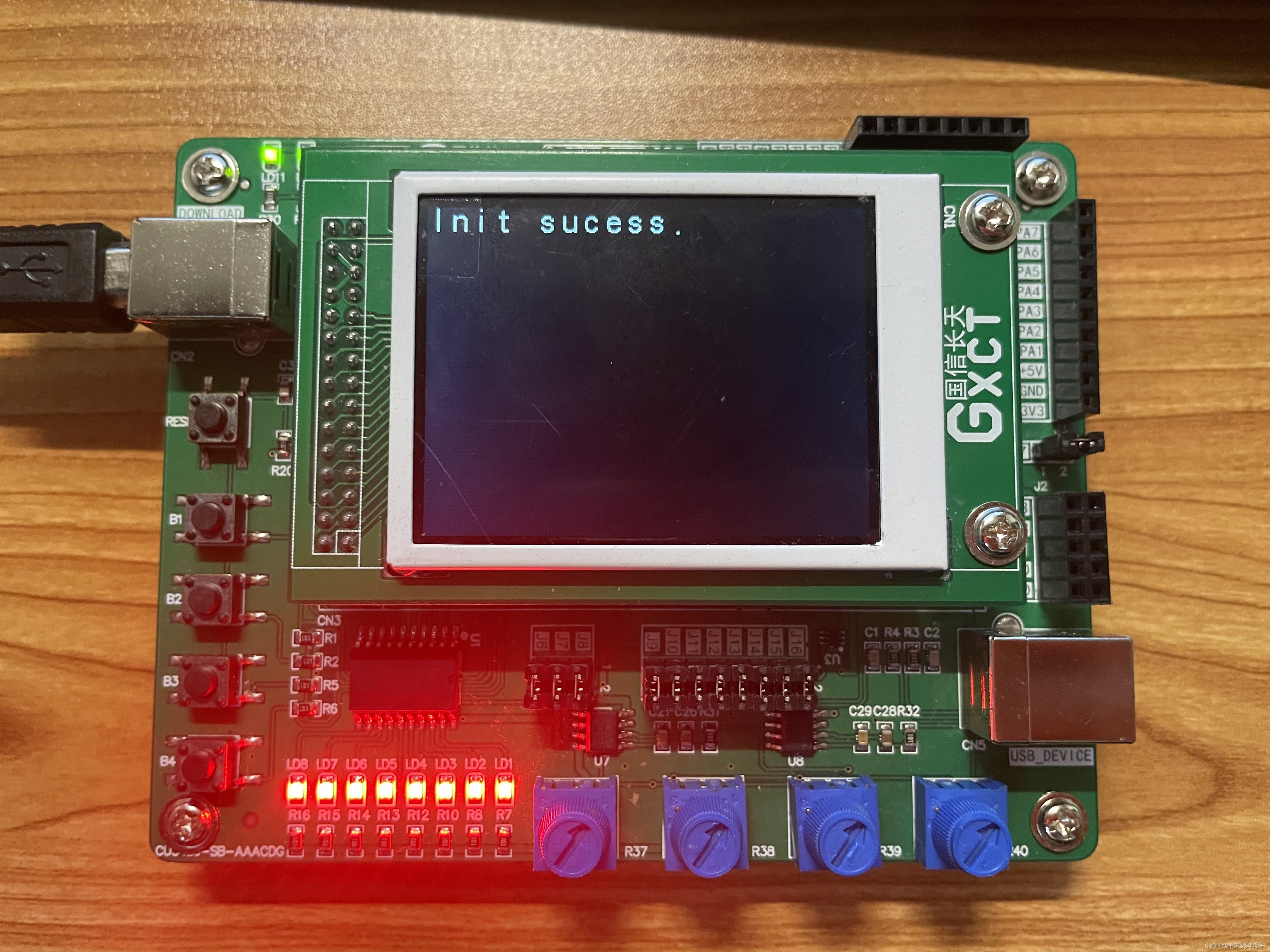
LCD_DisplayStringLine(Line0,"Init sucess."); //显示:初始化成功
HAL_Delay(1000);
LCD_Clear(Black);
//********用户初始化代码********//
while (1)
{
//********用户死循环代码********//
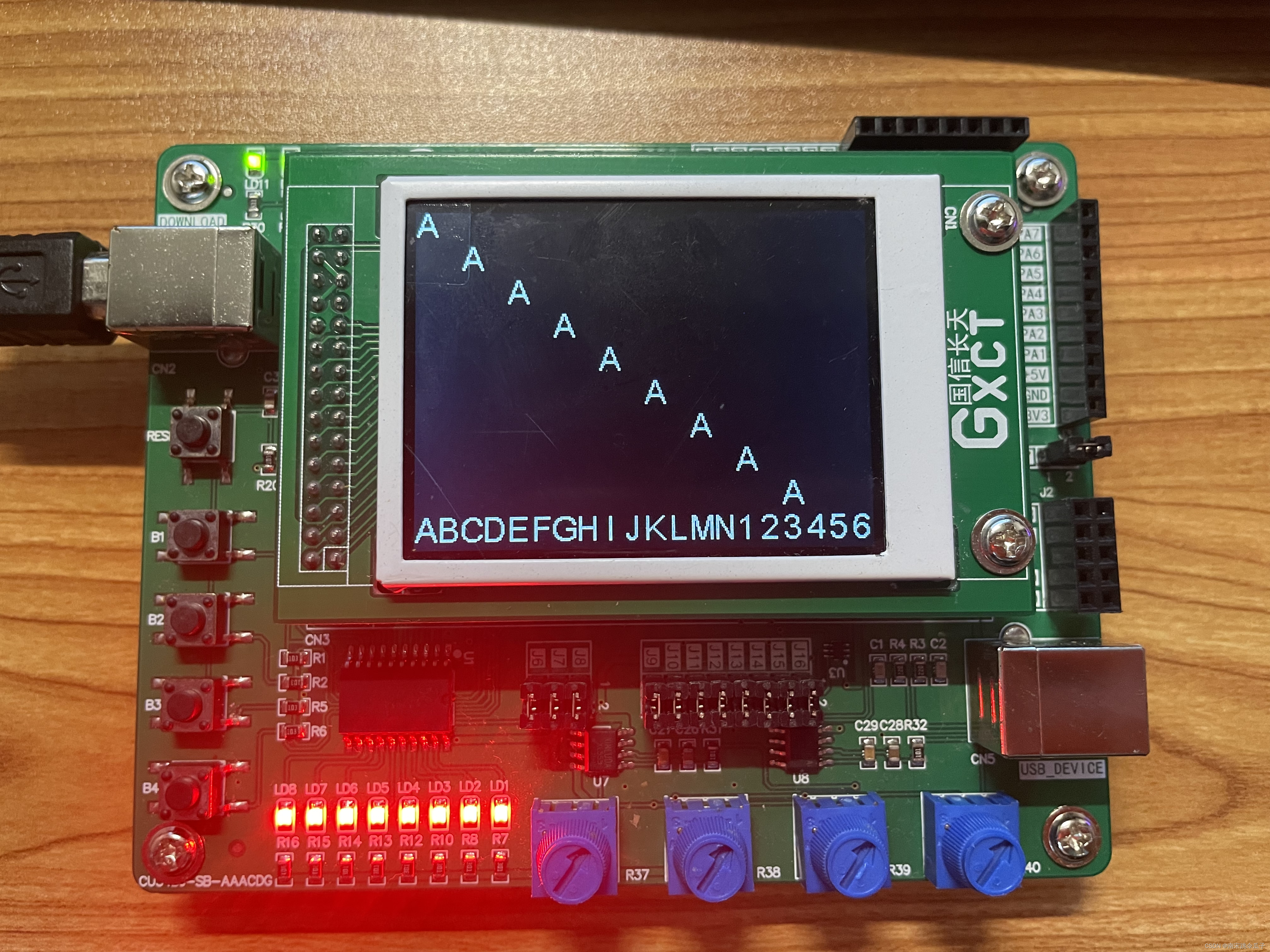
LCD_DisplayStringLine(Line0, (unsigned char *)"A");
LCD_DisplayStringLine(Line1, (unsigned char *)" A");
LCD_DisplayStringLine(Line2, (unsigned char *)" A");
LCD_DisplayStringLine(Line3, (unsigned char *)" A");
LCD_DisplayStringLine(Line4, (unsigned char *)" A");
LCD_DisplayStringLine(Line5, (unsigned char *)" A");
LCD_DisplayStringLine(Line6, (unsigned char *)" A");
LCD_DisplayStringLine(Line7, (unsigned char *)" A");
LCD_DisplayStringLine(Line8, (unsigned char *)" A");
LCD_DisplayStringLine(Line9, (unsigned char *)"ABCDEFGHIJKLMN1234567");
//********用户死循环代码********//
}
}4.编译0错误后,连接板子进行烧录。
最终效果图如下:


 被折叠的 条评论
为什么被折叠?
被折叠的 条评论
为什么被折叠?
 到【灌水乐园】发言


