


原理与接线:
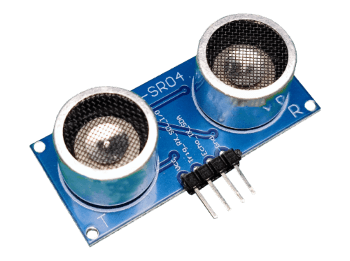
HC-SR04 超声波模块简介
HC-SR04 工作原理
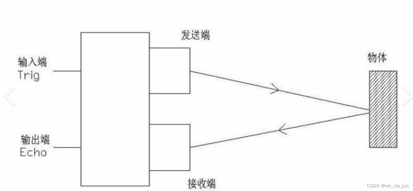
模块有2个超声波换能器(如图所示),一个发出声波,另一个接收物体反射回来的声波,这中间所经过的时间即声波传播的时间,再结合声速就能计算出:\
距离 = 声速 * 时间 ÷ 2
如何使用HC-SR04模块
模块具有4个引脚,除了电源外,有TRIG、ECHO两个引脚需要操作:
首先,向TRIG引脚发送一个高电平脉冲,来触发模块输出声波
记录ECHO引脚输出高电平的时间,即声波的飞行时间
距离 = 声速(340m/s) * 声波的飞行时间 ÷ 2

 (输入捕获的结构)
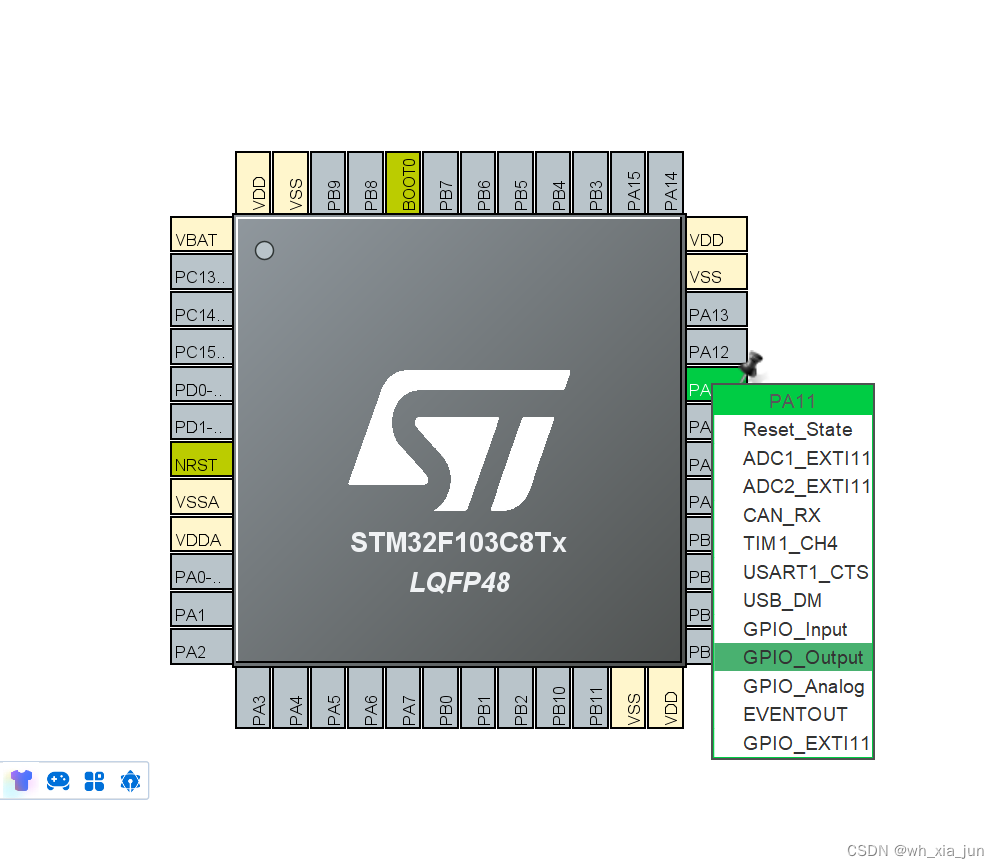
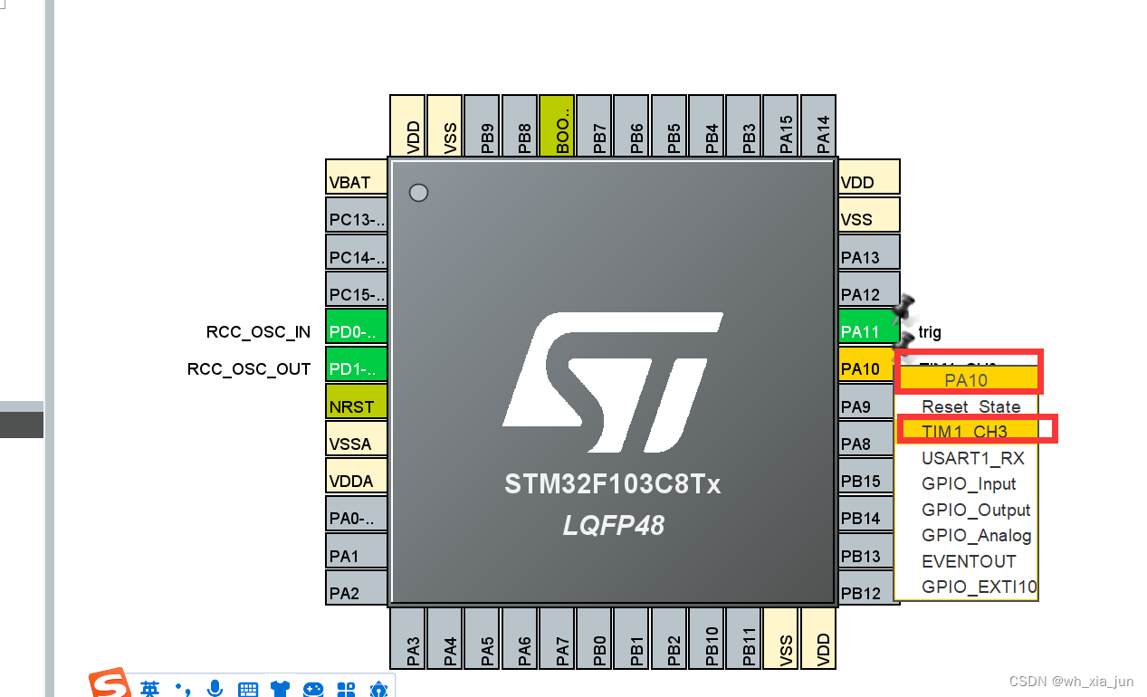
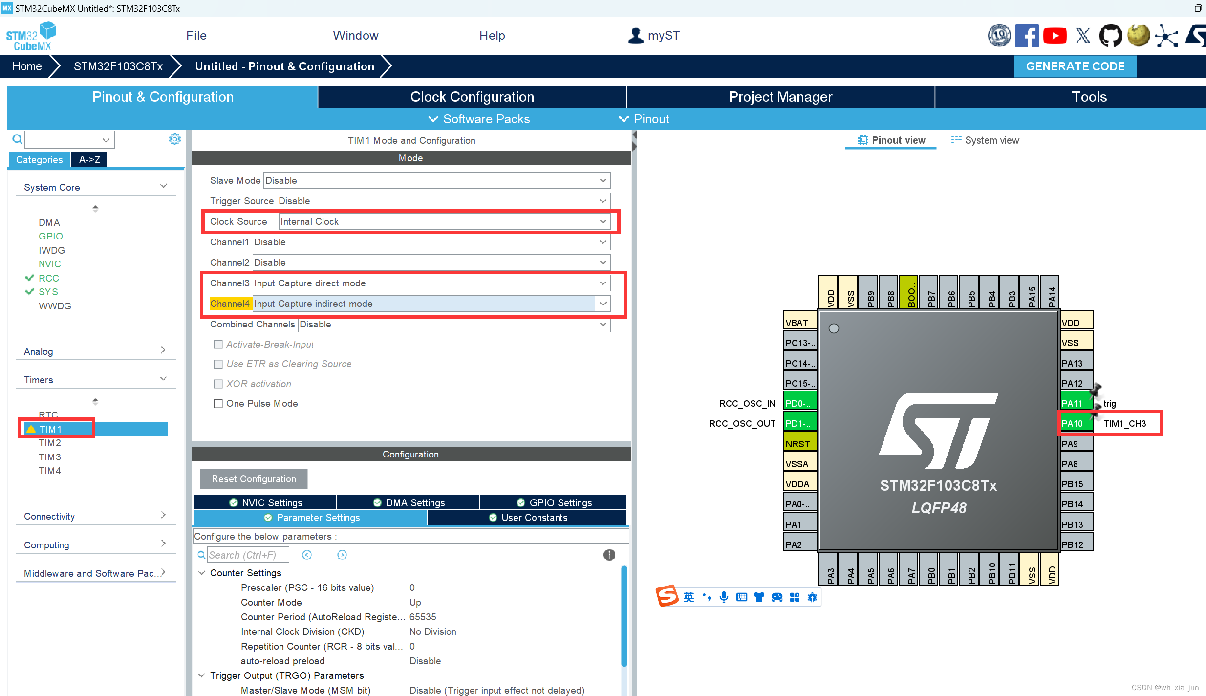
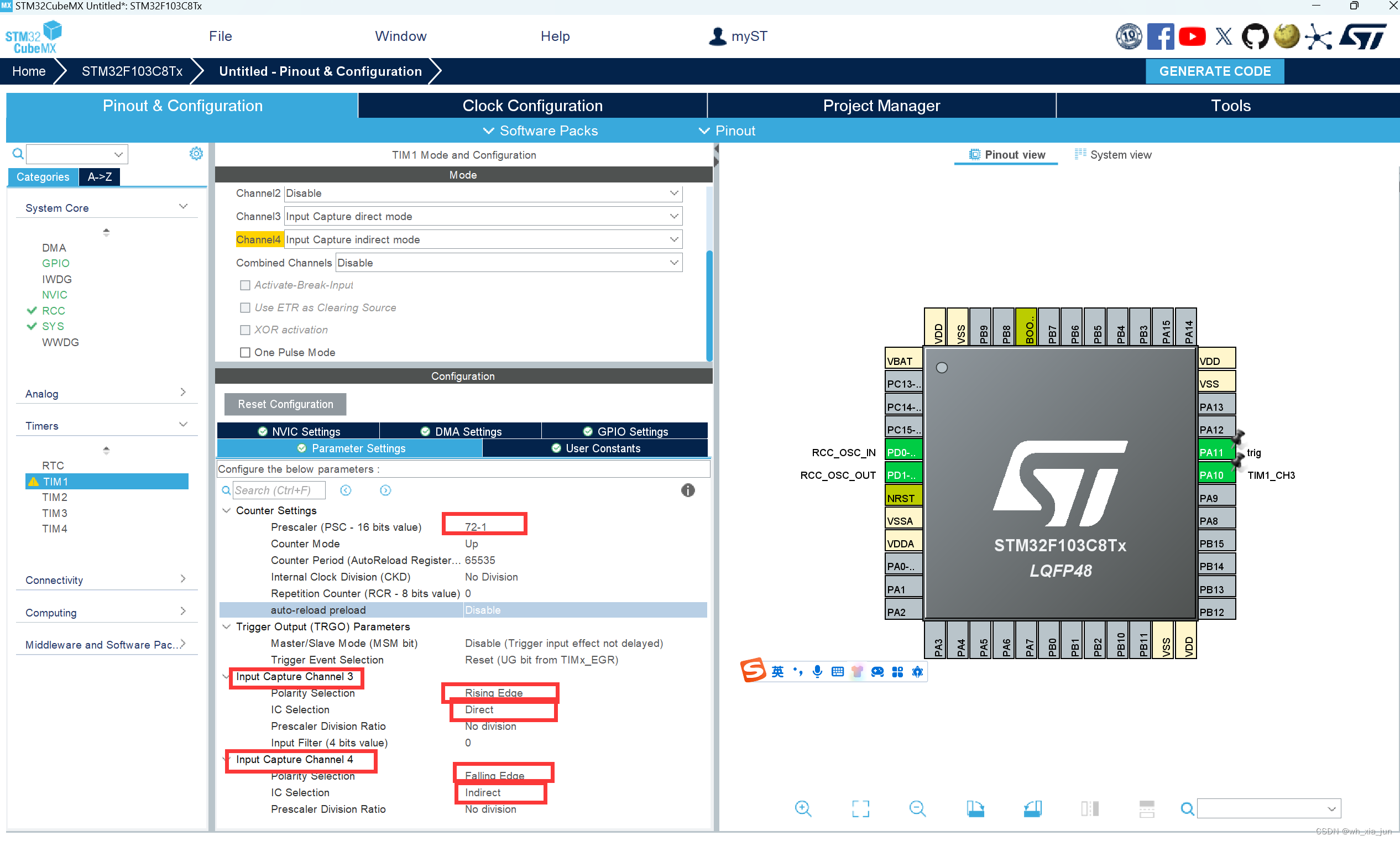
cubeMx:
PA11: 连接trig
PA10 连接echo引脚:
I2C的配置见前面的博客:
用HAL库改写江科大的stm32入门例子4-1 OLED_江科大oled移植hal库-CSDN博客
主要代码:
/* USER CODE BEGIN Header */
/**
  ******************************************************************************
  * @file           : main.c
  * @brief          : Main program body
  ******************************************************************************
  * @attention
  *
  * Copyright (c) 2024 STMicroelectronics.
  * All rights reserved.
  *
  * This software is licensed under terms that can be found in the LICENSE file
  * in the root directory of this software component.
  * If no LICENSE file comes with this software, it is provided AS-IS.
  *
  ******************************************************************************
  */
/* USER CODE END Header */
/* Includes ------------------------------------------------------------------*/
#include "main.h"
#include "i2c.h"
#include "tim.h"
#include "gpio.h"

/* Private includes ----------------------------------------------------------*/
/* USER CODE BEGIN Includes */
#include "OLED.h"
#include "stdio.h"
#include "string.h"

/* USER CODE END Includes */

/* Private typedef -----------------------------------------------------------*/
/* USER CODE BEGIN PTD */

/* USER CODE END PTD */

/* Private define ------------------------------------------------------------*/
/* USER CODE BEGIN PD */

/* USER CODE END PD */

/* Private macro -------------------------------------------------------------*/
/* USER CODE BEGIN PM */

/* USER CODE END PM */

/* Private variables ---------------------------------------------------------*/

/* USER CODE BEGIN PV */
// declare input capture value
int upEdge = 0;
int downEdge = 0;//获取下降沿时刻计数值
float distance = 0;
//declare distance


//declare voice speed
float SPEED_OF_SOUND=  0.034; //340m/s


/* USER CODE END PV */

/* Private function prototypes -----------------------------------------------*/
void SystemClock_Config(void);
/* USER CODE BEGIN PFP */

//timer input capture callback
void HAL_TIM_IC_CaptureCallback(TIM_HandleTypeDef *htim)
{
  if(htim == &htim1 && htim -> Channel == HAL_TIM_ACTIVE_CHANNEL_4)
  {
	  upEdge = HAL_TIM_ReadCapturedValue(htim, TIM_CHANNEL_3);
	  downEdge = HAL_TIM_ReadCapturedValue(htim, TIM_CHANNEL_4);
	  distance = ((downEdge - upEdge) * 0.034) / 2 ;
  }
}


/* USER CODE END PFP */

/* Private user code ---------------------------------------------------------*/
/* USER CODE BEGIN 0 */

/* USER CODE END 0 */

/**
  * @brief  The application entry point.
  * @retval int
  */
int main(void)
{

  /* USER CODE BEGIN 1 */

  /* USER CODE END 1 */

  /* MCU Configuration--------------------------------------------------------*/

  /* Reset of all peripherals, Initializes the Flash interface and the Systick. */
  HAL_Init();

  /* USER CODE BEGIN Init */

  /* USER CODE END Init */

  /* Configure the system clock */
  SystemClock_Config();

  /* USER CODE BEGIN SysInit */

  /* USER CODE END SysInit */

  /* Initialize all configured peripherals */
  MX_GPIO_Init();
  MX_TIM1_Init();
  MX_I2C1_Init();
  /* USER CODE BEGIN 2 */
		/*模块初始化*/
	OLED_Init();		//OLED初始化

 HAL_TIM_Base_Start(&htim1);//启动计时器计数

 //启用定时器对应通道的输入捕获功能
 HAL_TIM_IC_Start(&htim1,TIM_CHANNEL_3);//开启通道3的输入捕获

HAL_TIM_IC_Start_IT(&htim1,TIM_CHANNEL_4);
 char message [50] = "";

	/*OLED显示*/
	OLED_ShowChar(1, 1, 'A');				//1行1列显示字符A
  /* USER CODE END 2 */

  /* Infinite loop */
  /* USER CODE BEGIN WHILE */
  while (1)
  {
    // create pulse for trigger,pin is pa11
    HAL_GPIO_WritePin(GPIOA, GPIO_PIN_11, GPIO_PIN_SET);
    HAL_Delay(1);
    HAL_GPIO_WritePin(GPIOA, GPIO_PIN_11, GPIO_PIN_RESET);

    //clear timer1 cnt
    __HAL_TIM_SET_COUNTER(&htim1, 0);


	  sprintf(message,"距离 = %.2fcm",distance);

OLED_ShowString(2, 1, message);


    /* USER CODE END WHILE */

    /* USER CODE BEGIN 3 */
  }
  /* USER CODE END 3 */
}

/**
  * @brief System Clock Configuration
  * @retval None
  */
void SystemClock_Config(void)
{
  RCC_OscInitTypeDef RCC_OscInitStruct = {0};
  RCC_ClkInitTypeDef RCC_ClkInitStruct = {0};

  /** Initializes the RCC Oscillators according to the specified parameters
  * in the RCC_OscInitTypeDef structure.
  */
  RCC_OscInitStruct.OscillatorType = RCC_OSCILLATORTYPE_HSE;
  RCC_OscInitStruct.HSEState = RCC_HSE_ON;
  RCC_OscInitStruct.HSEPredivValue = RCC_HSE_PREDIV_DIV1;
  RCC_OscInitStruct.HSIState = RCC_HSI_ON;
  RCC_OscInitStruct.PLL.PLLState = RCC_PLL_ON;
  RCC_OscInitStruct.PLL.PLLSource = RCC_PLLSOURCE_HSE;
  RCC_OscInitStruct.PLL.PLLMUL = RCC_PLL_MUL9;
  if (HAL_RCC_OscConfig(&RCC_OscInitStruct) != HAL_OK)
  {
    Error_Handler();
  }

  /** Initializes the CPU, AHB and APB buses clocks
  */
  RCC_ClkInitStruct.ClockType = RCC_CLOCKTYPE_HCLK|RCC_CLOCKTYPE_SYSCLK
                              |RCC_CLOCKTYPE_PCLK1|RCC_CLOCKTYPE_PCLK2;
  RCC_ClkInitStruct.SYSCLKSource = RCC_SYSCLKSOURCE_PLLCLK;
  RCC_ClkInitStruct.AHBCLKDivider = RCC_SYSCLK_DIV1;
  RCC_ClkInitStruct.APB1CLKDivider = RCC_HCLK_DIV2;
  RCC_ClkInitStruct.APB2CLKDivider = RCC_HCLK_DIV1;

  if (HAL_RCC_ClockConfig(&RCC_ClkInitStruct, FLASH_LATENCY_2) != HAL_OK)
  {
    Error_Handler();
  }
}

/* USER CODE BEGIN 4 */

/* USER CODE END 4 */

/**
  * @brief  This function is executed in case of error occurrence.
  * @retval None
  */
void Error_Handler(void)
{
  /* USER CODE BEGIN Error_Handler_Debug */
  /* User can add his own implementation to report the HAL error return state */
  __disable_irq();
  while (1)
  {
  }
  /* USER CODE END Error_Handler_Debug */
}

#ifdef  USE_FULL_ASSERT
/**
  * @brief  Reports the name of the source file and the source line number
  *         where the assert_param error has occurred.
  * @param  file: pointer to the source file name
  * @param  line: assert_param error line source number
  * @retval None
  */
void assert_failed(uint8_t *file, uint32_t line)
{
  /* USER CODE BEGIN 6 */
  /* User can add his own implementation to report the file name and line number,
     ex: printf("Wrong parameters value: file %s on line %d\r\n", file, line) */
  /* USER CODE END 6 */
}
#endif /* USE_FULL_ASSERT */
本文引用、参考、copy【HAL库 STM32】输入捕获并实现超声波测距_超声波测距hal库csdn-CSDN博客
同时,感谢政闻同学,实验都是他做的,这里记录一下过程。


 被折叠的 条评论
为什么被折叠?
被折叠的 条评论
为什么被折叠?
 到【灌水乐园】发言


