小键盘TCA8418驱动调试

小键盘TCA8418驱动调试

代码中搜索发现kernel代码中有驱动

$ find -name "*tca841*"
./drivers/input/keyboard/tca8418_keypad.c
./Documentation/devicetree/bindings/input/tca8418_keypad.txt
./include/linux/input/tca8418_keypad.h

查看文档,依照说明配置dtsi

Required properties:
- compatible: "ti,tca8418"
- reg: the I2C address
- interrupts: IRQ line number, should trigger on falling edge
- linux,keymap: Keys definitions, see keypad-matrix.

配置dtsi时发现少了2个属性keypad,num-rows和keypad,num-columns

从datasheet获取芯片通讯地址

完成配置dtsi

tca8418@34 {
compatible = "ti,tca8418";
interrupt-parent = <&msm_gpio>;
interrupts = <11 0x2002>;
reg = <0x34>;
keypad,num-rows = <4>;
keypad,num-columns = <4>;
linux,keymap = <0x0000020a
0x0001000b
0x0002020b
0x0003001c
0x01000008
0x01010009
0x0102000a
0x0103000e
0x02000005
0x02010006
0x02020007
0x0203009e
0x03000002
0x03010003
0x03020004
0x0303001c>;
};

config中配置

CONFIG_KEYBOARD_TCA8418=y

编译烧写后

getevent驱动已经挂载上了,但是按按键没有反应

看原理图

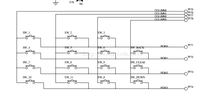
发现外围没有接上拉电阻,一般都会有个上拉电阻,之前调试过小键盘sn7326就是因为没有上拉电阻的问题
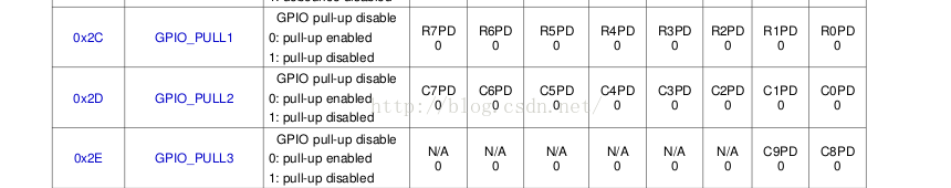
只好再研究下芯片手册

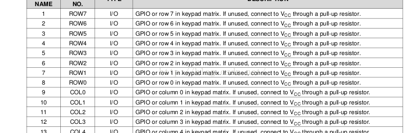
果然不用的gpio要拉个上拉,这个纠结了好久,后来看reg设置时发现, 内部默认有个上拉,通过reg可以配置上拉,默认是配置的上拉,所以也没问题

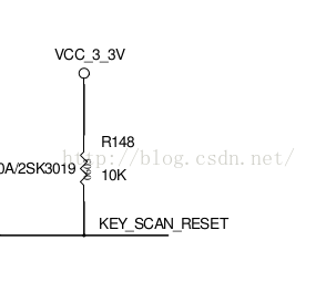
接下来看看是不是reset信号有问题,量reset信号

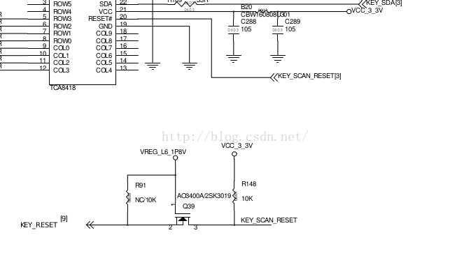
查看原理图发现reset信号方向反了,对小键盘这边reset应该是输入,上图画成了输出,不过小键盘端有个上拉,reset脚可以一直保持高电平,芯片可以一直工作,不影响

再来看看是不是中断信号有问题,看中断信号

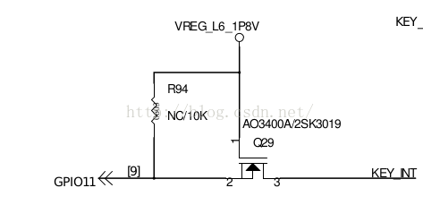
测量KEY_INT, 按键按下前为高,按下后为低,正常

测量GPIO11,按键按下前0.7V,电压不对,找到问题了

分析:从原理图上看电路应该是没问题的,GPIO11通过Q29与1.8V相接,Q29截止的话,实际上相当与拉了个很大的上拉电阻,会造成分压。Q29的1和2脚之前有个很大的电阻。

分析后把GPIO11配置修改成上拉,编译运行,小键盘开始正常工作了。但是当系统休眠后,再按按键就没有反应了。

量电压,系统休眠时1.8V掉电了,在tca8418代码中增加对VREG_L6_1P8V的控制,小键盘在系统休眠后也可以正常工作起来了。

剩下的就是收尾工作,调整下键值的对应关系。

  • 2
    点赞
  • 5
    收藏
    觉得还不错? 一键收藏
  • 14
    评论
以下是一个基于C语言的tca9555驱动代码示例: ```c #include <stdio.h> #include <stdlib.h> #include <errno.h> #include <fcntl.h> #include <string.h> #include <unistd.h> #include <linux/i2c-dev.h> #define TCA9555_I2C_ADDR 0x20 #define INPUT_PORT_REG_ADDR 0x00 #define OUTPUT_PORT_REG_ADDR 0x01 #define POLARITY_INVERSION_REG_ADDR 0x02 #define CONFIG_REG_ADDR 0x03 #define NUM_PINS 16 int i2c_fd; void tca9555_write_reg(char reg, char value) { char buf[2]; buf[0] = reg; buf[1] = value; if (write(i2c_fd, buf, 2) != 2) { perror("write"); exit(1); } } char tca9555_read_reg(char reg) { char value; if (write(i2c_fd, &reg, 1) != 1) { perror("write"); exit(1); } if (read(i2c_fd, &value, 1) != 1) { perror("read"); exit(1); } return value; } void tca9555_set_direction(int pin, int is_input) { char config_reg = tca9555_read_reg(CONFIG_REG_ADDR); if (is_input) { config_reg |= (1 << pin); } else { config_reg &= ~(1 << pin); } tca9555_write_reg(CONFIG_REG_ADDR, config_reg); } void tca9555_set_output(int pin, int value) { char output_port_reg = tca9555_read_reg(OUTPUT_PORT_REG_ADDR); if (value) { output_port_reg |= (1 << pin); } else { output_port_reg &= ~(1 << pin); } tca9555_write_reg(OUTPUT_PORT_REG_ADDR, output_port_reg); } int tca9555_get_input(int pin) { char input_port_reg = tca9555_read_reg(INPUT_PORT_REG_ADDR); return (input_port_reg >> pin) & 1; } int main() { int i; char buf[2]; char input_port_reg; i2c_fd = open("/dev/i2c-1", O_RDWR); if (i2c_fd < 0) { perror("open"); exit(1); } if (ioctl(i2c_fd, I2C_SLAVE, TCA9555_I2C_ADDR) < 0) { perror("ioctl"); exit(1); } // Set all pins to output tca9555_write_reg(CONFIG_REG_ADDR, 0x00); // Turn on every other LED for (i = 0; i < NUM_PINS; i += 2) { tca9555_set_output(i, 1); } // Read all input pins and print their values input_port_reg = tca9555_read_reg(INPUT_PORT_REG_ADDR); printf("Input values: "); for (i = 0; i < NUM_PINS; i++) { printf("%d ", (input_port_reg >> i) & 1); } printf("\n"); close(i2c_fd); return 0; } ``` 该代码连接到i2c总线,使用 ioctl() 函数将i2c设备文件的文件描述符设置为TCA9555芯片的地址。然后,使用tca9555_write_reg()和tca9555_read_reg()函数向TCA9555芯片写入和读取寄存器值,并使用tca9555_set_direction()、tca9555_set_output()和tca9555_get_input()函数来控制芯片的输出和读取输入。

“相关推荐”对你有帮助么?

  • 非常没帮助
  • 没帮助
  • 一般
  • 有帮助
  • 非常有帮助
提交
评论 14
添加红包

请填写红包祝福语或标题

红包个数最小为10个

红包金额最低5元

当前余额3.43前往充值 >
需支付:10.00
成就一亿技术人!
领取后你会自动成为博主和红包主的粉丝 规则
hope_wisdom
发出的红包
实付
使用余额支付
点击重新获取
扫码支付
钱包余额 0

抵扣说明:

1.余额是钱包充值的虚拟货币,按照1:1的比例进行支付金额的抵扣。
2.余额无法直接购买下载,可以购买VIP、付费专栏及课程。

余额充值