


COMBIN39 Element Description
COMBIN39 is a unidirectional element with nonlinear generalized force-deflection capability that can be used in any analysis. The element has longitudinal or torsional capability in 1-D, 2-D, or 3-D applications. The longitudinal option is a uniaxial tension-compression element with up to three degrees of freedom at each node: translations in the nodal x, y, and z directions. No bending or torsion is considered. The torsional option is a purely rotational element with three degrees of freedom at each node: rotations about the nodal x, y, and z axes. No bending or axial loads are considered.
The element has large displacement capability for which there can be two or three degrees of freedom at each node.
See COMBIN39 in the Mechanical APDL Theory Reference for more details about this element. The element has no mass or thermal capacitance. These may be added by using the appropriate elements (see MASS21 and MASS71). A bilinear force-deflection element with damping and gaps is also available (COMBIN40).
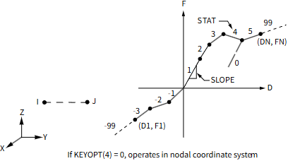
Figure 39.1: COMBIN39 Geometry
COMBIN39 Input Data
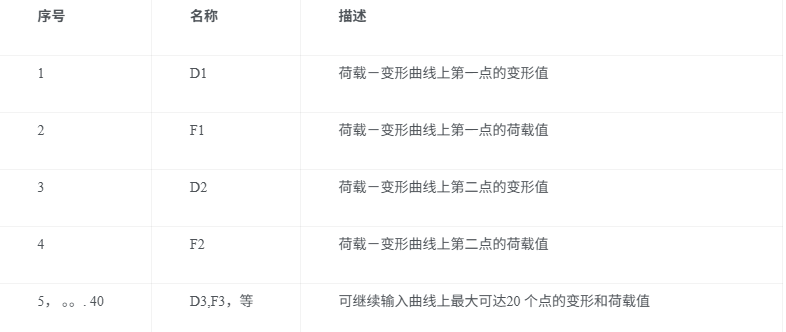
The geometry, node locations, and the coordinate system for this element are shown in Figure 39.1: COMBIN39 Geometry. The element is defined by two (preferably coincident) node points and a generalized force-deflection curve. The points on this curve (D1, F1, etc.) represent force (or moment) versus relative translation (or rotation) for structural analyses, and heat (or flow) rate versus temperature (or pressure) difference for a thermal analyses. The loads should be defined on a full 360° basis for an axisymmetric analysis.
The force-deflection curve should be input such that deflections are increasing from the third (compression) to the first (tension) quadrants. Adjacent deflections should not be nearer than 1E-7 times total input deflection range. The last input deflection must be positive. Segments tending towards vertical should be avoided. If the force-deflection curve is exceeded, the last defined slope is maintained, and the status remains equal to the last segment number. If the compressive region of the force-deflection curve is explicitly defined (and not reflected), then at least one point should also be at the origin (0,0) and one point in the first (tension) quadrant. If KEYOPT(2) = 1 (no compressive resistance), the force-deflection curve should not extend into the third quadrant. Note that this tension-only behavior can cause convergence difficulties similar to those that can be experienced by contact elements. See the Contact Technology Guide, as well as various contact element descriptions, for guidelines on overcoming convergence difficulties. Note that the number of points defining the loading curve (20 points) can be effectively doubled by using the reflective option.
Slopes of segments may be either positive or negative, except that the slopes at the origin must be positive and, if KEYOPT(1) = 1, slopes at the ends may not be negative. Also, if KEYOPT(1) = 1, force-deflection points may not be defined in the second or fourth quadrants and the slope of any segment may not be greater than the slope of the segment at the origin in that quadrant.
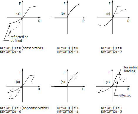
The KEYOPT(1) option allows either unloading along the same loading curve or unloading along the line parallel to the slope at the origin of the curve. This second option allows modeling of hysteretic effects. As illustrated in Figure 39.2: COMBIN39 Force-Deflection Curves, the KEYOPT(2) option provides several loading curve capabilities.
The KEYOPT(3) option selects one degree of freedom. This may be a translation, a rotation, a pressure or a temperature.
Alternately, the element may have more than one type of degree of freedom (KEYOPT(4) > 0). The two nodes defining the element should not be coincident, since the load direction is colinear with the line joining the nodes. The longitudinal option (KEYOPT(4) = 1 or 3) creates a uniaxial tension-compression element with two or three translational degrees of freedom at each node. No bending or torsion is considered. The torsional option (KEYOPT(4) = 2) creates a purely rotational element with three rotational degrees of freedom at each node. No bending or axial loads are considered. The stress stiffening capability is applicable when forces are applied, but not when torsional loads are applied.
The element has large displacement capability with two or three degrees of freedom for each node when you use KEYOPT(4) = 1 or 3 in combination with NLGEOM,ON.
Convergence difficulties caused by moving through rapid changes of the slope (tangent) of the force-deflection diagram are sometimes helped by use of line search (LNSRCH,ON).
A summary of the element input is given in "COMBIN39 Input Summary". A general description of element input is given in Element Input.
COMBIN39 Input Summary
Nodes
I, J
Degrees of Freedom
| UX, UY, UZ, ROTX, ROTY, ROTZ, PRES, or TEMP. |
| Make 1-D choices with KEYOPT(3). |
| Make limited 2- or 3-D choices with KEYOPT(4). |
Real Constants
| D1, F1, D2, F2, D3, F3, |
| D4, F4, ..., D20, F20 |
| See Table 39.1: COMBIN39 Real Constants for a description of the real constants |
Material Properties
MP command: BETD, DMPR
Surface Loads
None
Body Loads
None
Special Features
| Large displacement |
| Linear perturbation |
| Nonlinearity |
| Stress stiffening |
KEYOPT(1)
Unloading path:
0 --
Unload along same loading curve
1 --
Unload along line parallel to slope at origin of loading curve
KEYOPT(2)
Element behavior under compressive load:
0 --
Compressive loading follows defined compressive curve (or reflected tensile curve if not defined)
1 --
Element offers no resistance to compressive loading
2 --
Loading initially follows tensile curve then follows compressive curve after buckling (zero or negative stiffness)
KEYOPT(3)
Element degrees of freedom (1-D) (KEYOPT(4) overrides KEYOPT(3)):
0, 1 --
UX (Displacement along nodal X axes)
2 --
UY (Displacement along nodal Y axes)
3 --
UZ (Displacement along nodal Z axes)
4 --
ROTX (Rotation about nodal X axes)
5 --
ROTY (Rotation about nodal Y axes)
6 --
ROTZ (Rotation about nodal Z axes)
7 --
PRES
8 --
TEMP
KEYOPT(4)
Element degrees of freedom (2-D or 3-D):
0 --
Use any KEYOPT(3) option
1 --
3-D longitudinal element (UX, UY and UZ)
2 --
2-D torsional element (ROTX, ROTY and ROTZ)
KEYOPT(6)
Element output:
0 --
Basic element printout
1 --
Also print force-deflection table for each element (only at first iteration of problem)
KEYOPT(7)
Element level time increment control:
0 --
No control
1 --
Predictions are made to achieve a reasonable time (or load) increment
Table 39.1: COMBIN39 Real Constants

COMBIN39 Output Data
The solution output associated with the element is in two forms:
-
Nodal degree of freedom results included in the overall nodal solution
-
Additional element output as shown in Table 39.2: COMBIN39 Element Output Definitions
The nodal displacements and forces correspond to the degrees of freedom selected with KEYOPT(3). For an axisymmetric analysis, the element forces are expressed on a full 360° basis. The element value STRETCH is the relative deflection at the end of the substep (e.g., UX(J) - UX(I) - UORIG, etc.). STAT and OLDST describe the curve segment number at the end of the current and previous substeps, respectively. STAT or OLDST = 0 indicates nonconservative unloading (KEYOPT(1) = 1). A status of 99 or -99 (as shown in Figure 39.1: COMBIN39 Geometry) indicates that the active load point on the curve is outside of the supplied data. The slope of the last segment that is provided is simply continued beyond the last data point.
A general description of solution output is given in Solution Output. See the Basic Analysis Guide for ways to view results.
Figure 39.2: COMBIN39 Force-Deflection Curves
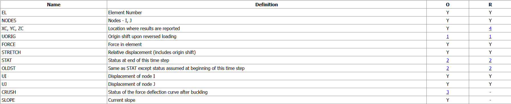
The Element Output Definitions table uses the following notation:
A colon (:) in the Name column indicates that the item can be accessed by the Component Name method (ETABLE, ESOL). The O column indicates the availability of the items in the file Jobname.OUT. The R column indicates the availability of the items in the results file.
In either the O or R columns, “Y” indicates that the item is always available, a number refers to a table footnote that describes when the item is conditionally available, and “-” indicates that the item is not available.
Table 39.2: COMBIN39 Element Output Definitions
-
If KEYOPT(1) = 1
-
0 - Indicates nonconservative unloading
1-20 - Curve segment number at end of time step
99 - Beyond last segment (last segment is extrapolated) (negative STAT values indicate compressive segments)
-
If KEYOPT(2) = 2 and if the value of CRUSH is:
0 - Use defined tensile curve
1 - Use reflected compressive curve in tension (element has been compressed)
-
Available only at centroid as a *GET item.
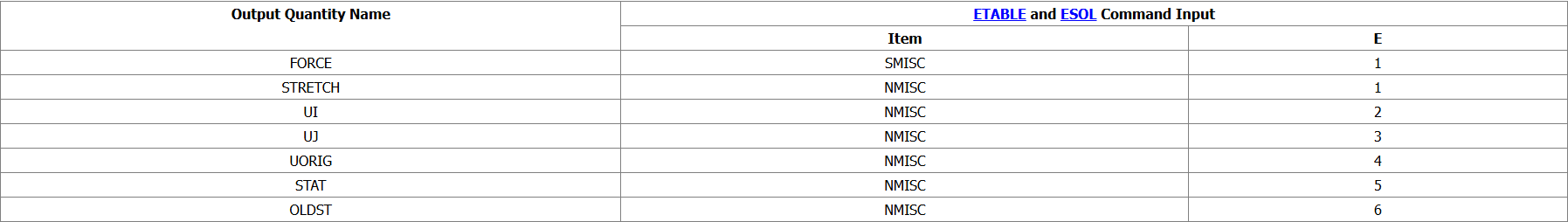
Table 39.3: COMBIN39 Item and Sequence Numbers lists output available through the ETABLE command using the Sequence Number method. See The General Postprocessor (POST1) in the Basic Analysis Guide and The Item and Sequence Number Table in this reference for more information. The following notation is used in Table 39.3: COMBIN39 Item and Sequence Numbers:
Name
output quantity as defined in the Table 39.2: COMBIN39 Element Output Definitions
Item
predetermined Item label for ETABLE command
E
sequence number for single-valued or constant element data
Table 39.3: COMBIN39 Item and Sequence Numbers
COMBIN39 Assumptions and Restrictions
-
If you specify KEYOPT(4) = 0, the element has only one degree of freedom per node. This degree of freedom defined by KEYOPT(3), is specified in the nodal coordinate system and is the same for both nodes (see Elements That Operate in the Nodal Coordinate System). KEYOPT(3) also defines the direction of the force. Nodes I and J may be anywhere in space (preferably coincident).
-
If you specify KEYOPT(4) ≠ 0, the element has two or three displacement degrees of freedom per node. Nodes I and J should not be coincident, since the line joining the nodes defines the direction of the force.
-
The element is defined such that a positive displacement of node J relative to node I tends to put the element in tension.
-
The element is nonlinear and requires an iterative solution.
-
The nonlinear behavior of the element operates only in static and nonlinear transient dynamic analyses.
-
As with most nonlinear elements, loading and unloading should occur gradually.
-
When the element is also nonconservative, loads should be applied along the actual load history path and in the proper sequence.
-
The element can not be deactivated with the EKILL command.
-
The real constants for this element can not be changed from their initial values.
-
Whenever the force that the element carries changes sign, UORIG is reset, and the origin of the force-deflection curve effectively shifts over to the point where the force changed sign. If KEYOPT(2) = 1 and the force tends to become negative, the element "breaks" and no force is transmitted until the force tends to become positive again.
-
When KEYOPT(1) = 1, the element is both nonlinear and nonconservative.
-
In a thermal analysis, the temperature or pressure degree of freedom acts in a manner analogous to the displacement.
COMBIN39 Product Restrictions
When used in the product(s) listed below, the stated product-specific restrictions apply to this element in addition to the general assumptions and restrictions given in the previous section.
ANSYS Mechanical Premium
-
The PRES DOF (KEYOPT(3) = 7) is not available.
COMBIN39 单元类型描述
COMBIN39 是一个具有非线性功能的单向单元,可对此单元输入广义的力-变形曲线.该单元可用于任何分析之中.在一维、二维和三维的应用中,本单元都有轴向或扭转功能.轴向选项(longitudinal) 代表轴向拉压单元,每个节点具有3 个自由度:沿节点坐标系X,Y,Z 的平动,不考虑弯曲和扭转。扭转选项(torsional) 代表纯扭单元,每个节点具有3 个自由度:绕节点坐标轴X,Y, Z 的转动,不考虑弯曲和轴向荷载。
此单元仅当每个节点有两个或者三个自由度的时候,才可以具有大位移的功能。
单元的详细特性请参考理论手册中的COMBIN39 单元。本单元没有质量和热容量,这些性能可以利用其他适当的单元(如MASS21 和MASS71) 来加入。ANSYS 还提供了具有阻尼和间隙的双线性力-变形单元(COMBIN40)
下面是本单元示意图。
输入数据
单元的几何形状、节点位置和坐标系如图39—1(COMBIN39 单元示意图)所示。此单元可由二个节点和一条广义荷载-变形曲线定义。在结构分析中,曲线上的各点(D1,F1 等等)代表力-平动位移关系或者弯矩-转动位移关系;而在热分析中,这些点则表示热率-温度关系或者热流率-压力关系。进行轴对称分析时,应在整个360°范围内定义荷载。
输入的荷载-变形曲线应当是从第三象限(压区)递增至第一象限(拉区)。两个相邻点之间的变形差值与输入的总变形的比值不应小至1E-7 左右。输入的最后一个变形必须为正值.要避免出现近乎竖直的线段。超出所定义的荷载-变形曲线范围后,荷载-变形关系维持为超出前的最后一段曲线表达的关系,此时状态标志亦等于最后一段的段号。如果压区的曲线有显式的定义(即不是通过拉区的镜像所得), 那么在(0,0) 处和第一象限(拉区)内都必须至少定义一个点。若设置了关键字KEYOPT(2)=1(不能承受压力),则荷载-变形曲线不得延伸到第三象限内.值得注意的是,与接触单元相似,这种纯受拉的性能可能会导致计算时的收敛困难.可以参考“ANSYS 结构分析指南”中的接触部分以及本手册中对接触单元的描述,其中可以找到克服这种收敛困难的指要。特别提示:使用“镜像”这一选项可使得用于定义曲线的点数(原有20 个)实现翻番的效果。
每段线的斜率可正可负,但是通过原点的那一段除外:它的斜率必须为正。在设置关键字KEYOPT(1)=1 的情况下,最末端的那段线斜率不可为负。同时,在第二和第四象限内不能定义荷载-变形点,且其他各段线的斜率不得大于通过原点的那一段。
关键字KEYOPT(1)是卸载方式选项,可以选择沿与加载相同的路径卸载,亦可按平行于原点处的线段的斜率卸载。后一种方式可用于模拟滞回效应。关键字KEYOPT(2)提供了几种性能不同的加载曲线,如图39-2(COMBIN39单元荷载-变形曲线)所示。
当节点仅有一个自由度时,通过关键字KEYOPT(3)可选定自由度的类型:可以是一个方向的平动自由度、一个方向的转动自由度、一种压力或者一个温度。
另外,此单元的节点亦可具有多种类型的自由度(通过设置关键字KEYOPT(4)>0).此时单元的两个节点位置不可重合,因为加载的方向与两节点的连线方向间存在线性关系。选择轴向选项(KEYOPT(4)=1 或3)将会创建轴向拉压单元,其每个节点具有两个或三个平动自由度。不考虑弯曲和扭转。选择扭转选项(KEYOPT(4)=2)则可创建纯扭单元,此时单元的每个节点仅具有三个转动自由度。不考虑弯曲和轴向荷载。施加荷载时,应力刚化功能可用,但是有扭转荷载时该功能不可用。
当同时设置关键字KEYOPT(4)=1 或3 并使用命令NLGEOM,ON 时,此单元具有大位移的功能,且其每个节点仅有两个或者三个自由度.
对于在加(卸)载通过荷载-变形曲线的斜率(切线斜率)变化过快的点时所产生的收敛困难,使用直线搜索法(LNSRCH,ON)常常会有所帮助。
“COMBIN39 单元输入一览”给出了此单元输入的总结。“单元一般特性”中的“单元输入”项则给出了所有单元输入的通用性描述。
单元输入
节点
I, J
节点自由度
| UX, UY, UZ, ROTX, ROTY, ROTZ, PRES, or TEMP. |
| 可通过KEYOPT(3) 选择设为一维单元 |
| 可通过KEYOPT(4) 选择设为有限的二维或三维单元 |
Real Constants
| D1, F1, D2, F2, D3, F3, |
| D4, F4, ..., D20, F20 |
| See Table 39.1: COMBIN39 Real Constants for a description of the real constants |
实常数
MP command: BETD, DMPR
表面荷载
不支持
体荷载
不支持
特殊用法
| Large displacement 大位移 |
| Linear perturbation 线性 |
| Nonlinearity 非线性 |
| Stress stiffening 应力刚化 |
KEYOPT(1)
控制卸载路径
0 --
沿与加载相同的路径卸载
1 --
按平行于原点处的线段的斜率卸载
KEYOPT(2)
控制单元受压时的性能
0 --
按照所定义的受压曲线(无定义时则使用受拉部分的镜像)加压力荷载
1 --
单元不能承受压力荷载
2 --
初始加载时按照受拉曲线,屈曲后(出现零刚度或负刚度)才按照受压曲线加载
KEYOPT(3)
控制一维单元时自由度的类型(设置有KEYOPT(4)时,它将覆盖KEYOPT(3))
0, 1 --
UX(沿X 轴方向平动)
2 --
UY(沿Y 轴方向平动)
3 --
UZ(沿Z 轴方向平动)
4 --
ROTX(绕X 轴转动)
5 --
ROTX(绕Y 轴转动)
6 --
ROTX(绕Z 轴转动)
7 --
PRES(压力)
8 --
TEMP(温度)
KEYOPT(4)
控制二维单元或者三维单元时自由度的类型
0 --
三维轴向单元(UX,UY 和UZ)
1 --
三维纯扭单元(ROTX,ROTY 和ROTZ)
2 --
二维轴向单元.(UX,UY)此时单元必须位于X-Y 平面内。
KEYOPT(6)
控制单元输出
0 --
基本单元输出
1 --
打印出荷载-位移曲线(仅在某问题进行第一次迭代时)
实常数
COMBIN39 输出数据
此单元可输出的解包含以下两个方面:
-
总体节点解中该单元组成节点对应自由度的结果
-
附加单元输出可参见表39-2(COMBIN39 单元输出信息表)
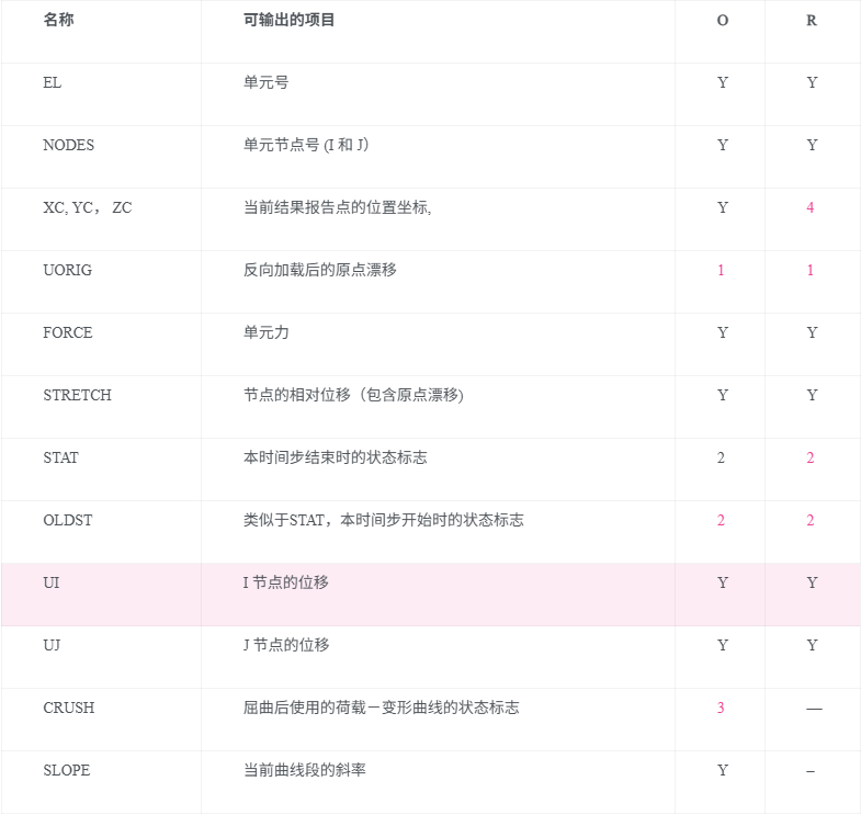
节点的位移和力对应于通过 KEYOPT(3) 选择的自由度。对于轴对称分析,元素的力以完整的 360° 基准来表示。元素值 STRETCH 是子步结束时的相对位移(例如,UX(J) - UX(I) - UORIG 等)。STAT 和 OLDST 分别描述当前和先前子步结束时的曲线段编号。STAT 或 OLDST = 0 表示非保守卸载(即 KEYOPT(1) = 1)。状态为 99 或 -99(如图 39.1: COMBIN39 几何图所示)表示曲线上的活动加载点超出了提供的数据范围。最后提供的段的斜率会直接延续到最后一个数据点之后。
关于解算输出的详细描述,请参见 Solution Output。有关如何查看结果的更多信息,请参见 Basic Analysis Guide。
元素输出定义表使用以下符号:
在 Name 列中的冒号(:)表示该项可以通过 Component Name 方法访问(例如,ETABLE,ESOL)。O 列表示该项在文件 Jobname.OUT 中的可用性。R 列表示该项在结果文件中的可用性。
在 O 或 R 列中,"Y" 表示该项始终可用,数字表示一个表格脚注,描述该项在特定条件下可用,"-" 表示该项不可用。
Table 39.2: COMBIN39 单元输出信息表
- 若KEYOPT(1)=1
-
0 - 表示非保守性卸载
1-20 - 最后一时间步所处曲线段的段号
99 - 已超出了最后一段曲线(按最后一段外插取值)(负的STAT 表明在压区)
-
0 - 表示受拉时使用原定义的拉伸曲线
1 - 表示受拉时使用原定义压区曲线在拉区的镜像(此单元之前曾经受压)
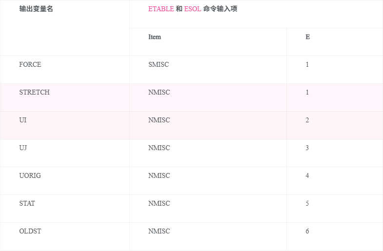
“COMBIN39 项目和序号表”中列出了在后处理中可通过ETABLE 命令加参数及数字序号的方法定义可列表察看的有关变量的细则。详见《ANSYS 基本分析指南》中有关“通用后处理 (POST1)”和“项目和序号表”部分.下面是表格的一些使用说明:
Name
指在“LINK1 单元输出数据说明表”中的有关变量.
Item
命令ETABLE 中使用的参数。
E
单元数据为常数或单值时对应的序号。
Table 39.3: COMBIN39 单元项目和序号表
COMBIN39 假设和限制
-
如果你指定 KEYOPT(4) = 0,则该元素在每个节点只有一个自由度。这个自由度由 KEYOPT(3) 定义,且它是通过节点坐标系统来指定的,并且两个节点的自由度是相同的(请参见 Elements That Operate in the Nodal Coordinate System)。KEYOPT(3) 还定义了力的方向。节点 I 和 J 可以位于空间中的任何位置(最好重合)
-
如果你指定 KEYOPT(4) ≠ 0,则该元素在每个节点有两个或三个位移自由度。节点 I 和 J 不应重合,因为连接节点的线定义了力的方向。
-
该元素的定义方式是,当节点 J 相对于节点 I 发生正位移时,元素趋向于处于拉伸状态。
-
该元素是非线性的,因此需要迭代求解。
-
该元素的非线性行为仅在静态分析和非线性瞬态动态分析中起作用。
-
与大多数非线性元素一样,加载和卸载应逐渐进行。
-
当该元素也表现为非保守性时,加载应沿实际的加载历史路径进行,并且按正确的顺序施加。
-
该元素不能通过 EKILL 命令进行停用。
-
该元素的实常数无法从其初始值进行更改。
-
每当该元素承载的力发生符号变化时,UORIG 会被重置,力-位移曲线的原点实际上会移动到力符号变化的位置。如果 KEYOPT(2) = 1 且力趋向于变为负值,则该元素会“断裂”,在力变为正值之前,不会传递任何力。
-
当 KEYOPT(1) = 1 时,该元素既是非线性的,又是非保守的。
-
在热分析中,温度或压力自由度的作用方式类似于位移自由度。


 1万+
1万+

 被折叠的 条评论
为什么被折叠?
被折叠的 条评论
为什么被折叠?
 到【灌水乐园】发言


